2001 CHRYSLER VOYAGER headlamp
[x] Cancel search: headlampPage 1096 of 4284
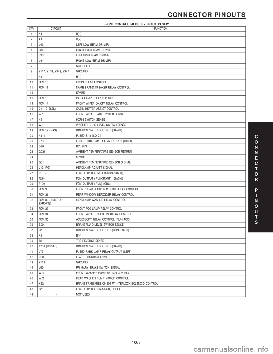
FRONT CONTROL MODULE - BLACK 49 WAYCAV CIRCUIT FUNCTION
1 A1 B(+)
2 A1 B(+)
3 L43 LEFT LOW BEAM DRIVER
4 L34 RIGHT HIGH BEAM DRIVER
5 L33 LEFT HIGH BEAM DRIVER
6 L44 RIGHT LOW BEAM DRIVER
7 - NOT USED
8 Z117, Z118, Z343, Z344 GROUND
9 A1 B(+)
10 FCM 10 HORN RELAY CONTROL
11 FCM 11 NAME BRAND SPEAKER RELAY CONTROL
12 - SPARE
13 FCM 13 PARK LAMP RELAY CONTROL
14 FCM 14 FRONT WIPER ON/OFF RELAY CONTROL
15 C41 (DIESEL) CABIN HEATER ASSIST CONTROL
16 W7 FRONT WIPER PARK SWITCH SENSE
17 X3 HORN SWITCH SENSE
18 W1 WASHER FLUID LEVEL SWITCH SENSE
19 FCM 19 (GAS) IGNITION SWITCH OUTPUT (START)
20 A114 FUSED B(+) (I.O.D.)
21 L78 FUSED PARK LAMP RELAY OUTPUT (RIGHT)
22 D25 PCI BUS
23 G931 AMBIENT TEMPERATURE SENSOR RETURN
24 - SPARE
25 G31 AMBIENT TEMPERATURE SENSOR SIGNAL
26 L13 (RG) HEADLAMP ADJUST SIGNAL
27 F1, F2 FCM OUTPUT (UNLOCK-RUN-START)
28 F214 FCM OUTPUT (RUN-START) (SIACM)
29 F100 FCM OUTPUT (RUN) (ORC)
30 FCM 30 FRONT/REAR BLOWER MOTOR RELAY CONTROL
31 FCM 31 REAR WINDOW DEFOGGER RELAY CONTROL
32 FCM 32 (BUILT-UP-
EXPORT))HEADLAMP WASHER RELAY CONTROL
33 FCM 33 FRONT FOG LAMP RELAY CONTROL
34 FCM 34 FRONT WIPER HIGH/LOW RELAY CONTROL
35 FCM 35 ACCESSORY RELAY CONTROL (RUN-ACC)
36 B20 BRAKE FLUID LEVEL SWITCH SENSE
37 F20 IGNITION SWITCH OUTPUT (RUN-START)
38 A1 B(+)
39 T2 TRS REVERSE SENSE
40 T753 (DIESEL) IGNITION SWITCH OUTPUT (START)
41 L77 FUSED PARK LAMP RELAY OUTPUT (LEFT)
42 D23 FLASH PROGRAM ENABLE
43 Z116 GROUND
44 L50 PRIMARY BRAKE SWITCH SIGNAL
45 W10 FRONT WASHER PUMP MOTOR CONTROL
46 W20 REAR WASHER PUMP MOTOR CONTROL
47 K32 BRAKE TRANSMISSION SHIFT INTERLOCK SOLENOID CONTROL
48 F201 FCM OUTPUT (RUN-START) (ORC)
49 - NOT USED
C
O
N
N
E
C
T
O
R
P
I
N
O
U
T
S
1067
CONNECTOR PINOUTS
Page 1097 of 4284
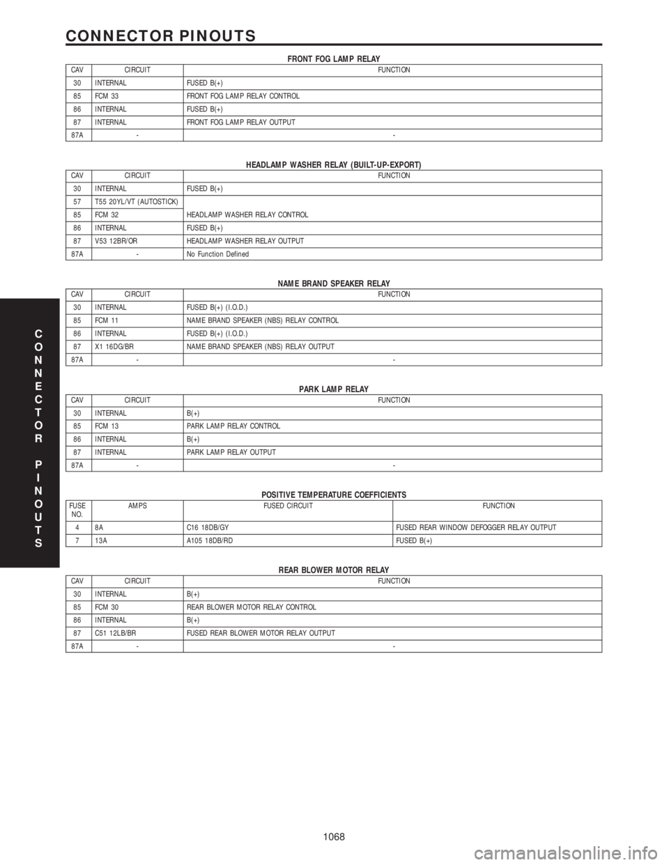
FRONT FOG LAMP RELAYCAV CIRCUIT FUNCTION
30 INTERNAL FUSED B(+)
85 FCM 33 FRONT FOG LAMP RELAY CONTROL
86 INTERNAL FUSED B(+)
87 INTERNAL FRONT FOG LAMP RELAY OUTPUT
87A --
HEADLAMP WASHER RELAY (BUILT-UP-EXPORT)CAV CIRCUIT FUNCTION
30 INTERNAL FUSED B(+)
57 T55 20YL/VT (AUTOSTICK)
85 FCM 32 HEADLAMP WASHER RELAY CONTROL
86 INTERNAL FUSED B(+)
87 V53 12BR/OR HEADLAMP WASHER RELAY OUTPUT
87A - No Function Defined
NAME BRAND SPEAKER RELAYCAV CIRCUIT FUNCTION
30 INTERNAL FUSED B(+) (I.O.D.)
85 FCM 11 NAME BRAND SPEAKER (NBS) RELAY CONTROL
86 INTERNAL FUSED B(+) (I.O.D.)
87 X1 16DG/BR NAME BRAND SPEAKER (NBS) RELAY OUTPUT
87A --
PARK LAMP RELAYCAV CIRCUIT FUNCTION
30 INTERNAL B(+)
85 FCM 13 PARK LAMP RELAY CONTROL
86 INTERNAL B(+)
87 INTERNAL PARK LAMP RELAY OUTPUT
87A --
POSITIVE TEMPERATURE COEFFICIENTSFUSE
NO.AMPS FUSED CIRCUIT FUNCTION
4 8A C16 18DB/GY FUSED REAR WINDOW DEFOGGER RELAY OUTPUT
7 13A A105 18DB/RD FUSED B(+)
REAR BLOWER MOTOR RELAYCAV CIRCUIT FUNCTION
30 INTERNAL B(+)
85 FCM 30 REAR BLOWER MOTOR RELAY CONTROL
86 INTERNAL B(+)
87 C51 12LB/BR FUSED REAR BLOWER MOTOR RELAY OUTPUT
87A --
C
O
N
N
E
C
T
O
R
P
I
N
O
U
T
S
1068
CONNECTOR PINOUTS
Page 1108 of 4284
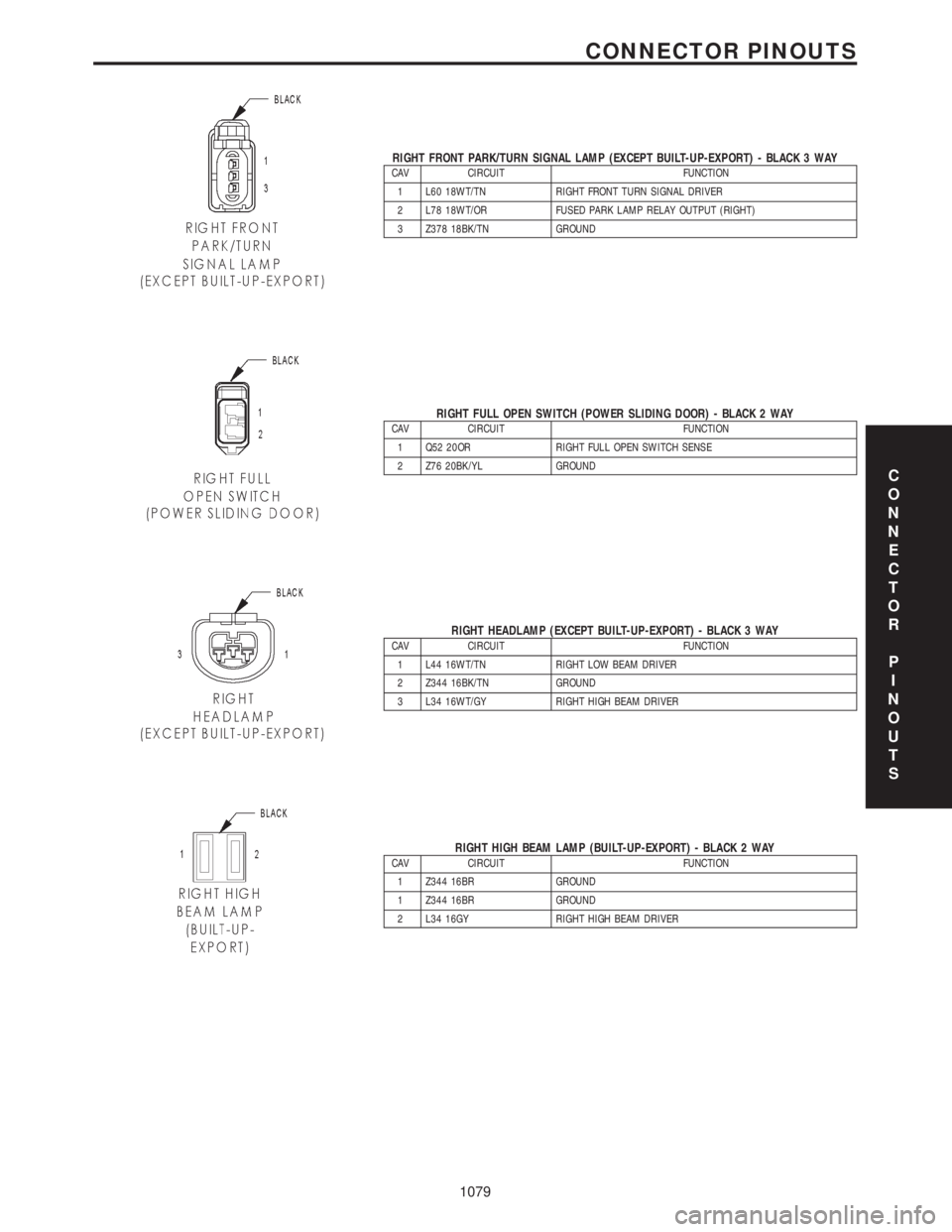
RIGHT FRONT PARK/TURN SIGNAL LAMP (EXCEPT BUILT-UP-EXPORT) - BLACK 3 WAYCAV CIRCUIT FUNCTION
1 L60 18WT/TN RIGHT FRONT TURN SIGNAL DRIVER
2 L78 18WT/OR FUSED PARK LAMP RELAY OUTPUT (RIGHT)
3 Z378 18BK/TN GROUND
RIGHT FULL OPEN SWITCH (POWER SLIDING DOOR) - BLACK 2 WAYCAV CIRCUIT FUNCTION
1 Q52 20OR RIGHT FULL OPEN SWITCH SENSE
2 Z76 20BK/YL GROUND
RIGHT HEADLAMP (EXCEPT BUILT-UP-EXPORT) - BLACK 3 WAYCAV CIRCUIT FUNCTION
1 L44 16WT/TN RIGHT LOW BEAM DRIVER
2 Z344 16BK/TN GROUND
3 L34 16WT/GY RIGHT HIGH BEAM DRIVER
RIGHT HIGH BEAM LAMP (BUILT-UP-EXPORT) - BLACK 2 WAYCAV CIRCUIT FUNCTION
1 Z344 16BR GROUND
1 Z344 16BR GROUND
2 L34 16GY RIGHT HIGH BEAM DRIVER
C
O
N
N
E
C
T
O
R
P
I
N
O
U
T
S
1079
CONNECTOR PINOUTS
Page 1220 of 4284
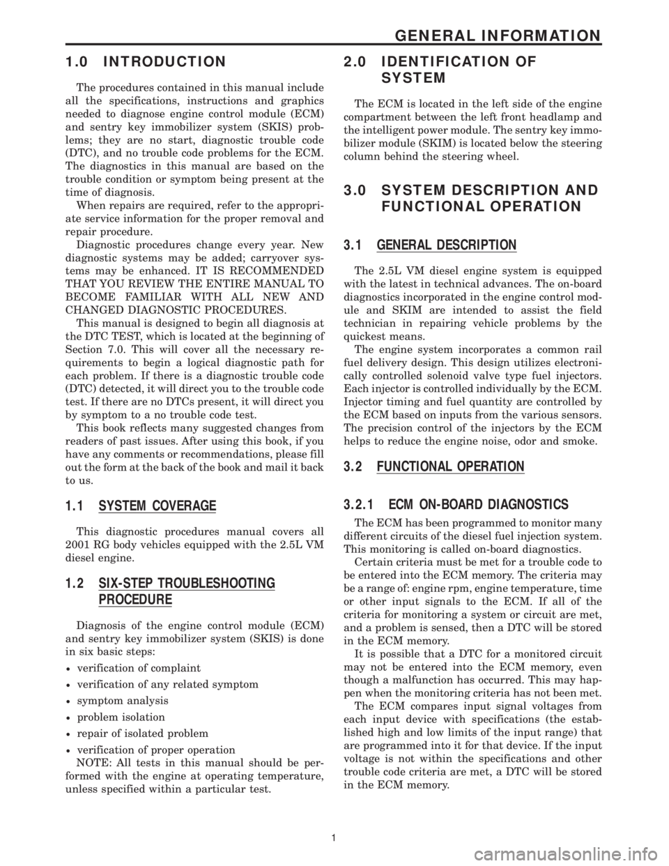
1.0 INTRODUCTION
The procedures contained in this manual include
all the specifications, instructions and graphics
needed to diagnose engine control module (ECM)
and sentry key immobilizer system (SKIS) prob-
lems; they are no start, diagnostic trouble code
(DTC), and no trouble code problems for the ECM.
The diagnostics in this manual are based on the
trouble condition or symptom being present at the
time of diagnosis.
When repairs are required, refer to the appropri-
ate service information for the proper removal and
repair procedure.
Diagnostic procedures change every year. New
diagnostic systems may be added; carryover sys-
tems may be enhanced. IT IS RECOMMENDED
THAT YOU REVIEW THE ENTIRE MANUAL TO
BECOME FAMILIAR WITH ALL NEW AND
CHANGED DIAGNOSTIC PROCEDURES.
This manual is designed to begin all diagnosis at
the DTC TEST, which is located at the beginning of
Section 7.0. This will cover all the necessary re-
quirements to begin a logical diagnostic path for
each problem. If there is a diagnostic trouble code
(DTC) detected, it will direct you to the trouble code
test. If there are no DTCs present, it will direct you
by symptom to a no trouble code test.
This book reflects many suggested changes from
readers of past issues. After using this book, if you
have any comments or recommendations, please fill
out the form at the back of the book and mail it back
to us.
1.1 SYSTEM COVERAGE
This diagnostic procedures manual covers all
2001 RG body vehicles equipped with the 2.5L VM
diesel engine.
1.2 SIX-STEP TROUBLESHOOTING
PROCEDURE
Diagnosis of the engine control module (ECM)
and sentry key immobilizer system (SKIS) is done
in six basic steps:
²verification of complaint
²verification of any related symptom
²symptom analysis
²problem isolation
²repair of isolated problem
²verification of proper operation
NOTE: All tests in this manual should be per-
formed with the engine at operating temperature,
unless specified within a particular test.
2.0 IDENTIFICATION OF
SYSTEM
The ECM is located in the left side of the engine
compartment between the left front headlamp and
the intelligent power module. The sentry key immo-
bilizer module (SKIM) is located below the steering
column behind the steering wheel.
3.0 SYSTEM DESCRIPTION AND
FUNCTIONAL OPERATION
3.1 GENERAL DESCRIPTION
The 2.5L VM diesel engine system is equipped
with the latest in technical advances. The on-board
diagnostics incorporated in the engine control mod-
ule and SKIM are intended to assist the field
technician in repairing vehicle problems by the
quickest means.
The engine system incorporates a common rail
fuel delivery design. This design utilizes electroni-
cally controlled solenoid valve type fuel injectors.
Each injector is controlled individually by the ECM.
Injector timing and fuel quantity are controlled by
the ECM based on inputs from the various sensors.
The precision control of the injectors by the ECM
helps to reduce the engine noise, odor and smoke.
3.2 FUNCTIONAL OPERATION
3.2.1 ECM ON-BOARD DIAGNOSTICS
The ECM has been programmed to monitor many
different circuits of the diesel fuel injection system.
This monitoring is called on-board diagnostics.
Certain criteria must be met for a trouble code to
be entered into the ECM memory. The criteria may
be a range of: engine rpm, engine temperature, time
or other input signals to the ECM. If all of the
criteria for monitoring a system or circuit are met,
and a problem is sensed, then a DTC will be stored
in the ECM memory.
It is possible that a DTC for a monitored circuit
may not be entered into the ECM memory, even
though a malfunction has occurred. This may hap-
pen when the monitoring criteria has not been met.
The ECM compares input signal voltages from
each input device with specifications (the estab-
lished high and low limits of the input range) that
are programmed into it for that device. If the input
voltage is not within the specifications and other
trouble code criteria are met, a DTC will be stored
in the ECM memory.
1
GENERAL INFORMATION
Page 1473 of 4284
FASTENER IDENTIFICATION
DESCRIPTION
The SAE bolt strength grades range from grade 2
to grade 8. The higher the grade number, the greater
the bolt strength. Identification is determined by the
line marks on the top of each bolt head. The actual
bolt strength grade corresponds to the number of line
marks plus 2. The most commonly used metric bolt
strength classes are 9.8 and 10.9. The metric
strength class identification number is imprinted on
the head of the bolt. The higher the class number,
the greater the bolt strength. Some metric nuts are
imprinted with a single-digit strength class on the
nut face. Refer to the Fastener Identification and
Fastener Strength Charts.
FASTENER USAGE
DESCRIPTION - FASTENER USAGE
WARNING: USE OF AN INCORRECT FASTENER
MAY RESULT IN COMPONENT DAMAGE OR PER-
SONAL INJURY.
Figure art, specifications and torque references in
this Service Manual are identified in metric and SAE
format.
During any maintenance or repair procedures, it is
important to salvage all fasteners (nuts, bolts, etc.)
for reassembly. If the fastener is not salvageable, a
fastener of equivalent specification must be used.
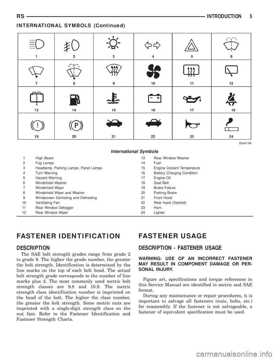
International Symbols
1 High Beam 13 Rear Window Washer
2 Fog Lamps 14 Fuel
3 Headlamp, Parking Lamps, Panel Lamps 15 Engine Coolant Temperature
4 Turn Warning 16 Battery Charging Condition
5 Hazard Warning 17 Engine Oil
6 Windshield Washer 18 Seat Belt
7 Windshield Wiper 19 Brake Failure
8 Windshield Wiper and Washer 20 Parking Brake
9 Windscreen Demisting and Defrosting 21 Front Hood
10 Ventilating Fan 22 Rear hood (Decklid)
11 Rear Window Defogger 23 Horn
12 Rear Window Wiper 24 Lighter
RSINTRODUCTION5
INTERNATIONAL SYMBOLS (Continued)
Page 1483 of 4284
FASTENER USAGE
DESCRIPTION
WARNING: USE OF AN INCORRECT FASTENER
MAY RESULT IN COMPONENT DAMAGE OR PER-
SONAL INJURY.
Figure art, specifications and torque references in
this Service Manual are identified in metric and SAE
format.
During any maintenance or repair procedures, it is
important to salvage all fasteners (nuts, bolts, etc.)
for reassembly. If the fastener is not salvageable, a
fastener of equivalent specification must be used.
THREADED HOLE REPAIR
DESCRIPTION
Most stripped threaded holes can be repaired using
a Helicoilt. Follow the vehicle or Helicoiltrecommen-
dations for application and repair procedures.
INTERNATIONAL VEHICLE
CONTROL & DISPLAY
SYMBOLS
DESCRIPTION
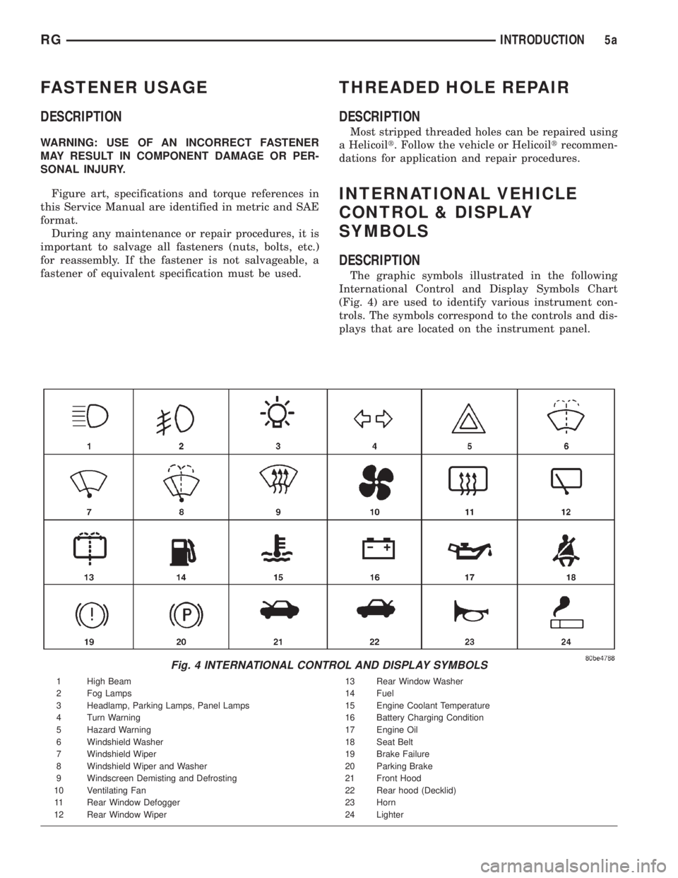
The graphic symbols illustrated in the following
International Control and Display Symbols Chart
(Fig. 4) are used to identify various instrument con-
trols. The symbols correspond to the controls and dis-
plays that are located on the instrument panel.
Fig. 4 INTERNATIONAL CONTROL AND DISPLAY SYMBOLS
1 High Beam 13 Rear Window Washer
2 Fog Lamps 14 Fuel
3 Headlamp, Parking Lamps, Panel Lamps 15 Engine Coolant Temperature
4 Turn Warning 16 Battery Charging Condition
5 Hazard Warning 17 Engine Oil
6 Windshield Washer 18 Seat Belt
7 Windshield Wiper 19 Brake Failure
8 Windshield Wiper and Washer 20 Parking Brake
9 Windscreen Demisting and Defrosting 21 Front Hood
10 Ventilating Fan 22 Rear hood (Decklid)
11 Rear Window Defogger 23 Horn
12 Rear Window Wiper 24 Lighter
RGINTRODUCTION5a
Page 1820 of 4284
FASTEN SEAT BELT LAMP OR TONE CONTINUES
FOR MORE THAN 10 SECONDS AFTER SEAT
BELTS ARE FASTENED AND DRIVER'S DOOR IS
CLOSED.
Refer to the proper Body Diagnostic Procedures
manual.
NO TONE WHEN PARK OR HEADLAMPS ARE ON
AND DRIVER'S DOOR IS OPEN.
Make sure ignition is in lock position with the key
removed.
(1) Check the BCM DTC's and BCM sensors to
verify the door is open. Repair as necessary.
(2) Actuate Chime (BCM actuates).
(3) Inspect BCM connectors and wires for proper
connection.
(4) Measure with a voltmeter the voltage (12v) on
BCM connector (PX2) pin 34 with harness connected.
DIAGNOSIS AND TESTING - DOME LAMP ON
CHIME
The dome lamp on chime will warn the driver that
the dome lamps have been left on.
When the ignition is OFF:
²Driver's door OPEN (door ajar switch is closed to
ground) and
²Dome lamps are ON (dome lamp switch is closed
to ground),
The chime will sound continuously until driver's
door is closed, dome lamps tuned OFF or until the
battery protection time out of 15 minutes has
expired. Chime rate: 168 to 192 chimes per minute.
DIAGNOSIS AND TESTING - ENGINE
TEMPERATURE CRITICAL CHIME
The engine temperature critical chime will warn
the driver that the vehicle's engine is overheating.
While monitoring the coolant temperature, the Pow-
ertrain Control Module (PCM) will send on the PCI
data bus as engine temperature every 1.376 seconds
to the cluster. The MIC calculates engine tempera-
ture and determines if a warning should occur. This
feature is functional only with the Ignition Switch in
the Run/Start position.
When the engine temperature reaches 122ÉC
(252ÉF) the MIC requests a chime from the BCM and
the engine temperature lamp comes ON. The MIC
turns OFF the lamp when the engine temperature
reaches 117ÉC (242ÉF). The MIC will chime continu-
ously (request from the BCM). The chime will turn
OFF after four minutes or when the temperature
reaches 117ÉC (242ÉF), which ever occurs first.
DIAGNOSIS AND TESTING - EXTERIOR LAMPS
ON CHIME
The exterior lamp on chime will warn the driver
that the exterior lights have been left on.
With the ignition switch OFF/key out of ignition:
²Driver's door is open (door ajar switch is closed
to ground)
²Parking lamps or headlamps ON (parking lamp
switch is closed to ground)
The chime will sound until lights are turned OFF,
driver's door closed or until the battery protection
time out of 3 minutes has expired.
Chime rate: 168 to 192 chimes per minute.
To test the exterior lamps left on function:
²Turn ignition off
²Remove ignition key
²Turn exterior lamps on with driver's door open.
Chime should sound until lamps are turned off or
driver's door is closed.
DIAGNOSIS AND TESTING - KEY-IN IGNITION
CHIME
The key-in ignition chime will act as a warning to
the driver that the ignition key has been left in the
ignition switch.
With the ignition switch is in OFF position ONLY:
²Driver's door is open/ajar (door ajar switch is
closed to ground)
²Key is in the ignition switch (ignition is in the
LOCK position)
The chime will sound until one of the above condi-
tions is removed or until battery protection time out
(15 min.) has expired. Chime rate: 168 to 192 chimes
per minute.
To test the key-in ignition function, insert key into
the ignition and open driver's door. Do not turn igni-
tion ON. Chime should sound until key is removed
from ignition or driver's door is closed.
For diagnosis and testing of the Key-In Accessory
chime, use the same testing procedure as above but
with the key in the accessory position.
DIAGNOSIS AND TESTING - LOW OIL
PRESSURE CHIME
The low oil pressure chime will warn the driver
that the engine oil pressure is low. The oil pressure
switch will close to ground during a low oil pressure
condition. The oil pressure lamp will illuminate in
the message center. The PCM will monitor the oil
pressure switch and signal a low oil pressure condi-
tion. A continuous four minute warning chime will
sound and the oil pressure lamp will come ON when
the following conditions are met:
²Ignition on and engine not cranking
8B - 2 CHIME/BUZZERRS
CHIME/BUZZER (Continued)
Page 1829 of 4284
(2) Reconnect the 24±way electrical and the pump/
motor connector. (Fig. 2)
(3) Install the battery tray (Refer to 8 - ELECTRI-
CAL/BATTERY SYSTEM/TRAY - INSTALLATION).
(4) Install the screw securing the coolant filler
neck to the battery tray.
(5) Reconnect the vacuum hose to the coolant tank
built into the battery tray.
(6) Install the battery (Refer to 8 - ELECTRICAL/
BATTERY SYSTEM/BATTERY - INSTALLATION).
(7) Reconnect the battery cables.
(8) Connect a DRBIIItto the vehicle and initialize
the system.
DATA LINK CONNECTOR
DESCRIPTION
The data link connector is located inside the vehi-
cle, below instrument panel next to the center col-
umn (Fig. 4) .
OPERATION
The data link connector (diagnostic connector)
links the DRB scan tool with the Powertrain Control
Module (PCM). Refer to On-Board Diagnostics in the
General Diagnosis section of this group.
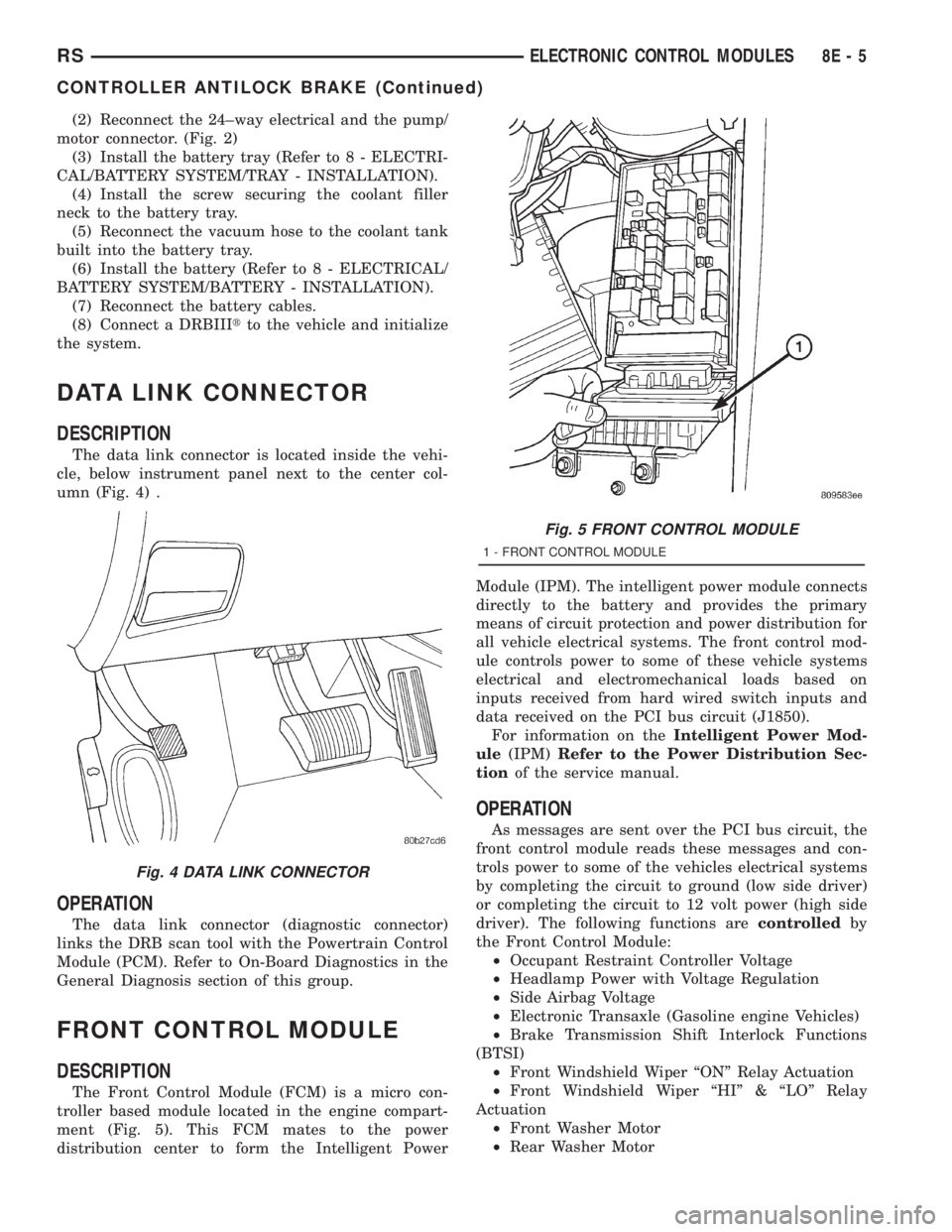
FRONT CONTROL MODULE
DESCRIPTION
The Front Control Module (FCM) is a micro con-
troller based module located in the engine compart-
ment (Fig. 5). This FCM mates to the power
distribution center to form the Intelligent PowerModule (IPM). The intelligent power module connects
directly to the battery and provides the primary
means of circuit protection and power distribution for
all vehicle electrical systems. The front control mod-
ule controls power to some of these vehicle systems
electrical and electromechanical loads based on
inputs received from hard wired switch inputs and
data received on the PCI bus circuit (J1850).
For information on theIntelligent Power Mod-
ule(IPM)Refer to the Power Distribution Sec-
tionof the service manual.
OPERATION
As messages are sent over the PCI bus circuit, the
front control module reads these messages and con-
trols power to some of the vehicles electrical systems
by completing the circuit to ground (low side driver)
or completing the circuit to 12 volt power (high side
driver). The following functions arecontrolledby
the Front Control Module:
²Occupant Restraint Controller Voltage
²Headlamp Power with Voltage Regulation
²Side Airbag Voltage
²Electronic Transaxle (Gasoline engine Vehicles)
²Brake Transmission Shift Interlock Functions
(BTSI)
²Front Windshield Wiper ªONº Relay Actuation
²Front Windshield Wiper ªHIº & ªLOº Relay
Actuation
²Front Washer Motor
²Rear Washer Motor
Fig. 4 DATA LINK CONNECTOR
Fig. 5 FRONT CONTROL MODULE
1 - FRONT CONTROL MODULE
RSELECTRONIC CONTROL MODULES8E-5
CONTROLLER ANTILOCK BRAKE (Continued)