2001 CHRYSLER VOYAGER headlamp
[x] Cancel search: headlampPage 4 of 4284
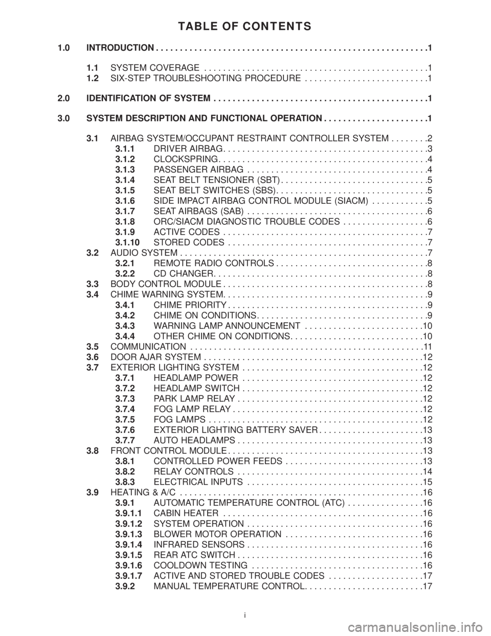
TABLE OF CONTENTS
1.0 INTRODUCTION.........................................................1
1.1SYSTEM COVERAGE...............................................1
1.2SIX-STEP TROUBLESHOOTING PROCEDURE..........................1
2.0 IDENTIFICATION OF SYSTEM.............................................1
3.0 SYSTEM DESCRIPTION AND FUNCTIONAL OPERATION......................1
3.1AIRBAG SYSTEM/OCCUPANT RESTRAINT CONTROLLER SYSTEM........2
3.1.1DRIVER AIRBAG...........................................3
3.1.2CLOCKSPRING............................................4
3.1.3PASSENGER AIRBAG......................................4
3.1.4SEAT BELT TENSIONER (SBT)...............................5
3.1.5SEAT BELT SWITCHES (SBS)................................5
3.1.6SIDE IMPACT AIRBAG CONTROL MODULE (SIACM)............5
3.1.7SEAT AIRBAGS (SAB)......................................6
3.1.8ORC/SIACM DIAGNOSTIC TROUBLE CODES..................6
3.1.9ACTIVE CODES...........................................7
3.1.10STORED CODES..........................................7
3.2AUDIO SYSTEM....................................................7
3.2.1REMOTE RADIO CONTROLS................................8
3.2.2CD CHANGER.............................................8
3.3BODY CONTROL MODULE...........................................8
3.4CHIME WARNING SYSTEM...........................................9
3.4.1CHIME PRIORITY..........................................9
3.4.2CHIME ON CONDITIONS....................................9
3.4.3WARNING LAMP ANNOUNCEMENT.........................10
3.4.4OTHER CHIME ON CONDITIONS............................10
3.5COMMUNICATION.................................................11
3.6DOOR AJAR SYSTEM..............................................12
3.7EXTERIOR LIGHTING SYSTEM......................................12
3.7.1HEADLAMP POWER......................................12
3.7.2HEADLAMP SWITCH......................................12
3.7.3PARK LAMP RELAY.......................................12
3.7.4FOG LAMP RELAY........................................12
3.7.5FOG LAMPS.............................................12
3.7.6EXTERIOR LIGHTING BATTERY SAVER......................13
3.7.7AUTO HEADLAMPS.......................................13
3.8FRONT CONTROL MODULE.........................................13
3.8.1CONTROLLED POWER FEEDS.............................13
3.8.2RELAY CONTROLS.......................................14
3.8.3ELECTRICAL INPUTS.....................................15
3.9HEATING & A/C...................................................16
3.9.1AUTOMATIC TEMPERATURE CONTROL (ATC)................16
3.9.1.1CABIN HEATER..........................................16
3.9.1.2SYSTEM OPERATION.....................................16
3.9.1.3BLOWER MOTOR OPERATION.............................16
3.9.1.4INFRARED SENSORS.....................................16
3.9.1.5REAR ATC SWITCH.......................................16
3.9.1.6COOLDOWN TESTING....................................16
3.9.1.7ACTIVE AND STORED TROUBLE CODES....................17
3.9.2MANUAL TEMPERATURE CONTROL.........................17
i
Page 14 of 4284
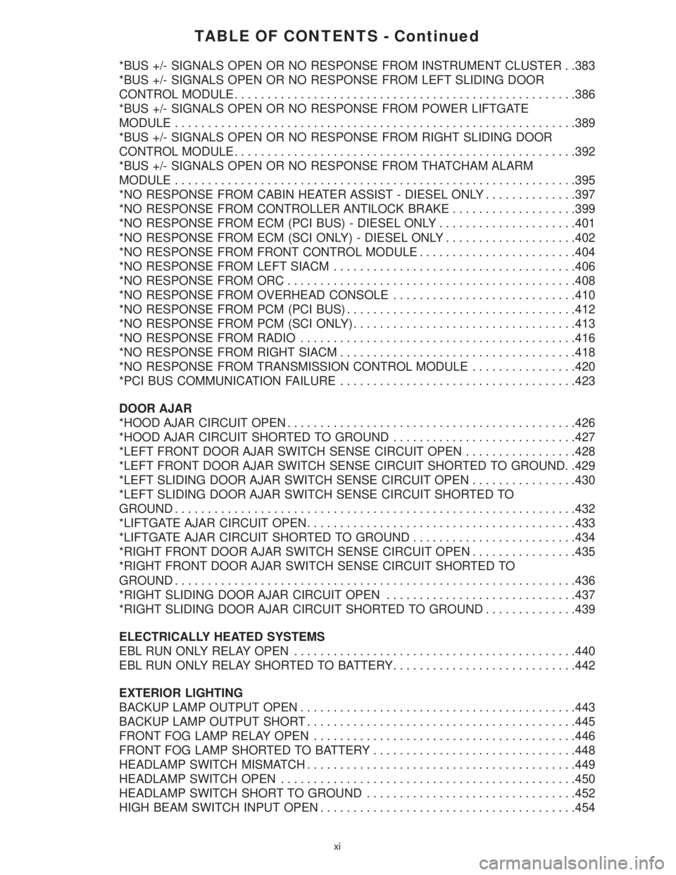
TABLE OF CONTENTS - Continued
*BUS +/- SIGNALS OPEN OR NO RESPONSE FROM INSTRUMENT CLUSTER . .383
*BUS +/- SIGNALS OPEN OR NO RESPONSE FROM LEFT SLIDING DOOR
CONTROL MODULE....................................................386
*BUS +/- SIGNALS OPEN OR NO RESPONSE FROM POWER LIFTGATE
MODULE.............................................................389
*BUS +/- SIGNALS OPEN OR NO RESPONSE FROM RIGHT SLIDING DOOR
CONTROL MODULE....................................................392
*BUS +/- SIGNALS OPEN OR NO RESPONSE FROM THATCHAM ALARM
MODULE.............................................................395
*NO RESPONSE FROM CABIN HEATER ASSIST - DIESEL ONLY..............397
*NO RESPONSE FROM CONTROLLER ANTILOCK BRAKE...................399
*NO RESPONSE FROM ECM (PCI BUS) - DIESEL ONLY.....................401
*NO RESPONSE FROM ECM (SCI ONLY) - DIESEL ONLY....................402
*NO RESPONSE FROM FRONT CONTROL MODULE........................404
*NO RESPONSE FROM LEFT SIACM.....................................406
*NO RESPONSE FROM ORC............................................408
*NO RESPONSE FROM OVERHEAD CONSOLE............................410
*NO RESPONSE FROM PCM (PCI BUS)...................................412
*NO RESPONSE FROM PCM (SCI ONLY)..................................413
*NO RESPONSE FROM RADIO..........................................416
*NO RESPONSE FROM RIGHT SIACM....................................418
*NO RESPONSE FROM TRANSMISSION CONTROL MODULE................420
*PCI BUS COMMUNICATION FAILURE....................................423
DOOR AJAR
*HOOD AJAR CIRCUIT OPEN............................................426
*HOOD AJAR CIRCUIT SHORTED TO GROUND............................427
*LEFT FRONT DOOR AJAR SWITCH SENSE CIRCUIT OPEN.................428
*LEFT FRONT DOOR AJAR SWITCH SENSE CIRCUIT SHORTED TO GROUND. .429
*LEFT SLIDING DOOR AJAR SWITCH SENSE CIRCUIT OPEN................430
*LEFT SLIDING DOOR AJAR SWITCH SENSE CIRCUIT SHORTED TO
GROUND.............................................................432
*LIFTGATE AJAR CIRCUIT OPEN.........................................433
*LIFTGATE AJAR CIRCUIT SHORTED TO GROUND.........................434
*RIGHT FRONT DOOR AJAR SWITCH SENSE CIRCUIT OPEN................435
*RIGHT FRONT DOOR AJAR SWITCH SENSE CIRCUIT SHORTED TO
GROUND.............................................................436
*RIGHT SLIDING DOOR AJAR CIRCUIT OPEN.............................437
*RIGHT SLIDING DOOR AJAR CIRCUIT SHORTED TO GROUND..............439
ELECTRICALLY HEATED SYSTEMS
EBL RUN ONLY RELAY OPEN...........................................440
EBL RUN ONLY RELAY SHORTED TO BATTERY............................442
EXTERIOR LIGHTING
BACKUP LAMP OUTPUT OPEN..........................................443
BACKUP LAMP OUTPUT SHORT.........................................445
FRONT FOG LAMP RELAY OPEN........................................446
FRONT FOG LAMP SHORTED TO BATTERY...............................448
HEADLAMP SWITCH MISMATCH.........................................449
HEADLAMP SWITCH OPEN.............................................450
HEADLAMP SWITCH SHORT TO GROUND................................452
HIGH BEAM SWITCH INPUT OPEN.......................................454
xi
Page 15 of 4284
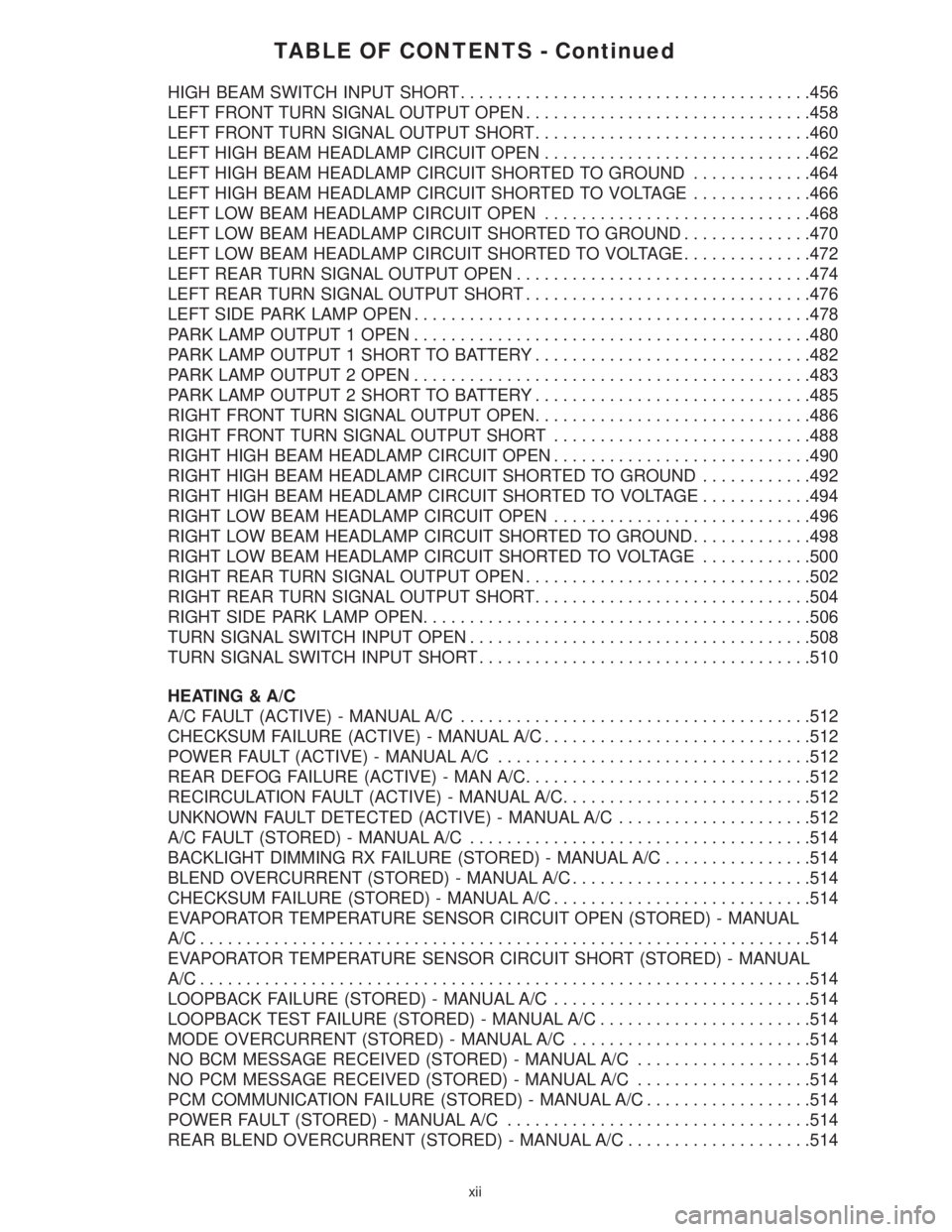
TABLE OF CONTENTS - Continued
HIGH BEAM SWITCH INPUT SHORT......................................456
LEFT FRONT TURN SIGNAL OUTPUT OPEN...............................458
LEFT FRONT TURN SIGNAL OUTPUT SHORT..............................460
LEFT HIGH BEAM HEADLAMP CIRCUIT OPEN.............................462
LEFT HIGH BEAM HEADLAMP CIRCUIT SHORTED TO GROUND.............464
LEFT HIGH BEAM HEADLAMP CIRCUIT SHORTED TO VOLTAGE.............466
LEFT LOW BEAM HEADLAMP CIRCUIT OPEN.............................468
LEFT LOW BEAM HEADLAMP CIRCUIT SHORTED TO GROUND..............470
LEFT LOW BEAM HEADLAMP CIRCUIT SHORTED TO VOLTAGE..............472
LEFT REAR TURN SIGNAL OUTPUT OPEN................................474
LEFT REAR TURN SIGNAL OUTPUT SHORT...............................476
LEFT SIDE PARK LAMP OPEN...........................................478
PARK LAMP OUTPUT 1 OPEN...........................................480
PARK LAMP OUTPUT 1 SHORT TO BATTERY..............................482
PARK LAMP OUTPUT 2 OPEN...........................................483
PARK LAMP OUTPUT 2 SHORT TO BATTERY..............................485
RIGHT FRONT TURN SIGNAL OUTPUT OPEN..............................486
RIGHT FRONT TURN SIGNAL OUTPUT SHORT............................488
RIGHT HIGH BEAM HEADLAMP CIRCUIT OPEN............................490
RIGHT HIGH BEAM HEADLAMP CIRCUIT SHORTED TO GROUND............492
RIGHT HIGH BEAM HEADLAMP CIRCUIT SHORTED TO VOLTAGE............494
RIGHT LOW BEAM HEADLAMP CIRCUIT OPEN............................496
RIGHT LOW BEAM HEADLAMP CIRCUIT SHORTED TO GROUND.............498
RIGHT LOW BEAM HEADLAMP CIRCUIT SHORTED TO VOLTAGE............500
RIGHT REAR TURN SIGNAL OUTPUT OPEN...............................502
RIGHT REAR TURN SIGNAL OUTPUT SHORT..............................504
RIGHT SIDE PARK LAMP OPEN..........................................506
TURN SIGNAL SWITCH INPUT OPEN.....................................508
TURN SIGNAL SWITCH INPUT SHORT....................................510
HEATING & A/C
A/C FAULT (ACTIVE) - MANUAL A/C......................................512
CHECKSUM FAILURE (ACTIVE) - MANUAL A/C.............................512
POWER FAULT (ACTIVE) - MANUAL A/C..................................512
REAR DEFOG FAILURE (ACTIVE) - MAN A/C...............................512
RECIRCULATION FAULT (ACTIVE) - MANUAL A/C...........................512
UNKNOWN FAULT DETECTED (ACTIVE) - MANUAL A/C.....................512
A/C FAULT (STORED) - MANUAL A/C.....................................514
BACKLIGHT DIMMING RX FAILURE (STORED) - MANUAL A/C................514
BLEND OVERCURRENT (STORED) - MANUAL A/C..........................514
CHECKSUM FAILURE (STORED) - MANUAL A/C............................514
EVAPORATOR TEMPERATURE SENSOR CIRCUIT OPEN (STORED) - MANUAL
A/C..................................................................514
EVAPORATOR TEMPERATURE SENSOR CIRCUIT SHORT (STORED) - MANUAL
A/C..................................................................514
LOOPBACK FAILURE (STORED) - MANUAL A/C............................514
LOOPBACK TEST FAILURE (STORED) - MANUAL A/C.......................514
MODE OVERCURRENT (STORED) - MANUAL A/C..........................514
NO BCM MESSAGE RECEIVED (STORED) - MANUAL A/C...................514
NO PCM MESSAGE RECEIVED (STORED) - MANUAL A/C...................514
PCM COMMUNICATION FAILURE (STORED) - MANUAL A/C..................514
POWER FAULT (STORED) - MANUAL A/C.................................514
REAR BLEND OVERCURRENT (STORED) - MANUAL A/C....................514
xii
Page 21 of 4284
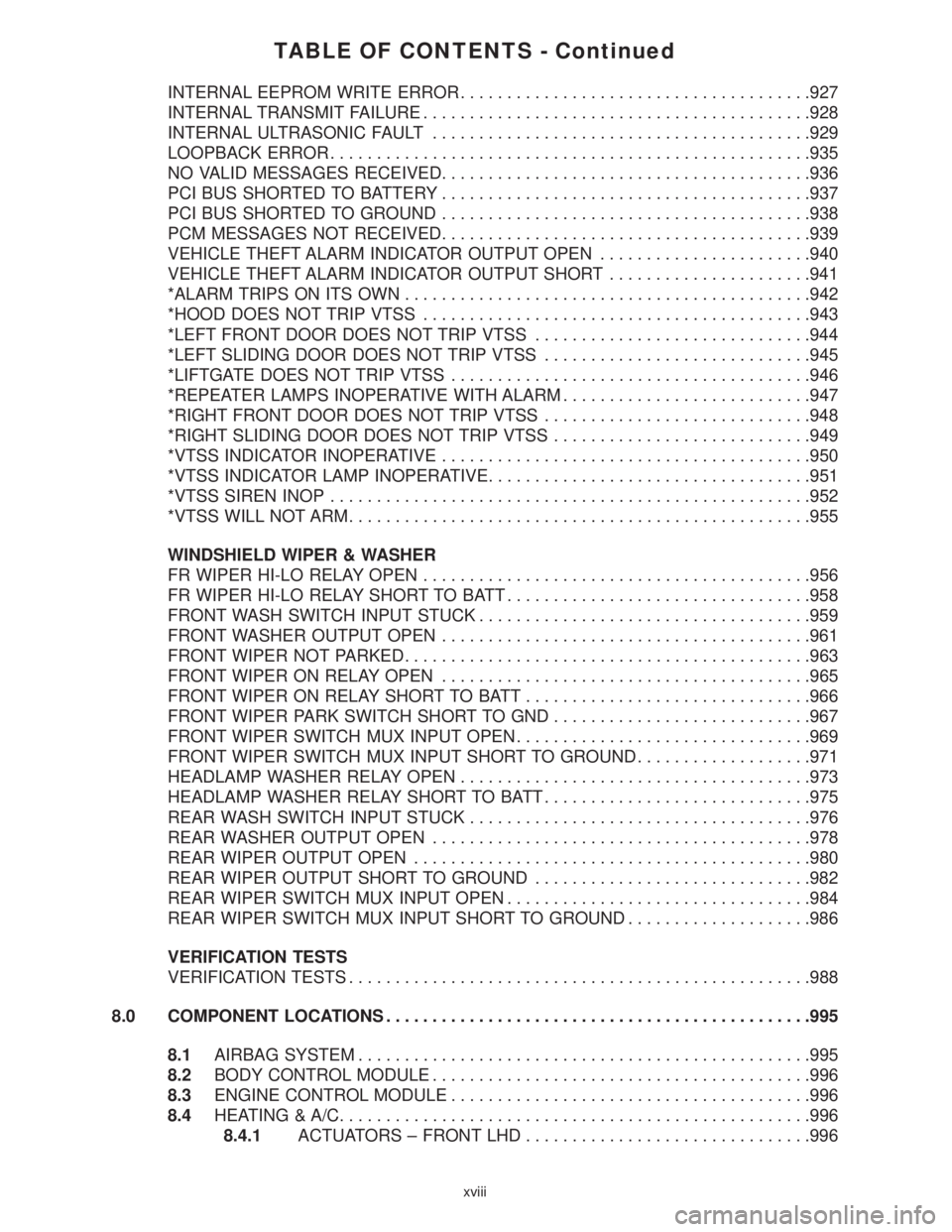
TABLE OF CONTENTS - Continued
INTERNAL EEPROM WRITE ERROR......................................927
INTERNAL TRANSMIT FAILURE..........................................928
INTERNAL ULTRASONIC FAULT.........................................929
LOOPBACK ERROR....................................................935
NO VALID MESSAGES RECEIVED........................................936
PCI BUS SHORTED TO BATTERY........................................937
PCI BUS SHORTED TO GROUND........................................938
PCM MESSAGES NOT RECEIVED........................................939
VEHICLE THEFT ALARM INDICATOR OUTPUT OPEN.......................940
VEHICLE THEFT ALARM INDICATOR OUTPUT SHORT......................941
*ALARM TRIPS ON ITS OWN............................................942
*HOOD DOES NOT TRIP VTSS..........................................943
*LEFT FRONT DOOR DOES NOT TRIP VTSS..............................944
*LEFT SLIDING DOOR DOES NOT TRIP VTSS.............................945
*LIFTGATE DOES NOT TRIP VTSS.......................................946
*REPEATER LAMPS INOPERATIVE WITH ALARM...........................947
*RIGHT FRONT DOOR DOES NOT TRIP VTSS.............................948
*RIGHT SLIDING DOOR DOES NOT TRIP VTSS............................949
*VTSS INDICATOR INOPERATIVE........................................950
*VTSS INDICATOR LAMP INOPERATIVE...................................951
*VTSS SIREN INOP....................................................952
*VTSS WILL NOT ARM..................................................955
WINDSHIELD WIPER & WASHER
FR WIPER HI-LO RELAY OPEN..........................................956
FR WIPER HI-LO RELAY SHORT TO BATT.................................958
FRONT WASH SWITCH INPUT STUCK....................................959
FRONT WASHER OUTPUT OPEN........................................961
FRONT WIPER NOT PARKED............................................963
FRONT WIPER ON RELAY OPEN........................................965
FRONT WIPER ON RELAY SHORT TO BATT...............................966
FRONT WIPER PARK SWITCH SHORT TO GND............................967
FRONT WIPER SWITCH MUX INPUT OPEN................................969
FRONT WIPER SWITCH MUX INPUT SHORT TO GROUND...................971
HEADLAMP WASHER RELAY OPEN......................................973
HEADLAMP WASHER RELAY SHORT TO BATT.............................975
REAR WASH SWITCH INPUT STUCK.....................................976
REAR WASHER OUTPUT OPEN.........................................978
REAR WIPER OUTPUT OPEN...........................................980
REAR WIPER OUTPUT SHORT TO GROUND..............................982
REAR WIPER SWITCH MUX INPUT OPEN.................................984
REAR WIPER SWITCH MUX INPUT SHORT TO GROUND....................986
VERIFICATION TESTS
VERIFICATION TESTS..................................................988
8.0 COMPONENT LOCATIONS..............................................995
8.1AIRBAG SYSTEM.................................................995
8.2BODY CONTROL MODULE.........................................996
8.3ENGINE CONTROL MODULE.......................................996
8.4HEATING & A/C...................................................996
8.4.1ACTUATORS ± FRONT LHD...............................996
xviii
Page 24 of 4284
TABLE OF CONTENTS - Continued
DIAGNOSTIC JUNCTION PORT - BLACK 16 WAY..........................1036
DOSING PUMP - BLACK 2 WAY.........................................1036
DRIVER AIRBAG C1 - BROWN 2 WAY....................................1036
DRIVER AIRBAG C2 - BLACK 2 WAY.....................................1036
DRIVER BLEND DOOR ACTUATOR (ATC) - GRAY 2 WAY...................1037
DRIVER BLEND DOOR ACTUATOR (MTC) - GRAY 2 WAY...................1037
DRIVER DOOR LOCK SWITCH - BLACK 3 WAY...........................1037
DRIVER SEAT BELT SWITCH - WHITE 2 WAY.............................1037
DRIVER SEAT BELT TENSIONER-2WAY................................1038
ELECTRIC WIPER DE-ICER C1 - WHITE 2 WAY...........................1038
ELECTRIC WIPER DE-ICER C2 - WHITE 2 WAY...........................1038
ENGINE CONTROL MODULE C1 (DIESEL) - BLACK 81 WAY.................1039
ENGINE CONTROL MODULE C2 (DIESEL) - BLACK 40 WAY.................1041
EVAPORATOR TEMPERATURE SENSOR - BLACK 2 WAY...................1041
FRONT BLOWER MODULE C1 (ATC) - BLACK 4 WAY......................1042
FRONT BLOWER MODULE C2 (ATC) - BLACK 2 WAY......................1042
FRONT READING LAMPS/SWITCH - BLACK 6 WAY........................1042
GLOVE BOX LAMP - BLUE 2 WAY.......................................1042
HALO LAMP - BLUE 2 WAY.............................................1042
HEADLAMP SWITCH - BLACK 13 WAY...................................1043
HEADLAMP WASHER PUMP MOTOR (BUILT-UP-EXPORT) - BLACK 2 WAY. . . .1043
IGNITION SWITCH - BLACK 5 WAY......................................1043
INSTRUMENT CLUSTER - BLACK 13 WAY................................1044
INTELLIGENT POWER MODULE C1 - LT. GREEN/RED 20 WAY..............1044
INTELLIGENT POWER MODULE C2 - GREEN/BLUE 10 WAY................1045
INTELLIGENT POWER MODULE C3 (DIESEL) - YELLOW/RED 20 WAY........1045
INTELLIGENT POWER MODULE C3 (GAS) - NATURAL/RED 20 WAY..........1046
INTELLIGENT POWER MODULE C4 - BLUE 10 WAY.......................1046
INTELLIGENT POWER MODULE C5 - BLACK 4 WAY.......................1046
INTELLIGENT POWER MODULE C6 - NATURAL 10 WAY....................1047
INTELLIGENT POWER MODULE C7 - BLACK/RED 20 WAY..................1047
INTELLIGENT POWER MODULE C8 - ORANGE 10 WAY....................1048
INTELLIGENT POWER MODULE C9 - BLACK 10 WAY......................1048
LEFT B-PILLAR SWITCH - GRAY 3 WAY..................................1048
LEFT CINCH/RELEASE MOTOR (POWER SLIDING DOOR) - GRAY 4 WAY.....1048
LEFT CYLINDER LOCK SWITCH - BLACK 2 WAY..........................1049
LEFT DOOR SPEAKER - BLACK/RED 6 WAY..............................1049
LEFT FOG LAMP - WHITE 2 WAY.......................................1049
LEFT FRONT DOOR AJAR SWITCH (BASE) - BLACK 2 WAY.................1049
LEFT FRONT DOOR LOCK MOTOR/AJAR SWITCH (EXCEPT BASE) -
BLACK 4 WAY........................................................1050
LEFT FRONT PARK/TURN SIGNAL LAMP (EXCEPT BUILT-UP-EXPORT) -
BLACK 3 WAY........................................................1050
LEFT FULL OPEN SWITCH (POWER SLIDING DOOR) - BLACK 2 WAY........1050
LEFT HEADLAMP (EXCEPT BUILT-UP-EXPORT) - BLACK 3 WAY.............1050
LEFT HIGH BEAM LAMP (BUILT-UP-EXPORT) - BLACK 2 WAY...............1051
LEFT INSTRUMENT PANEL SPEAKER - BLACK 2 WAY.....................1051
LEFT LOW BEAM LAMP (BUILT-UP-EXPORT) - BLACK 2 WAY...............1051
LEFT PARK LAMP (BUILT-UP-EXPORT) - BLACK 2 WAY....................1051
LEFT POWER MIRROR - BLACK 12 WAY.................................1052
LEFT REAR PILLAR SPEAKER - BLACK 2 WAY............................1052
LEFT REAR READING LAMP (LUXURY) - GRAY 3 WAY.....................1052
LEFT REAR SPEAKER - BLACK/RED 6 WAY..............................1052
xxi
Page 26 of 4284
TABLE OF CONTENTS - Continued
FRONT BLOWER MOTOR RELAY.......................................1066
FRONT CONTROL MODULE - BLACK 49 WAY.............................1067
FRONT FOG LAMP RELAY.............................................1068
HEADLAMP WASHER RELAY (BUILT-UP-EXPORT).........................1068
NAME BRAND SPEAKER RELAY........................................1068
PARK LAMP RELAY...................................................1068
POSITIVE TEMPERATURE COEFFICIENTS...............................1068
REAR BLOWER MOTOR RELAY........................................1068
POWER FOLDING MIRROR SWITCH (BUILT-UP-EXPORT) - BLACK 2 WAY. . . .1069
POWER LIFTGATE MODULE C1 - BLACK 8 WAY..........................1069
POWER LIFTGATE MODULE C2 - BLACK/RED 20 WAY.....................1069
POWER LIFTGATE MOTOR - BLACK 10 WAY.............................1070
POWER SEAT CIRCUIT BREAKER (30A) - GRAY 2 WAY....................1070
POWERTRAIN CONTROL MODULE C1 (2.4L/3.3L/3.8L) - GRAY/BLACK
40-WAY.............................................................1071
POWERTRAIN CONTROL MODULE C2 (2.4L/3.3L/3.8L) - GRAY/GRAY 40 WAY .1072
RADIO C1 - GRAY 7 WAY..............................................1073
RADIO C2 - BLACK 7 WAY.............................................1073
RADIO C3 - WHITE/RED 2 WAY.........................................1073
RADIO C4-8WAY....................................................1074
RADIO CHOKE - LT. GRAY 2 WAY.......................................1074
REAR A/C-HEATER UNIT (3 ZONE HVAC) - LT. GREEN 10 WAY..............1074
REAR AUTO TEMP CONTROL SWITCH (ATC) - BLACK 13 WAY..............1075
REAR BLOWER MOTOR POWER MODULE C1 (ATC) - RED/BLACK 4 WAY. . . .1075
REAR BLOWER MOTOR POWER MODULE C2 (ATC) - BLACK 2 WAY.........1075
REAR DOME LAMP (EXCEPT LUXURY) - GRAY 3 WAY.....................1075
REAR MODE MOTOR (ATC) - GRAY 2 WAY...............................1076
REAR TEMPERATURE MOTOR (ATC) - GRAY 2 WAY.......................1076
RECIRCULATION DOOR ACTUATOR (ATC) - GRAY 2 WAY..................1076
RECIRCULATION DOOR ACTUATOR (MTC) - GRAY 2 WAY..................1076
REMOTE KEYLESS ENTRY ANTENNA (JAPAN) - BLACK 2 WAY..............1077
REMOTE KEYLESS ENTRY MODULE - BLACK/RED 6 WAY.................1077
RIGHT B-PILLAR SWITCH - GRAY 3 WAY.................................1077
RIGHT CINCH/RELEASE MOTOR (POWER SLIDING DOOR) - GRAY 4 WAY. . . .1077
RIGHT CYLINDER LOCK SWITCH - BLACK 2 WAY.........................1078
RIGHT DOOR SPEAKER - BLACK/RED 6 WAY............................1078
RIGHT FOG LAMP - WHITE 2 WAY......................................1078
RIGHT FRONT DOOR LOCK MOTOR/AJAR SWITCH (EXCEPT BASE) -
BLACK 4 WAY........................................................1078
RIGHT FRONT PARK/TURN SIGNAL LAMP (EXCEPT BUILT-UP-EXPORT) -
BLACK 3 WAY........................................................1079
RIGHT FULL OPEN SWITCH (POWER SLIDING DOOR) - BLACK 2 WAY.......1079
RIGHT HEADLAMP (EXCEPT BUILT-UP-EXPORT) - BLACK 3 WAY............1079
RIGHT HIGH BEAM LAMP (BUILT-UP-EXPORT) - BLACK 2 WAY..............1079
RIGHT INSTRUMENT PANEL SPEAKER - BLACK 2 WAY....................1080
RIGHT LOW BEAM LAMP (BUILT-UP-EXPORT) - BLACK 2 WAY..............1080
RIGHT PARK LAMP (BUILT-UP-EXPORT) - BLACK 2 WAY...................1080
RIGHT POWER MIRROR - BLACK 12 WAY................................1080
RIGHT REAR PILLAR SPEAKER - BLACK 2 WAY..........................1081
RIGHT REAR SPEAKER - BLACK/RED 6 WAY.............................1081
RIGHT REMOTE RADIO SWITCH - BLACK 2 WAY.........................1081
RIGHT SEAT AIRBAG - YELLOW 2 WAY..................................1081
RIGHT SIDE IMPACT AIRBAG CONTROL MODULE - YELLOW/RED 7 WAY.....1081
xxiii
Page 37 of 4284
this type of system would only refer to this circuit.
A faulty speaker could not cause this DTC.
3.2.1 REMOTE RADIO CONTROLS
These radios can be controlled via remote radio
switches (optional). These switches are located on
the back side of the steering wheel. They control
mode, preset, seek up, seek down, volume up and
volume down functions.
These functions are inputs to the Body Control
Module and can be read with the DRBIIItunder
ªbody computerº. The switches are a multiplexed
signal to the BCM. The radio control MUX circuit is
a 5 volt line that is pulled to ground through
different value resistors built into the switches.
This causes a voltage drop to be seen by the BCM
and it sends a specific message to the radio on the
PCI Bus circuit. The radio then responses to the
message.
This circuit is fairly simple to troubleshoot. The
circuit must be complete from the switches in the
steering wheel to the BCM. The ground must be
complete so that the switches can cause the voltage
drop for the BCM to see. The circuit passes through
the clockspring so continuity through this devise
must be verified.
3.2.2 CD CHANGER
The new in-dash CD Changer is designed to fit
into the existing cubby bin in the center stack. This
new cartridge-less CD Changer is controlled by
your radio, and allows you to individually load up to
four discs at a time. However, due to its compact
design, the CD Changer can only carry out one
operation at a time. For example, you can not load
a new disc while playing another at the same time.
Each operation happens sequentially.
The radio unit installed with your system pro-
vides control over all features of the CD Changer
with the exception of the CD load and eject func-
tions, which are controlled by buttons located on the
front of the CD Changer. The radio also supplies the
power, ground, PCI Bus, left and right speaker
output thru a single DIN cable. All features you
would expect, such as Disc Up/Down, Track Up/
Down, Random and Scan are controlled by the
radio, which also displays all relevant CD Changer
information on the radio display.
The CD Changer contains a Load/Eject button
and an indicator light for each of the four disc
positions. The individual light indicates whether a
CD is currently loaded in that particular chamber of
the CD Changer. Pressing the individual Load/Eject
button for a particular chamber will eject a disc
currently present in that chamber. If the chamber iscurrently empty, actuating the Load/Eject button
will position that chamber to receive and load a new
disc in that chamber.
3.3 BODY CONTROL MODULE
The body control module (BCM) supplies vehicle
occupants with visual and audible information and
controls various vehicle functions. To provide and
receive information, the module is interfaced to the
vehicle's serial bus communications network (PCI).
This network consists of the powertrain control
module (PCM), the engine control module (ECM) -
diesel only, the transmission control module (TCM),
the mechanical instrument cluster (MIC), the front
control module (FCM), the occupant restraint con-
troller (ORC), the compass/mini-trip (CMTC), the
electronic vehicle information center (EVIC), the
controller antilock brake (CAB), the HVAC control
module (ATC & MTC), the power sliding door (Left
& Right) modules (PSD), the power liftgate module
(PLG), the Audio system, the side impact airbag
control (left & right) modules (SIACM), the memory
seat/mirror module (MSMM), the RKE/thatcham
alarm module and the sentry key immobilizer mod-
ule (SKIM). The BCM is operational when battery
power is supplied to the module.
The body control module provides the following
features:
²Power Door Locks
²Automatic Door Lock
²Door Lock Inhibit
²Central Locking (with VTSS Only)
²Battery Protection
²The BCM will automatically turn off all exterior
lamps after 3 minutes and all interior lamps after
15 minutes after the ignition is turned off, if they
are not turned off by the driver.
²Chime
²Compass/Minitrip Support
²Interior Lighting (Courtesy/Reading Lamps)
²BCM Diagnostic Reporting
²Electronic Liftgate Release (with Power Door
Locks)
²Exterior Lighting
²Power Folding Mirrors
²Remote Radio Controls
²Headlamp Time Delay (with/without Autohead-
lamps)
²Automatic Headlamps (with electrochromatic
mirror)
²Illuminated Entry
²Fade to Off
8
GENERAL INFORMATION
Page 41 of 4284
3.6 DOOR AJAR SYSTEM
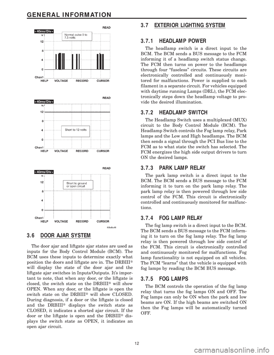
The door ajar and liftgate ajar states are used as
inputs for the Body Control Module (BCM). The
BCM uses these inputs to determine exactly what
position the doors and liftgate are in. The DRBIIIt
will display the state of the door ajar and the
liftgate ajar switches in Inputs/Outputs. It's impor-
tant to note, that when any door, or the liftgate is
closed, the switch state on the DRBIIItwill show
OPEN. When any door, or the liftgate is open the
switch state on the DRBIIItwill show CLOSED.
During diagnosis, if a door or the liftgate is closed
and the DRBIIItdisplays the switch state as
CLOSED, it indicates a shorted ajar circuit. If the
door or the liftgate is open and the DRBIIItdis-
plays the switch state as OPEN, it indicates an
open ajar circuit.
3.7 EXTERIOR LIGHTING SYSTEM
3.7.1 HEADLAMP POWER
The headlamp switch is a direct input to the
BCM. The BCM sends a BUS message to the FCM
informing it of a headlamp switch status change.
The FCM then turns on power to the headlamps
through four ªfuselessº circuits. These circuits are
electronically controlled and continuously moni-
tored for malfunctions. Power is supplied to each
filament in a separate circuit. For vehicles equipped
with daytime running Lamps (DRL), the FCM elec-
tronically steps down the headlamp voltage to pro-
vide the desired illumination.
3.7.2 HEADLAMP SWITCH
The Headlamp Switch uses a multiplexed (MUX)
circuit to the Body Control Module (BCM). The
Headlamp Switch controls the Fog lamp relay, Park
lamps and the Low and High headlamps. The BCM
then sends a signal through the PCI Bus line to the
FCM as to what state the switch has selected. The
FCM energizes the high side output drivers to turn
ON the desired lamps.
3.7.3 PARK LAMP RELAY
The park lamp switch is a direct input to the
BCM. The BCM sends a BUS message to the FCM
informing it to turn on the park lamp relay. The
park lamp relay is then powered through low side
control of the FCM. This circuit is electronically
controlled and continuously monitored for malfunc-
tions.
3.7.4 FOG LAMP RELAY
The fog lamp switch is a direct input to the BCM.
The BCM sends a BUS message to the FCM inform-
ing it to turn on the fog lamp relay. The fog lamp
relay is then powered through low side control of
the FCM. This circuit is electronically controlled
and continuously monitored for malfunctions. Fog
lamp functionality is not equipped on all vehicles.
The FCM ªlearnsº that the vehicle is equipped with
fog lamps by reading the BCM BUS message.
3.7.5 FOG LAMPS
The BCM controls the operation of the fog lamp
relay that turns the fog lamps ON and OFF. The
Fog lamps can only be ON when the park and low
beams are ON. If the high beams are switched ON
then the Fog lamps will be automatically turned
OFF.
12
GENERAL INFORMATION