2001 CHRYSLER VOYAGER jump start terminals
[x] Cancel search: jump start terminalsPage 565 of 4284

TEST ACTION APPLICABILITY
3CAUTION: The work area ambient temperature must be above 15.6ÉC (60ÉF)
to test A/C system operation.
Turn the ignition on.
With the DRBIIIt, check the PCM/ECM for DTCs.
Are any DTCs present?All
Ye s®Refer to Powertrain Diagnostic information for the related symp-
tom(s). After the repair is complete, with the DRBIIIt, erase the
DTC(s). Cycle the ignition switch. With the DRBIIIt, actuate the
Cooldown Test.
Perform BODY VERIFICATION TEST - VER 1.
No®Go To 4
4 Turn the ignition off.
Disconnect the Evaporator Temperature Sensor harness connector.
Turn the ignition on.
With the DRBIIItin Sensor Display, read the Evaporator Temperature Sensor
voltage.
Is the voltage above 4.9 volts?All
Ye s®Go To 5
No®Go To 6
5 Turn the ignition off.
Disconnect the Evaporator Temperature Sensor harness connector.
Connect a jumper wire between the Evaporator Temperature Sensor Signal circuit
and the Sensor Ground circuit at the Evaporator Temperature Sensor harness
connector.
Turn the ignition on.
With the DRBIIItin Sensor Display, read the Evaporator Temperature Sensor
voltage.
Is the voltage 0.0 volts?All
Ye s®Replace the Evaporator Temperature Sensor in accordance with
the Service Information. After repair is complete, rerun the
Cooldown Test.
Perform BODY VERIFICATION TEST - VER 1.
No®Go To 6
6NOTE: Ensure that the voltmeter leads meet the terminals in the connector
and that there is good terminal to wire connection.
NOTE: Ensure the voltmeter leads are connected for positive polarity.
Back probe the Sensor Ground circuit between the Evaporator Temperature Sensor
harness connector and the A/C - Heater Control Module C1 harness connector.
Turn the ignition on.
Is the voltage below 0.10 volt?All
Ye s®Go To 7
No®Repair the high resistance in the Sensor Ground circuit. After
repair is complete, rerun the Cooldown Test.
Perform BODY VERIFICATION TEST - VER 1.
536
HEATING & A/C
COOLDOWN TEST TOO COLD TO START - MANUAL A/C ÐContinued
Page 1227 of 4284

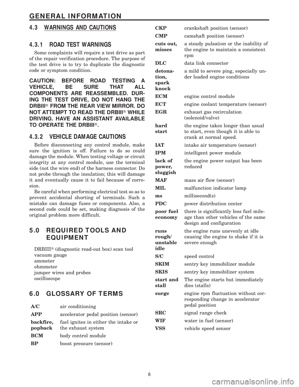
4.3 WARNINGS AND CAUTIONS
4.3.1 ROAD TEST WARNINGS
Some complaints will require a test drive as part
of the repair verification procedure. The purpose of
the test drive is to try to duplicate the diagnostic
code or symptom condition.
CAUTION: BEFORE ROAD TESTING A
VEHICLE, BE SURE THAT ALL
COMPONENTS ARE REASSEMBLED. DUR-
ING THE TEST DRIVE, DO NOT HANG THE
DRBIIITFROM THE REAR VIEW MIRROR. DO
NOT ATTEMPT TO READ THE DRBIIITWHILE
DRIVING. HAVE AN ASSISTANT AVAILABLE
TO OPERATE THE DRBIIIT.
4.3.2 VEHICLE DAMAGE CAUTIONS
Before disconnecting any control module, make
sure the ignition is off. Failure to do so could
damage the module. When testing voltage or circuit
integrity at any control module, use the terminal
side (not the wire end) of the harness connector. Do
not probe through the insulation; this will damage
it and eventually cause it to fail because of corro-
sion.
Be careful when performing electrical test so as to
prevent accidental shorting of terminals. Such a
mistake can damage fuses or components. Also, a
second code could be set, making diagnosis of the
original problem more difficult.
5.0 REQUIRED TOOLS AND
EQUIPMENT
DRBIIIt(diagnostic read-out box) scan tool
vacuum gauge
ammeter
ohmmeter
jumper wires and probes
oscilloscope
6.0 GLOSSARY OF TERMS
A/Cair conditioning
APPaccelerator pedal position (sensor)
backfire,
popbackfuel ignites in either the intake or
the exhaust system
BCMbody control module
BPboost pressure (sensor)CKPcrankshaft position (sensor)
CMPcamshaft position (sensor)
cuts out,
missesa steady pulsation or the inability of
the engine to maintain a consistent
rpm
DLCdata link connector
detona-
tion,
spark
knocka mild to severe ping, especially un-
der loaded engine conditions
ECMengine control module
ECTengine coolant temperature (sensor)
EGRexhaust gas recirculation
(solenoid/valve)
hard
startthe engine takes longer than usual
to start, even though it is able to
crank at normal speed.
IATintake air temperature (sensor)
IPMintelligent power module
lack of
power,
sluggishthe engine power output has been
reduced
MAFmass air flow (sensor)
MILmalfunction indicator lamp
msmillisecond(s)
PDCpower distribution center
poor fuel
economythere is significantly less fuel mile-
age than other vehicles of the same
design and configuration
runs
rough/
unstable
idlethe engine runs unevenly at idle
causing the engine to shake if it is
severe enough
S/Cspeed control
SKIMsentry key immobilizer module
SKISsentry key immobilizer system
start and
stallThe engine starts but immediately
dies (stalls)
surgeengine rpm fluctuation without cor-
responding change in accelerator
pedal position
SRCsignal range check
WIFwater in fuel (sensor)
VSSvehicle speed sensor
8
GENERAL INFORMATION
Page 1884 of 4284

(5) Connect a remote starter switch or a jumper
wire between the remote battery positive post and
terminal 87 of the starter relay connector.
(a) If engine cranks, starter/starter solenoid is
good. Go to the Starter Relay Test.
(b) If engine does not crank or solenoid chatters,
check wiring and connectors from starter relay to
starter solenoid for loose or corroded connections.
Particularly at starter terminals.
(c) Repeat test. If engine still fails to crank prop-
erly, trouble is within starter or starter mounted
solenoid, and replace starter.
STARTER RELAY
WARNING: CHECK TO ENSURE THAT THE TRANS-
MISSION IS IN THE PARK/NEUTRAL POSITION
WITH THE PARKING BRAKE APPLIED.
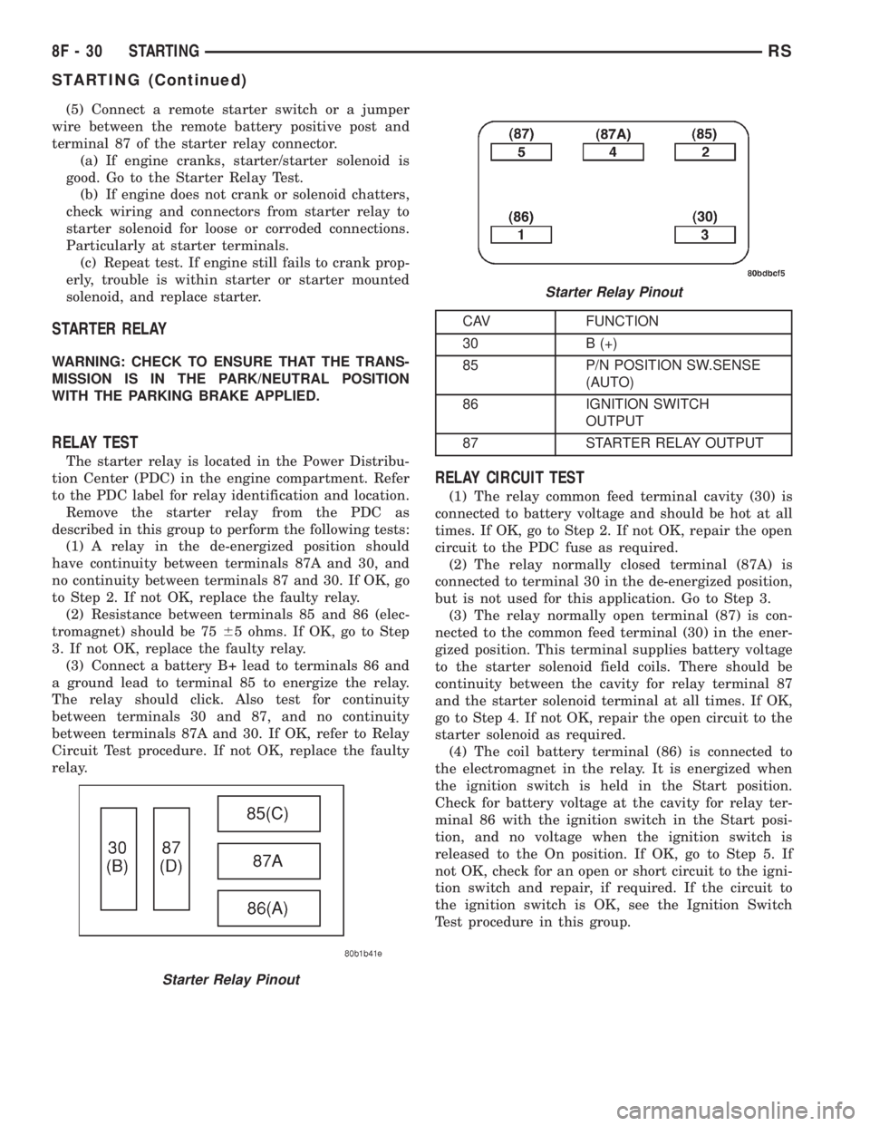
RELAY TEST
The starter relay is located in the Power Distribu-
tion Center (PDC) in the engine compartment. Refer
to the PDC label for relay identification and location.
Remove the starter relay from the PDC as
described in this group to perform the following tests:
(1) A relay in the de-energized position should
have continuity between terminals 87A and 30, and
no continuity between terminals 87 and 30. If OK, go
to Step 2. If not OK, replace the faulty relay.
(2) Resistance between terminals 85 and 86 (elec-
tromagnet) should be 7565 ohms. If OK, go to Step
3. If not OK, replace the faulty relay.
(3) Connect a battery B+ lead to terminals 86 and
a ground lead to terminal 85 to energize the relay.
The relay should click. Also test for continuity
between terminals 30 and 87, and no continuity
between terminals 87A and 30. If OK, refer to Relay
Circuit Test procedure. If not OK, replace the faulty
relay.
CAV FUNCTION
30 B (+)
85 P/N POSITION SW.SENSE
(AUTO)
86 IGNITION SWITCH
OUTPUT
87 STARTER RELAY OUTPUT
RELAY CIRCUIT TEST
(1) The relay common feed terminal cavity (30) is
connected to battery voltage and should be hot at all
times. If OK, go to Step 2. If not OK, repair the open
circuit to the PDC fuse as required.
(2) The relay normally closed terminal (87A) is
connected to terminal 30 in the de-energized position,
but is not used for this application. Go to Step 3.
(3) The relay normally open terminal (87) is con-
nected to the common feed terminal (30) in the ener-
gized position. This terminal supplies battery voltage
to the starter solenoid field coils. There should be
continuity between the cavity for relay terminal 87
and the starter solenoid terminal at all times. If OK,
go to Step 4. If not OK, repair the open circuit to the
starter solenoid as required.
(4) The coil battery terminal (86) is connected to
the electromagnet in the relay. It is energized when
the ignition switch is held in the Start position.
Check for battery voltage at the cavity for relay ter-
minal 86 with the ignition switch in the Start posi-
tion, and no voltage when the ignition switch is
released to the On position. If OK, go to Step 5. If
not OK, check for an open or short circuit to the igni-
tion switch and repair, if required. If the circuit to
the ignition switch is OK, see the Ignition Switch
Test procedure in this group.
Starter Relay Pinout
Starter Relay Pinout
8F - 30 STARTINGRS
STARTING (Continued)
Page 3806 of 4284

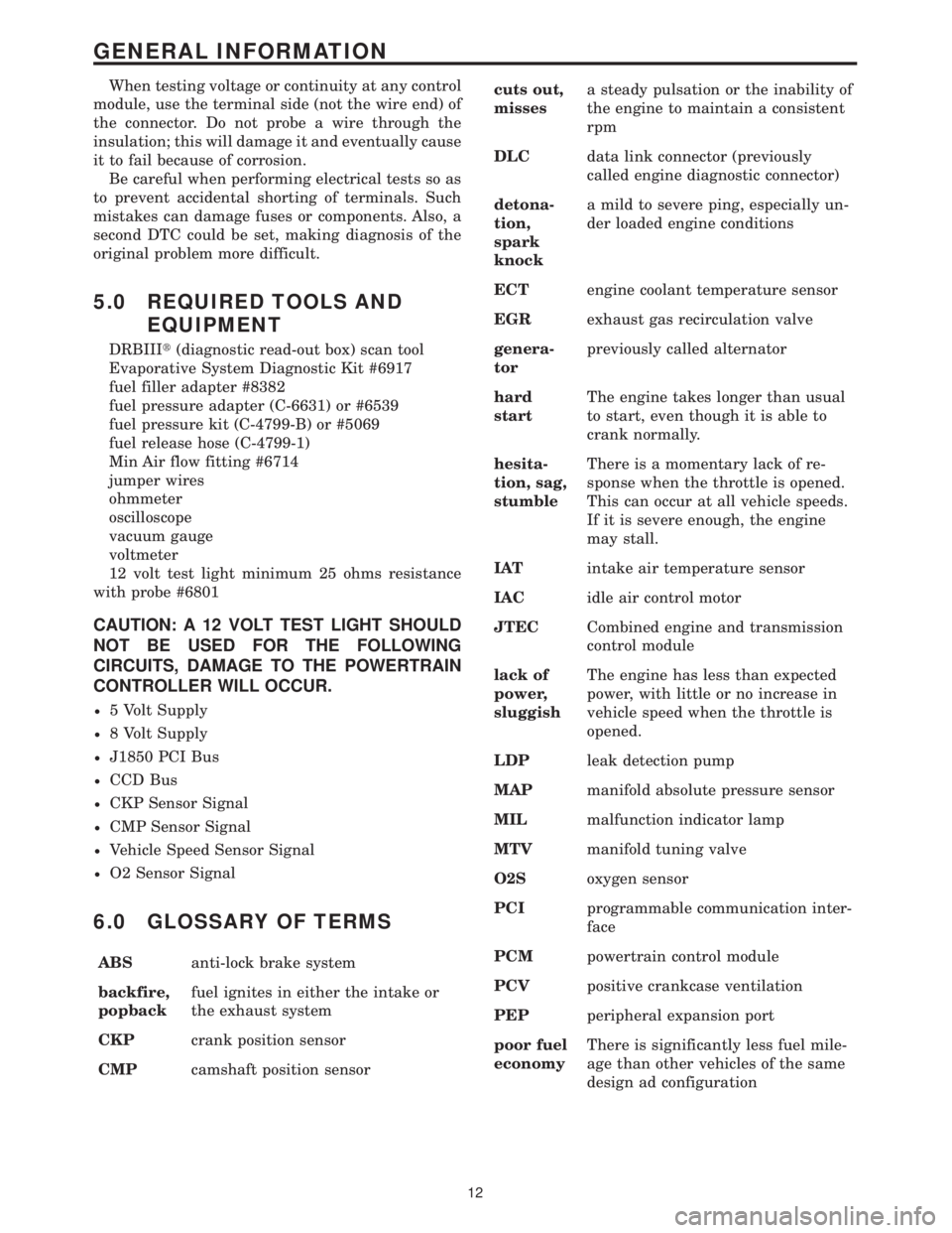
When testing voltage or continuity at any control
module, use the terminal side (not the wire end) of
the connector. Do not probe a wire through the
insulation; this will damage it and eventually cause
it to fail because of corrosion.
Be careful when performing electrical tests so as
to prevent accidental shorting of terminals. Such
mistakes can damage fuses or components. Also, a
second DTC could be set, making diagnosis of the
original problem more difficult.
5.0 REQUIRED TOOLS AND
EQUIPMENT
DRBIIIt(diagnostic read-out box) scan tool
Evaporative System Diagnostic Kit #6917
fuel filler adapter #8382
fuel pressure adapter (C-6631) or #6539
fuel pressure kit (C-4799-B) or #5069
fuel release hose (C-4799-1)
Min Air flow fitting #6714
jumper wires
ohmmeter
oscilloscope
vacuum gauge
voltmeter
12 volt test light minimum 25 ohms resistance
with probe #6801
CAUTION: A 12 VOLT TEST LIGHT SHOULD
NOT BE USED FOR THE FOLLOWING
CIRCUITS, DAMAGE TO THE POWERTRAIN
CONTROLLER WILL OCCUR.
²5 Volt Supply
²8 Volt Supply
²J1850 PCI Bus
²CCD Bus
²CKP Sensor Signal
²CMP Sensor Signal
²Vehicle Speed Sensor Signal
²O2 Sensor Signal
6.0 GLOSSARY OF TERMS
ABSanti-lock brake system
backfire,
popbackfuel ignites in either the intake or
the exhaust system
CKPcrank position sensor
CMPcamshaft position sensorcuts out,
missesa steady pulsation or the inability of
the engine to maintain a consistent
rpm
DLCdata link connector (previously
called engine diagnostic connector)
detona-
tion,
spark
knocka mild to severe ping, especially un-
der loaded engine conditions
ECTengine coolant temperature sensor
EGRexhaust gas recirculation valve
genera-
torpreviously called alternator
hard
startThe engine takes longer than usual
to start, even though it is able to
crank normally.
hesita-
tion, sag,
stumbleThere is a momentary lack of re-
sponse when the throttle is opened.
This can occur at all vehicle speeds.
If it is severe enough, the engine
may stall.
IATintake air temperature sensor
IACidle air control motor
JTECCombined engine and transmission
control module
lack of
power,
sluggishThe engine has less than expected
power, with little or no increase in
vehicle speed when the throttle is
opened.
LDPleak detection pump
MAPmanifold absolute pressure sensor
MILmalfunction indicator lamp
MTVmanifold tuning valve
O2Soxygen sensor
PCIprogrammable communication inter-
face
PCMpowertrain control module
PCVpositive crankcase ventilation
PEPperipheral expansion port
poor fuel
economyThere is significantly less fuel mile-
age than other vehicles of the same
design ad configuration
12
GENERAL INFORMATION