2001 CHRYSLER VOYAGER seats
[x] Cancel search: seatsPage 34 of 4284
CAUTION: Deployed Front Air Bags may or may not have live pyrotechnic material within the
air bag inflator. Do not dispose of 2001 Mopar Year Driver and Passenger Airbags unless you
are sure of complete deployment. Please refer to the Hazardous Substance Control System for
Proper Disposal. Dispose of deployed air bags in a manner consistent with state, provincial,
local, and federal regulations. Use the following table to identify the status of the Airbag Squib.
AIRBAG SQUIB STATUS
(1) Using a DRBIIItread Airbag DTC'sIfthe following active codes are present:
ACTIVE DTC CONDITIONS SQUIB STATUS
Passenger Squib 1 open
Passenger Squib 2 openCheck the stored DTC'sAND IFthe stored min-
utes for both are within 15 minutes of each other.Both Passenger Squib 1
and 2 were used.
Passenger Squib 1 open
Passenger Squib 2 openCheck the stored DTC'sAND IFthe stored min-
utes for Passenger Squib 2 open is GREATER
than the stored minutes for Passenger Squib 1 by
15 minutes or more.Passenger Squib 1 was
used; Passenger Squib
2 is live.
Passenger Squib 1 open
Passenger Squib 2 openCheck the stored DTC'sAND IFthe stored min-
utes for Passenger Squib 1 open is GREATER
than the stored minutes for Driver Squib 2 by 15
minutes or more.Passenger Squib 1 is
live; Driver Squib 2
was used.
IfPassenger Squib 1
openAND IFPassenger Squib 2 open is NOT an ac-
tive code.Passenger Squib 1 was
used; Passenger Squib
2 is live.
IfPassenger Squib 2
openAND IFPassenger Squib 1 open is NOT an ac-
tive code.Passenger Squib 1 is
live; Passenger Squib 2
was used.
Ifneither of the following codes is an active code:
ACTIVE DTC SQUIB STATUS
Passenger squib 1 open Status of Airbag is
Passenger squib 2 open Unknown.
3.1.4 SEAT BELT TENSIONER (SBT)
The driver and passenger seat belt (buckle) ten-
sioners are mounted to the inboard side of the front
seats. The seat belt buckle and seat belt switch are
connected directly to the seat belt tensioner cable.
At the onset of an impact event the ORC uses the
seat belt tensioner to rapidly retract the seat belt
buckles. With the slack removed, the occupant's
forward motion in an impact will be reduced as will
the likelihood of contacting interior components.
The seat belt tensioner cannot be removed, the
occupant's forward motion in an impact will be
reduced as will the likelihood of contacting re-
paired, if damaged or defective it must be replaced.
The ORC continuously monitors the resistance of
the seat belt tensioner circuits an open or shorted
conditions.
3.1.5 SEAT BELT SWITCHES (SBS)
The hall-effect driver and front passenger seat
belt switches provide the seat belt status, buckledor unbuckled, via hardwired inputs to the ORC. The
ORC uses seat belt switch inputs to determine the
appropriate level of airbag deployment. If the seat
belt switches are damaged or defective the seat belt
tensioner must be replaced. The ORC continuously
monitors the seat belt switch circuits for an open or
shorted conditions.
3.1.6 SIDE IMPACT AIRBAG CONTROL
MODULE (SIACM)
Supplemental driver and front passenger seat
airbags provide side impact protection for the front
seat occupants. Each side airbag has it own side
impact airbag control module (SIACM) to provide
independent impact sensing and deployment. SI-
ACM are located on the left and right B post just
above the seat belt retractor. One, same part num-
ber, side impact airbag control module (SIACM) is
used on both side of the vehicle. However, for proper
PCI bus operation each SIACM must have a unique
module identification. To provide the unique mod-
ule identification for both, left and right, the
SIACM software looks for a ground on cavity 5 of
the SIACM connector. If cavity 5 is grounded the
SIACM communicates as a left SIACM otherwise it
communicates as a right SIACM. The SIACM per-
forms self diagnostics and circuit tests to determine
5
GENERAL INFORMATION
Page 46 of 4284
± Evap Temp Sensor Shorted
± Evap Temp Sensor Open
± A/C Pressure Too Low
± A/C Pressure Too High
± Invalid Conditions for Cooldown Test, Evap
Temperature Too Low
If a message other than Cooldown Test Passed
occurs, refer to the appropriate symptom for diag-
nosis.
3.9.1.7 ACTIVE AND STORED TROUBLE
CODES
The Automatic Temperature Control (ATC) is
capable of storing Active and Stored trouble codes.
Active codes indicate a current fault in the system.
Stored codes indicate that a problem has occurred
in the system, however is not currently present.
Active codes cannot be erased until the problem
causing the code has been repaired. At this time the
Active code is converted to a Stored code, which can
be erased using the DRBIIIt.
3.9.2 MANUAL TEMPERATURE CONTROL
3.9.2.1 SYSTEM AVAILABILITY
Depending on the model, either a Single-Zone Air
Conditioning System or a Dual-Zone Air Condition-
ing System is currently available in these vehicles.
3.9.2.2 CABIN HEATER
For Vehicles equipped with a diesel engine, a
Cabin Heater is used in conjunction with the HVAC
system. The Cabin Heater is designed to supply the
vehicle's occupants with heat prior to the engine
reaching operating temperature. For additional in-
formation on this system, refer to Cabin Heater
under General Information and Diagnostic Proce-
dures in this manual.
3.9.2.3 ZONE CONTROL ± SINGLE-ZONE
The Single-Zone Air Conditioning System main-
tains incoming air temperature, airflow, fan speed,
and fresh air intake for the entire vehicle from the
instrument panel mounted A/C ± Heater Control
Module. The full range of temperature that the
system can produce in any mode for the entire
vehicle is available by positioning the blend control
to the desired range.
3.9.2.4 ZONE CONTROL ± DUAL-ZONE
The Dual-Zone Air Conditioning System main-
tains incoming air temperature, airflow, fan speed,
and fresh air intake for the entire vehicle from the
instrument panel mounted A/C ± Heater ControlModule. In addition, this system provides com-
pletely independent side-to-side control of incoming
air temperature. The full range of temperature that
the system can produce in any mode is available on
either side of the vehicle by positioning the inde-
pendent driver and passenger blend controls to the
desired range.
3.9.2.5 AIR DISTRIBUTION
The HVAC unit has five fully adjustable instru-
ment panel outlets. Side-window demister outlets
in the instrument panel eliminate door ducts and
door-to-instrument panel seals. A single, central
mounted outlet delivers air for defrosting the wind-
shield. Air exhausters allow air entering at the
front of the vehicle to flow out the back to the rear
occupants. Mid-cabin comfort control directs only
cooling air flow to the intermediate seat occupants
through outlets at the rear of each front door trim
panel. Air is supplied to these outlets from the
instrument panel through ducts in the doors that
use molded seals at the instrument panel to prevent
air leakage. Wide outlets under the front seats with
directional dividers distribute heated air across the
floor to the intermediate seat occupants. Ducts in
the center of the vehicle under the carpet deliver air
from the HVAC unit to these outlets. Models
equipped with Dual-Zone A/C systems also include
a dust and odor air filter installed in the HAVC
housing.
3.9.2.6 DOOR ACTUATORS
The electric door actuators are a two-wire design.
Each door actuator uses a similar connector wired
directly to the A/C ± Heater Control Module. Single-
Zone systems have one blend door actuator, one
mode door actuator, and one recirculation door
actuator. Dual-Zone systems have two blend door
actuators, one mode door actuator, and one recircu-
lation door actuator. All of the door actuators are
accessible from the vehicle's interior.
3.9.2.7 DOOR ACTUATOR CONTROL
The A/C ± Heater Control Module knows the
number of operating actuator revolutions required
for full door travel as well as the number of actuator
commutator pulses per revolution. Using these pa-
rameters, the A/C ± Heater Control Module runs
the actuator for the number of commutator pulses
that correspond to the desired door position. To
maintain accuracy, the system recalibrates itself
periodically at known zero and full travel condi-
tions.
17
GENERAL INFORMATION
Page 1540 of 4284
(7) Install the jounce bumper on the strut shaft
(Fig. 39). The jounce bumper is to be installed with
the small end pointing downward.
(8) Install the dust shield on the strut. Collapse
and stretch the dust shield down over the top of the
jounce bumper until the dust shield snaps into the
slot on the jounce bumper. The jounce bumper will be
at the top of the inner dust boot. Return the dust
shield to its fully extended length.
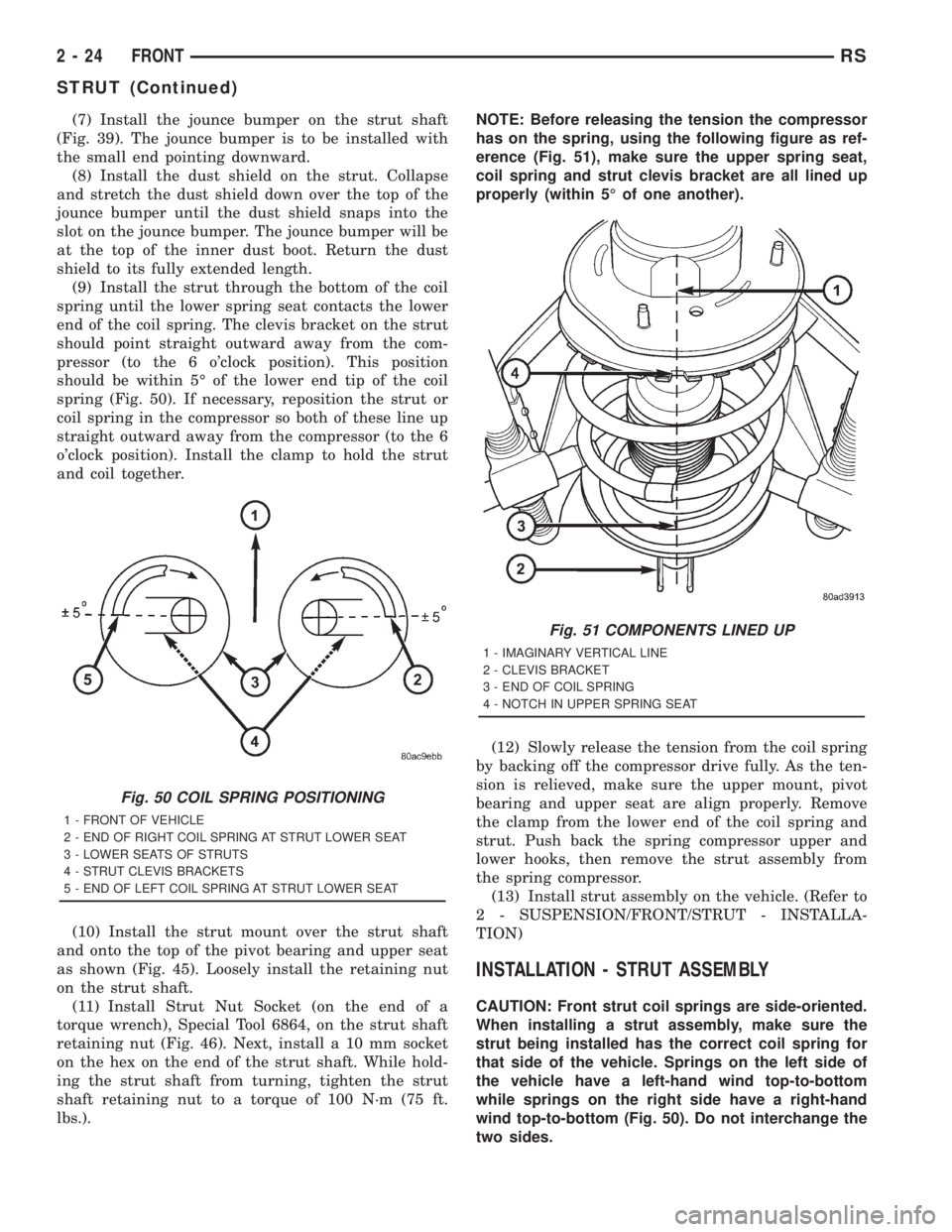
(9) Install the strut through the bottom of the coil
spring until the lower spring seat contacts the lower
end of the coil spring. The clevis bracket on the strut
should point straight outward away from the com-
pressor (to the 6 o'clock position). This position
should be within 5É of the lower end tip of the coil
spring (Fig. 50). If necessary, reposition the strut or
coil spring in the compressor so both of these line up
straight outward away from the compressor (to the 6
o'clock position). Install the clamp to hold the strut
and coil together.
(10) Install the strut mount over the strut shaft
and onto the top of the pivot bearing and upper seat
as shown (Fig. 45). Loosely install the retaining nut
on the strut shaft.
(11) Install Strut Nut Socket (on the end of a
torque wrench), Special Tool 6864, on the strut shaft
retaining nut (Fig. 46). Next, install a 10 mm socket
on the hex on the end of the strut shaft. While hold-
ing the strut shaft from turning, tighten the strut
shaft retaining nut to a torque of 100 N´m (75 ft.
lbs.).NOTE: Before releasing the tension the compressor
has on the spring, using the following figure as ref-
erence (Fig. 51), make sure the upper spring seat,
coil spring and strut clevis bracket are all lined up
properly (within 5É of one another).
(12) Slowly release the tension from the coil spring
by backing off the compressor drive fully. As the ten-
sion is relieved, make sure the upper mount, pivot
bearing and upper seat are align properly. Remove
the clamp from the lower end of the coil spring and
strut. Push back the spring compressor upper and
lower hooks, then remove the strut assembly from
the spring compressor.
(13) Install strut assembly on the vehicle. (Refer to
2 - SUSPENSION/FRONT/STRUT - INSTALLA-
TION)
INSTALLATION - STRUT ASSEMBLY
CAUTION: Front strut coil springs are side-oriented.
When installing a strut assembly, make sure the
strut being installed has the correct coil spring for
that side of the vehicle. Springs on the left side of
the vehicle have a left-hand wind top-to-bottom
while springs on the right side have a right-hand
wind top-to-bottom (Fig. 50). Do not interchange the
two sides.
Fig. 50 COIL SPRING POSITIONING
1 - FRONT OF VEHICLE
2 - END OF RIGHT COIL SPRING AT STRUT LOWER SEAT
3 - LOWER SEATS OF STRUTS
4 - STRUT CLEVIS BRACKETS
5 - END OF LEFT COIL SPRING AT STRUT LOWER SEAT
Fig. 51 COMPONENTS LINED UP
1 - IMAGINARY VERTICAL LINE
2 - CLEVIS BRACKET
3 - END OF COIL SPRING
4 - NOTCH IN UPPER SPRING SEAT
2 - 24 FRONTRS
STRUT (Continued)
Page 1660 of 4284
For information on master cylinder application,
bore and type, view the following table:
BRAKE SYSTEMMASTER CYLINDER
BORE/TYPE
Disc/Drum - ABS23.8 mm Conventional
Compensating Port
Disc/Drum - Non-ABS23.8 mm Conventional
Compensating Port
Disc/Disc - ABS25.4 mm (1-1/16 in.)
Conventional
Compensating Port
Disc/Disc ABS With
Traction Control25.4 mm (1-1/16 in.) Dual
Center Port
CAUTION: When replacing a master cylinder, be
sure to use the correct master cylinder for the type
of brake system the vehicle is equipped with.
The body of the master cylinder is an anodized alu-
minum casting. It has a machined bore to accept the
master cylinder pistons and threaded ports with
seats for the hydraulic brake line connections.
The brake fluid reservoir is mounted on the top of
the master cylinder. It is made of a see-through
polypropylene type plastic for easy fluid level view-
ing. A brake fluid level switch is attached to the
brake fluid reservoir.
The master cylinder is not a repairable component
and must be replaced if diagnosed to be functioning
improperly. The brake fluid reservoir and brake fluid
level switch can be replaced separately.
CAUTION: Do not hone the bore of the cylinder as
this will remove the anodized surface from the bore.
OPERATION
When the brake pedal is depressed, the master cyl-
inder primary and secondary pistons apply brake
pressure through the chassis tubes to the brakes at
each tire and wheel assembly.
The master cylinder primary outlet port supplies
hydraulic pressure to the right front and left rear
brakes. The secondary outlet port supplies hydraulic
pressure to the left front and right rear brakes.
STANDARD PROCEDURE - MASTER CYLINDER
BLEEDING
CAUTION: When clamping master cylinder in vise,
only clamp master cylinder by its mounting flange,
do not clamp on primary piston, seal or body of
master cylinder.(1) Clamp the master cylinder in a vise using only
the mounting flange.
NOTE: Two different size bleeding tubes need to be
used depending on which type of master cylinder
the vehicle is equipped with. Vehicles equipped
with traction control have different size brake tubes
and nuts at the master cylinder than the non-trac-
tion control equipped vehicles. Be sure the correct
size bleeding tubes are used when bleeding the
master cylinder.
(2) Thread Bleeding Tubes, Special Tool 8358, for a
non-traction control master cylinder or Special Tool
8129 for a traction control master cylinder into mas-
ter cylinder primary and secondary ports. Position
outlet ends of bleeding tubes in reservoir with the
outlets below surface of brake fluid when reservoir is
filled to its proper level.
(3) Fill brake fluid reservoir with Mopartbrake
fluid or equivalent conforming to DOT 3 (DOT 4 and
DOT 4+ are acceptable) specifications.
(4) Using a wooden dowel, depress push rod slowly,
and then allow pistons to return to released position.
Repeat several times until all air bubbles are
expelled from master cylinder.
(5) Remove bleeding tubes from master cylinder
outlet ports, and then plug outlet ports and install
fill cap on reservoir.
(6) Remove master cylinder from vise.
(7) Install the filler cap on master cylinder fluid
reservoir.
(8) Install master cylinder. (Refer to 5 - BRAKES -
BASE/HYDRAULIC/MECHANICAL/MASTER CYL-
INDER - INSTALLATION)
REMOVAL - MASTER CYLINDER
CAUTION: Vacuum in the power brake booster must
be pumped down (removed) before removing mas-
ter cylinder from power brake booster. This is nec-
essary to prevent the power brake booster from
sucking in any contamination as the master cylin-
der is removed. This can be done simply by pump-
ing the brake pedal, with the vehicle's engine not
running, until a firm feeling brake pedal is achieved.
(1) With engine not running, pump brake pedal
until a firm pedal is achieved (4-5 strokes).
(2) Disconnect negative battery terminal.
(3) Disconnect positive battery terminal.
(4) Remove battery shield.
(5) Remove nut and clamp securing battery to tray,
remove battery.
5 - 34 BRAKES - BASERS
MASTER CYLINDER (Continued)
Page 1712 of 4284
ROTORS
SPECIFICATIONS
BRAKE ROTOR
NOTE: Use the following information on all 4 wheel
disc brake vehicles that are equipped with BR3
sales code.When refacing a rotor, the required TIR (Total
Indicator Reading) and thickness variation limits
MUST BE MAINTAINED. Extreme care in the oper-
ation of rotor turning equipment is required.
SPECIFICATIONS/LIMITS
Brake
RotorRotor ThicknessMinimum Rotor
ThicknessRotor
Thickness
VariationRotor Runout *Rotor Micro
Finish
Front27.9-28.1 mm
1.098 -1.106 in.26.5 mm
1.043 in0.010 mm
0.0004 in.0.030 mm
0.0012 in.15-80 RMS
Rear12.25-12.75 mm
0.482-0.502 in.11.25 mm
0.443 in.0.013 mm
0.0005 in.0.14 mm
0.0055 in.15-80 RMS
* TIR Total Indicator Reading (Measured On Vehicle)
PARKING BRAKE
DESCRIPTION
The parking brake system on this vehicle features
a hand-operated parking brake lever. The lever is
located between the two front seats and requires a
special front cable.
CABLES - PARKING BRAKE
REMOVAL - FRONT CABLE
(Refer to 5 - BRAKES - BASE/PARKING BRAKE/
LEVER - REMOVAL)
INSTALLATION - FRONT CABLE
(Refer to 5 - BRAKES - BASE/PARKING BRAKE/
LEVER - INSTALLATION)
LEVER - PARKING BRAKE
REMOVAL - PARKING BRAKE LEVER AND
FRONT CABLE
(1) Raise vehicle. (Refer to LUBRICATION &
MAINTENANCE/HOISTING - STANDARD PROCE-
DURE)
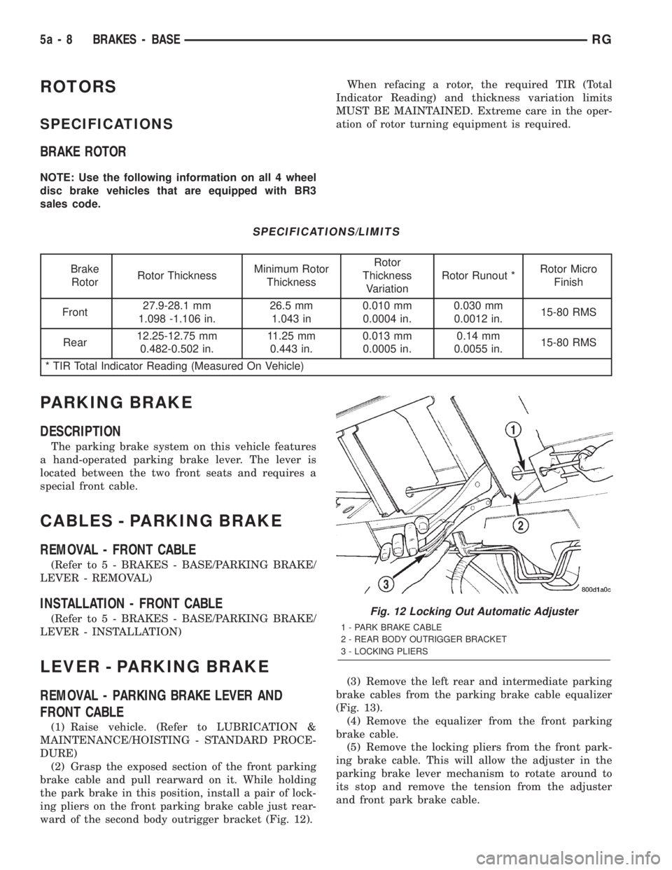
(2) Grasp the exposed section of the front parking
brake cable and pull rearward on it. While holding
the park brake in this position, install a pair of lock-
ing pliers on the front parking brake cable just rear-
ward of the second body outrigger bracket (Fig. 12).(3) Remove the left rear and intermediate parking
brake cables from the parking brake cable equalizer
(Fig. 13).
(4) Remove the equalizer from the front parking
brake cable.
(5) Remove the locking pliers from the front park-
ing brake cable. This will allow the adjuster in the
parking brake lever mechanism to rotate around to
its stop and remove the tension from the adjuster
and front park brake cable.
Fig. 12 Locking Out Automatic Adjuster
1 - PARK BRAKE CABLE
2 - REAR BODY OUTRIGGER BRACKET
3 - LOCKING PLIERS
5a - 8 BRAKES - BASERG
Page 1903 of 4284
HEATED SEAT SYSTEM
TABLE OF CONTENTS
page page
HEATED SEAT SYSTEM
DESCRIPTION............................7
OPERATION.............................8
DRIVER HEATED SEAT SWITCH
DESCRIPTION............................8
OPERATION.............................9
DIAGNOSIS AND TESTING..................9
HEATED SEAT SWITCH...................9
REMOVAL..............................10
INSTALLATION...........................10
HEATED SEAT ELEMENT
DESCRIPTION...........................10
OPERATION.............................11DIAGNOSIS AND TESTING.................11
HEATED SEAT ELEMENT.................11
HEATED SEAT SENSOR
DESCRIPTION...........................11
DIAGNOSIS AND TESTING.................11
HEATED SEAT SENSOR..................11
PASSENGER HEATED SEAT SWITCH
DESCRIPTION...........................11
OPERATION.............................11
DIAGNOSIS AND TESTING.................12
HEATED SEAT SWITCH..................12
REMOVAL..............................13
INSTALLATION...........................13
HEATED SEAT SYSTEM
DESCRIPTION
Individually controlled driver and passenger side
electrically heated front seats are available factory-
installed optional equipment on this model, when it
is also equipped with the power seat option. The
heated seat system allows both the driver and the
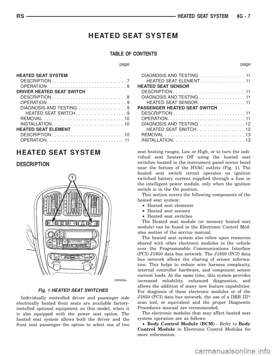
front seat passenger the option to select one of twoseat heating ranges, Low or High, or to turn the indi-
vidual seat heaters Off using the heated seat
switches located in the instrument panel center bezel
near the bottom of the HVAC outlets (Fig. 1). The
heated seat switch circuit operates on ignition
switched battery current supplied through a fuse in
the intelligent power module, only when the ignition
switch is in the On position.
This section covers the following components of the
heated seat system:
²Heated seat elements
²Heated seat sensors
²Heated seat switches
The Heated seat module (or memory heated seat
module) can be found in the Electronic Control Mod-
ules section of the service manual.
The heated seat system also relies upon resources
shared with other electronic modules in the vehicle
over the Programmable Communications Interface
(PCI) J1850 data bus network. The J1850 (PCI) data
bus network allows the sharing of sensor informa-
tion. This helps to reduce wire harness complexity,
internal controller hardware, and component sensor
current loads. At the same time, this system provides
increased reliability, enhanced diagnostics, and
allows the addition of many new feature capabilities.
For diagnosis of these electronic modules or of the
J1850 (PCI) data bus network, the use of a DRB IIIt
scan tool, or equivalent and the proper Diagnostic
Procedures manual are recommended.
The electronic modules that may affect heated seat
system operation are as follows:
²Body Control Module (BCM)- Refer toBody
Control Modulein Electronic Control Modules for
more information.
Fig. 1 HEATED SEAT SWITCHES
RSHEATED SEAT SYSTEM8G-7
Page 1981 of 4284
POWER SYSTEMS
TABLE OF CONTENTS
page page
POWER LIFTGATE SYSTEM.................. 1
POWER SLIDING DOOR SYSTEM............ 19
POWER LOCKS........................... 39POWER MIRRORS........................ 45
POWER SEATS........................... 49
POWER WINDOWS........................ 60
POWER LIFTGATE SYSTEM
TABLE OF CONTENTS
page page
POWER LIFTGATE SYSTEM
DESCRIPTION............................2
OPERATION.............................3
DIAGNOSIS AND TESTING..................4
DIAGNOSIS AND TESTING - POWER
LIFTGATE SYSTEM......................4
STANDARD PROCEDURE...................9
LIFTGATE ADJUSTMENT..................9
POWER LIFTGATE LEARN CYCLE..........9
PINCH SENSOR
DESCRIPTION............................9
OPERATION.............................9
REMOVAL...............................9
INSTALLATION...........................10
FULL OPEN SWITCH
DESCRIPTION...........................10
OPERATION.............................10
REMOVAL..............................10
INSTALLATION...........................10
LIFTGATE MOTOR
DESCRIPTION...........................11
OPERATION.............................11
REMOVAL..............................11
INSTALLATION...........................11
ENGAGE ACTUATOR
DESCRIPTION...........................12
OPERATION.............................12
REMOVAL..............................12
INSTALLATION...........................12TRANSVERSE BRACKET
DESCRIPTION...........................13
OPERATION.............................13
REMOVAL..............................13
INSTALLATION...........................13
LIFT GEAR & LINK ROD
DESCRIPTION...........................14
OPERATION.............................14
REMOVAL..............................14
INSTALLATION...........................14
LATCH
DESCRIPTION...........................15
OPERATION.............................15
REMOVAL..............................15
INSTALLATION...........................15
LATCH ACTUATOR
DESCRIPTION...........................16
OPERATION.............................16
REMOVAL..............................16
INSTALLATION...........................16
EXTERIOR HANDLE SWITCH
DESCRIPTION...........................17
OPERATION.............................17
REMOVAL..............................17
INSTALLATION...........................17
CHIME/THERMISTOR
DESCRIPTION...........................18
OPERATION.............................18
REMOVAL..............................18
INSTALLATION...........................18
RSPOWER SYSTEMS8N-1
Page 2018 of 4284
INSTALLATION
(1) Position the flex drive assembly in the vehicle.
(2) Install the flex drive on the lower drive unit.
Push straight on until it snaps in place. It may be
necessary to rotate drive unit gear slightly until the
flex drive seats in place.
(3) Install the lower drive unit cover and retaining
screws.
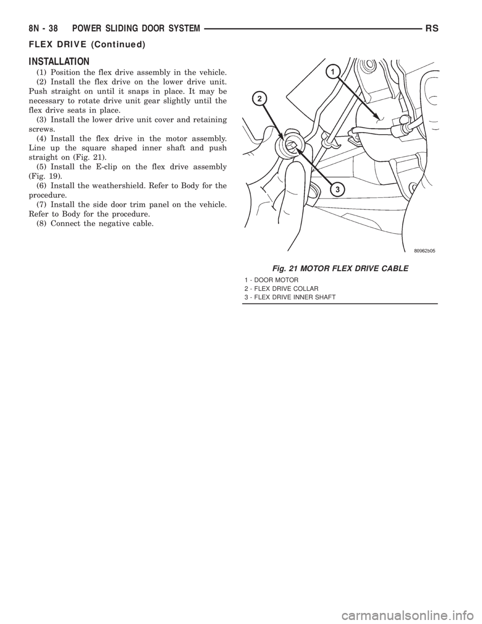
(4) Install the flex drive in the motor assembly.
Line up the square shaped inner shaft and push
straight on (Fig. 21).
(5) Install the E-clip on the flex drive assembly
(Fig. 19).
(6) Install the weathershield. Refer to Body for the
procedure.
(7) Install the side door trim panel on the vehicle.
Refer to Body for the procedure.
(8) Connect the negative cable.
Fig. 21 MOTOR FLEX DRIVE CABLE
1 - DOOR MOTOR
2 - FLEX DRIVE COLLAR
3 - FLEX DRIVE INNER SHAFT
8N - 38 POWER SLIDING DOOR SYSTEMRS
FLEX DRIVE (Continued)