2001 CHRYSLER VOYAGER magnetic
[x] Cancel search: magneticPage 52 of 4284
contains a potentiometer to monitor the seat posi-
tion. To monitor the position of the motor, the
MSMM sends out a 5-volt reference on the sensor
supply circuit. The sensor is grounded back to the
module on a common ground circuit. Based on the
position of the sensor, the MSMM monitors the
voltage change through the sensor on a separate
signal circuit.
The MSMM stores the input value of each of the
four seat potentiometers in memory when the sys-
tem requests a set. The driver can initiate a mem-
ory recall, using either the door mounted memory
switch or the RKE transmitter (if the remote linked
to memory feature is enabled via the EVIC). When
initiated, the MSMM adjusts the four seat sensors
(by using the motors) to match the memorized seat
position data.
For safety, the memory seat recall is disabled by
the MSMM when the vehicle is out of park position
or if the speed is not zero. Any obstruction to seat
movement over a 2-second delay will cause the seat
to stop moving in which case a stalled motor would
be detected by the MSMM and the corresponding
seat output would be deactivated. However, if the
object obstructing the seat is removed, the seat will
function normally again.
3.13.2 MEMORY MIRRORS
Each outside mirror contains vertical and hori-
zontal bi-directional drive positioning motors and
position sensors. The MSMM provides a 5-volt
reference on the signal circuit to each position
sensor. The sensors share a common ground circuit.
The MSMM monitors the position of the mirror
motors by measuring the voltage on each signal
circuit. When a memory position is set, the MSMM
monitors and stores the position of the outside
mirrors. The MSMM adjusts the mirrors to the
appropriate positions when a memory recall mes-
sage is received from the RKE or is requested from
the memory set switch.
The power mirror switch during non-memory
operation operates both mirrors independently of
the MSMM.
3.14 OVERHEAD CONSOLE
3.14.1 COMPASS/MINI-TRIP COMPUTER
(CMTC)
The compass/mini-trip computer is located in the
overhead console. It displays to the driver the
direction the vehicle is traveling and the current
outside temperature, as well as the following trav-
eler navigational information: average fuel econ-
omy (AVG ECO), distance to empty (DTE), instan-
taneous fuel economy (ECO), elapsed time (ET),and trip odometer (ODO). The information needed
for the CMTC functions is received over the PCI bus
from other modules.
3.14.2 ELECTRONIC VEHICLE
INFORMATION CENTER (EVIC)
The Electronic Vehicle Information Center
(EVIC) includes all the same functions and is lo-
cated in the same area as the Compass/Mini-Trip
Computer, but it adds a number of warning mes-
sages. Also, the EVIC messages are spelled out on
the screen, for example, DISTANCE TO EMPTY,
where the Mini-Trip Computer displays only shows
DTE.
If the compass/mini-trip computer or EVIC has
been replaced, it may be necessary to reset the
calibration.
3.14.3 SETTING THE COMPASS
The compass/mini-trip computer and EVIC are
self-calibrated and requires no adjustment. The
word CAL will be displayed to indicate that the
compass is in the fast calibrating mode. CAL will
turn off after the vehicle has gone in three complete
circles without stopping, in an area free of magnetic
disturbance.
If the module displays the temperature while the
compass is blank or shows a false reading, the
vehicle must be demagnetized. See the service man-
ual for the proper procedure.
If the compass still goes blank after the vehicle is
demagnetized, the compass/mini-trip/EVIC module
must be replaced.
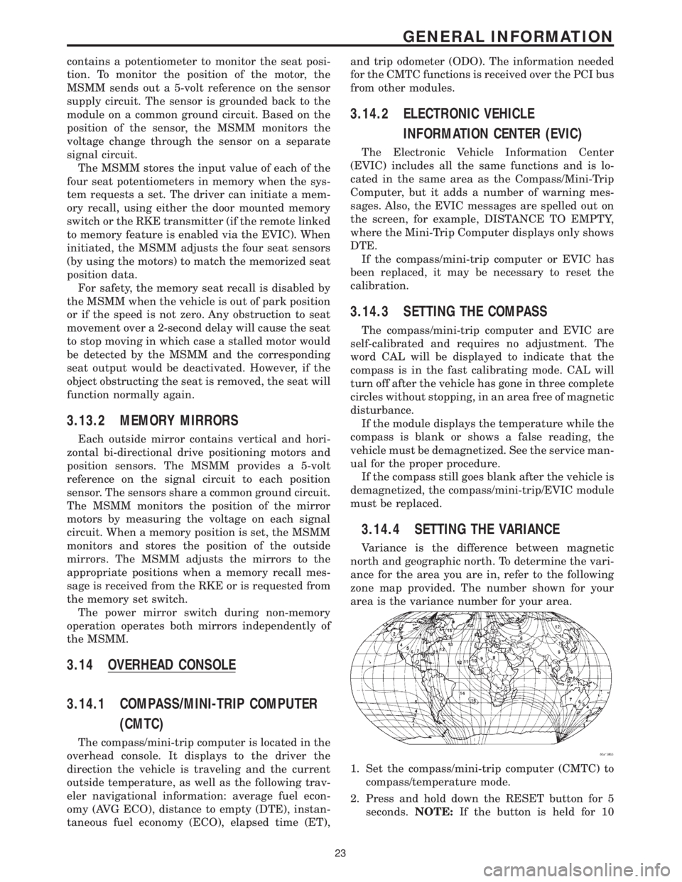
3.14.4 SETTING THE VARIANCE
Variance is the difference between magnetic
north and geographic north. To determine the vari-
ance for the area you are in, refer to the following
zone map provided. The number shown for your
area is the variance number for your area.
1. Set the compass/mini-trip computer (CMTC) to
compass/temperature mode.
2. Press and hold down the RESET button for 5
seconds.NOTE:If the button is held for 10
23
GENERAL INFORMATION
Page 53 of 4284

seconds instead of 5, the CMTC will set the
variance to 8 and enter the fast calibration
mode.
3. The VAR light will come on and the last variance
setting will be displayed.
4. Press the STEP button to set the zone number.
5. Press the US/M button and resume normal op-
eration.
NOTE: Do not attach any magnetic device
such as a magnetic CB antenna to the
vehicle. This can cause the compass to give
false readings.
3.15 POWER DOOR LOCK SYSTEM
When the BCM receives input for a lock request
from a door lock switch, RKE or cylinder lock switch
(only with VTSS), it will turn the lock driver on for
a specified time of 375 msec. If the request is there
beyond 375 msec, the BCM considers the door lock
signal stuck. Once a door lock or unlock signal is
stuck for longer than 10 seconds, the BCM will set
a trouble code and the signal input is ignored until
the stuck condition disappears. The door lock
switches provide a variable amount of resistance
thereby dropping the voltage of the multiplexed
(MUX) circuit and the BCM will respond to that
command.
3.15.1 SLIDING DOOR MEMORY LOCK
When the BCM receives an input for a lock
request and a sliding door is open, the BCM will
turn on the lock driver as described above, and will
turn it on again when all sliding doors are closed.
NOTE: If the BCM receives an unlock input before
a sliding door is closed, this will cancel the memory
lock.
3.15.2 DOOR LOCK INHIBIT
When the key is in the ignition and in any
position and either front door is open, the door lock
switches LOCK functions are disabled. The UN-
LOCK functions are still functional. This protects
against locking the vehicle with the keys still in the
ignition. The RKE key fob will still lock the doors as
usual. This allows the driver to lock the vehicle with
the engine running for warm up.
3.15.3 AUTOMATIC DOOR LOCKS
This feature can be enabled or disabled by using
either the DRBIIItor the customer programming
method. When enabled all the doors will lock when
the vehicle reaches a speed of 18 MPH (29 KMH)
and all the doors are closed. If a door is opened and
the vehicle slows to below 18 MPH (29 KMH), thedoor locks will operate again once all doors are
closed and the speed is above 15 MPH (24 KMH).
3.15.4 REMOTE KEYLESS ENTRY (RKE)
The body control module interfaces with the RKE
module via a one-way serial bus interface. The RKE
module is not on the PCI bus. The RKE module
sends a 0-5 volt pulse width signal to the BCM
depending on which button on the transmitter was
pressed. The BCM controls the door lock/unlock
functions and the arming/disarming of the Vehicle
Theft Security System (if equipped) and the activa-
tion of illuminated entry. The BCM will also send
the appropriate messages to the Power Sliding
Doors and Power Liftgate modules. The Intelligent
Power Module (IPM) activates the park lamps,
headlamps, and horn for horn chirp when sent the
appropriate message from the BCM as received
from the RKE transmitter. When a one-button
press is made for unlock, both driver side doors will
unlock and the front and rear turn signal will flash.
When a second press is initiated (within 5 seconds
of the first) both passenger doors will unlock and all
four turn signals will flash.
The RKE module is capable of retaining up to 4
individual access codes (4 transmitters). If the
PRNDL is in any position except park, the BCM will
ground the interface thereby disabling the RKE.
The 2 button transmitter will have 2-CR2016
batteries in series. The 5 button transmitter will
have 1-CR2016 battery. The minimum battery life
should be approximately 4.7 years based on 20
transmissions a day at 84ÉF (25ÉC). Using the
DRBIIItand selecting RKE FOB Test can test the
transmitter.
The RKE module can be programmed via the
DRBIIItor the customer programming method.
The BCM will only allow programming mode to be
entered when the ignition is in the on position, the
PRNDL is in park position, and the VTSS (if
equipped) is in the disarmed mode.
3.16 POWER FOLDING MIRRORS
The power folding mirrors are powered to two
positions: folded and unfolded. The driver may
choose fold or unfold with a switch that is located on
the right side of the steering column. The folding
mirror switch grounds a sense wire that comes from
the Body Control Module when it is placed in the
fold position. The mirrors will move to the position
designated by the switch whether the ignition
switch is the On or Off position and both front doors
are closed. When the Power Folding Mirror switch
is left in the fold position during a vehicle exit the
mirrors will automatically unfold then refold after
both front doors are closed. This is to prevent mirror
contact with either front door when opened. When
24
GENERAL INFORMATION
Page 1164 of 4284
6.0 GLOSSARY OF TERMS
ABSantilock brake system
CABcontroller antilock brake
CCDChrysler Collision Detection
DLCdata link connector
DRBdiagnostic read-out box
EDWelectrical distribution wiring
EMIelectro magnetic interference
HCUhydraulic control unit
ICUintegrated control unit
IFLinlet front leftIFRinlet front right
IRLinlet rear left
IRRinlet rear right
JBLKjunction block
OFLoutlet front left
OFRoutlet front right
ORLoutlet rear left
ORRoutlet rear right
PDCpower distribution center
P/Mpump motor
RFIradio frequency interference
WSSwheel speed sensor
7
GENERAL INFORMATION
Page 1222 of 4284
sponder ID message to the SKIM. The SKIM com-
pares the transponder ID message to the available
valid key codes in SKIM memory (8 key maximum
at any one time). After validating the ignition key,
the SKIM sends a PCI Bus message called a seed
request to the ECM, then waits for the ECM re-
sponse. If the ECM does not respond, the SKIM will
send the seed request again. After three failed
attempts, the SKIM will stop sending the seed
request and store a trouble code in memory. If the
ECM sends a seed response, the SKIM sends a
valid/invalid key message to the ECM. This is an
encrypted message that is generated using the
following:
VIN - Vehicle Identification Number.
Seed - This is a random number that is generated
by the ECM at each ignition key cycle.
The VIN and seed are two variables used in the
rolling code algorithm that encrypts the valid/
invalid key message. The ECM uses the rolling code
algorithm to receive, decode and respond to the
valid/invalid key message sent by the SKIM. After
sending the valid/invalid key message, the SKIM
waits 3.5 seconds for an ECM status message from
the ECM. If the ECM does not respond with a valid
key message to the SKIM, a fault is detected and a
code is stored.
The SKIS incorporates a warning lamp located in
the information center. The lamp receives switched
ignition voltage and is hardwired to the body con-
trol module. The lamp is actuated when the SKIM
sends a PCI Bus message to the body control
module requesting the lamp on. The body control
module then provides the ground for the lamp.
The SKIM will request lamp operation for the
following:
± bulb check at ignition on
± to alert the vehicle operator to a SKIS malfunc-
tion
± when the SKIM is in customer key programming
mode
For all faults except transponder faults the lamp
remains on steady. In the event of a transponder
fault the lamp will flash at a rate of 1Hz (once per
second). If a fault is present, the lamp will remain
on or flashing for the complete ignition cycle. If a
fault is stored in SKIM memory which prevents the
system from operating properly, the ECM will allow
the engine to start and idle for 2 seconds then stall.
This may occur up to six times. After the sixth
attempt, the ECM disables the starter relay until
the fault is corrected.
3.3 DIAGNOSTIC TROUBLE CODES
Each diagnostic trouble code (DTC) is diagnosed
by following a specific procedure. The diagnostic
test procedure contains step-by-step instruction fordetermining the cause of the DTC as well as no
trouble code problems. It is not necessary to per-
form all of the tests in this book to diagnose an
individual code.
Always begin diagnosis by reading the DTC's
using the DRBIIIt.
3.3.1 HARD CODE
A DTC that comes back within one cycle of the
ignition key is a hard code. This means that the
problem is current every time the ECM/SKIM
checks that circuit or function. Procedures in this
manual verify if the DTC is a hard code at the
beginning of each test. When the fault is not a hard
code, an intermittent test must be performed.
NOTE: If the DRBIIItdisplays faults for multiple
components (i.e. ECT, VSS, Oil Temp sensors) iden-
tify and check the shared circuits for possible prob-
lems before continuing (i.e. sensor grounds or 5-volt
supply circuits). Refer to the appropriate schematic
to identify shared circuits.
3.3.2 INTERMITTENT CODE
A DTC that is not current every time the ECM/
SKIM checks the circuit or function is an intermit-
tent code. Most intermittent DTCs are caused by
wiring or connector problems. Problems that come
and go like this are the most difficult to diagnose;
they must be looked for under specific conditions
that cause them. The following checks may assist
you in identifying a possible intermittent problem.
²Visually inspect the related wire harness connec-
tors. Look for broken, bent, pushed out, or cor-
roded terminals.
²Visually inspect the related wire harness. Look
for chafed, pierced, or partially broken wire.
²Refer to hotlines or technical service bulletins
that may apply.
NOTE: Electromagnetic (radio) interference can
cause an intermittent system malfunction. This
interference can interrupt communication between
the ignition key transponder and the SKIM.
3.3.3 ECM DIAGNOSTIC TROUBLE CODES
IMPORTANT NOTE:Before replacing the ECM
for a failed driver, control circuit or ground circuit,
be sure to check the related component/circuit in-
tegrity for failures not detected due to a double fault
in the circuit. Most ECM driver/control circuit fail-
ures are caused by internal failures to components
(i.e. relays and solenoids) and shorted circuits (i.e.
sensor pull-ups, drivers and ground circuits). These
faults are difficult to detect when a double fault has
occurred and only one DTC has set.
If the DRB displays faults for multiple compo-
nents (i.e. VSS, ECT, Batt Temp, etc.), identify and
3
GENERAL INFORMATION
Page 1818 of 4284
ANTENNA MODULE
DESCRIPTION
The antenna module is an electromagnetic circuit
component designed to capture and enhance RF
(Radio Frequency) signals in both the AM and FM
broadcast bands. The antenna module is mounted to
the right rear roof rail under the headliner. The mod-
ule is grounded through the mounting bracket and
fastener. The module has a two wire electrical con-
nector that connects to the integral radio antenna,located on the right rear quarter glass. There is also
an electrical connector for battery voltage and a coax
cable connector.OPERATION
The antenna module receives both AM and FM
radio signals supplied by the side window integral
radio antenna system and selectively amplifies them.
The amplified signal is then sent through the body
length coax cable to the radio input.
DIAGNOSIS AND TESTING - ANTENNA MODULE
CONDITION POSSIBLE CAUSES CORRECTION
NO AM RECEPTION,
WEAK FM RECEPTION1. Antenna module to antenna
connector open or disconnected.1. Repair open, reconnect
antenna module connector to
glass mounted antenna.
2. Coax open or disconnected. 2. Repair open, reconnect coax.
3. No battery power at antenna
module.3. Check fuse. if okay, repair
open in battery voltage circuit.
NO AM OR FM
RECEPTION1. Coax disconnected at radio. 1. Reconnect coax.
2. Coax shorted to ground. 2. Repair or Replace coax
WEAK OR NO AM/FM
RECEPTION1. Antenna Module faulty. 1. Substitute known good
module. If reception improves,
Antenna Module was faulty.
REMOVAL
(1) Disconnect and isolate the battery negative
cable.
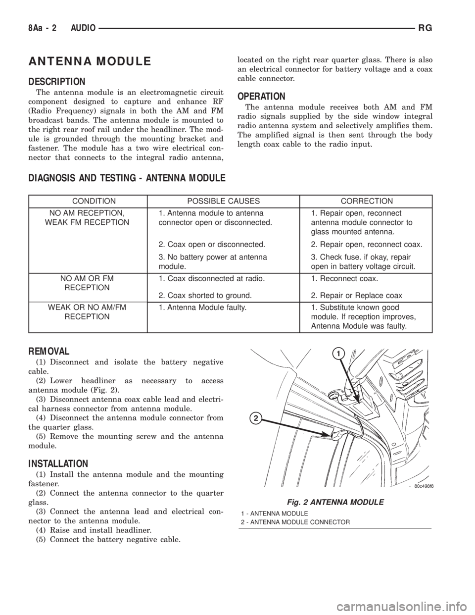
(2) Lower headliner as necessary to access
antenna module (Fig. 2).
(3) Disconnect antenna coax cable lead and electri-
cal harness connector from antenna module.
(4) Disconnect the antenna module connector from
the quarter glass.
(5) Remove the mounting screw and the antenna
module.
INSTALLATION
(1) Install the antenna module and the mounting
fastener.
(2) Connect the antenna connector to the quarter
glass.
(3) Connect the antenna lead and electrical con-
nector to the antenna module.
(4) Raise and install headliner.
(5) Connect the battery negative cable.
Fig. 2 ANTENNA MODULE
1 - ANTENNA MODULE
2 - ANTENNA MODULE CONNECTOR
8Aa - 2 AUDIORG
Page 1875 of 4284
CHARGING
TABLE OF CONTENTS
page page
CHARGING
DESCRIPTION...........................21
OPERATION.............................21
DIAGNOSIS AND TESTING.................22
ON-BOARD DIAGNOSTIC SYSTEM.........22
SPECIFICATIONS........................22
SPECIAL TOOLS.........................23
BATTERY TEMPERATURE SENSOR
DESCRIPTION...........................23
OPERATION.............................23
REMOVAL..............................23
GENERATOR
DESCRIPTION...........................23
OPERATION.............................23REMOVAL..............................23
INSTALLATION...........................24
GENERATOR DECOUPLER PULLEY
DESCRIPTION...........................25
OPERATION.............................25
DIAGNOSIS AND TESTING.................25
GENERATOR DECOUPLER...............25
REMOVAL..............................25
INSTALLATION...........................26
VOLTAGE REGULATOR
DESCRIPTION...........................26
OPERATION.............................26
REMOVAL..............................26
CHARGING
DESCRIPTION - CHARGING SYSTEM
The charging system consists of:
²Generator
²Decoupler Pulley (If equipped)
²Electronic Voltage Regulator (EVR) circuitry
within the Powertrain Control Module (PCM)
²Ignition switch (refer to the Ignition System sec-
tion for information)
²Battery (refer to the Battery section for informa-
tion)
²Battery temperature sensor
²Voltmeter (refer to the Instrument Cluster sec-
tion for information)
²Wiring harness and connections (refer to the
Wiring section for information)
²Accessory drive belt (refer to the Cooling section
for more information)
OPERATION - CHARGING SYSTEM
The charging system is turned on and off with the
ignition switch. The system is on when the engine is
running and the ASD relay is energized. When the
ASD relay is on, voltage is supplied to the ASD relay
sense circuit at the PCM. This voltage is connected
through the PCM and supplied to one of the genera-
tor field terminals (Gen. Source +) at the back of the
generator.
The generator is driven by the engine through a
serpentine belt and pulley or decoupler pulley
arrangement.The amount of DC current produced by the gener-
ator is controlled by the EVR (field control) circuitry
contained within the PCM. This circuitry is con-
nected in series with the second rotor field terminal
and ground.
A battery temperature sensor is used to sense bat-
tery temperature. This temperature data, along with
data from monitored line voltage, is used by the PCM
to vary the battery charging rate. This is done by
cycling the ground path to control the strength of the
rotor magnetic field. The PCM then compensates and
regulates generator current output accordingly to
maintain system voltage at the targeted system volt-
age based on battery temperature.
All vehicles are equipped with On-Board Diagnos-
tics (OBD). All OBD-sensed systems, including EVR
(field control) circuitry, are monitored by the PCM.
Each monitored circuit is assigned a Diagnostic Trou-
ble Code (DTC). The PCM will store a DTC in elec-
tronic memory for certain failures it detects. Refer to
On-Board Diagnostics in the Electronic Control Mod-
ules(Refer to 8 - ELECTRICAL/ELECTRONIC CON-
TROL MODULES/POWERTRAIN CONTROL
MODULE - DESCRIPTION) section for more DTC
information.
The Check Gauges Lamp (if equipped) monitors:
charging system voltage,engine coolant tempera-
ture and engine oil pressure. If an extreme condition
is indicated, the lamp will be illuminated. This is
done as reminder to check the three gauges. The sig-
nal to activate the lamp is sent via the PCI bus cir-
cuits. The lamp is located on the instrument panel.
Refer to the Instrument Cluster section for additional
information.
RSCHARGING8F-21
Page 1877 of 4284
SPECIAL TOOLS
SPECIAL TOOLS
BATTERY TEMPERATURE
SENSOR
DESCRIPTION
The PCM incorporates a Battery Temperature Sen-
sor (BTS) on its circuit board.
OPERATION
The PCM uses the temperature of the battery area
to control the charge rate. This temperature data,
along with data from monitored line voltage, is used
by the PCM to vary the battery charging rate. The
system voltage is higher at cold temperatures and is
gradually reduced as temperature around the battery
increases.
The function of the battery temperature sensor
(BTS) is to enable control of the generator output
based upon ambient battery temperature. As battery
temperature increases, the charging rate should
decrease. As battery temperature decreases, the
charging rate should increase. The sensor functions
similar to the ECT sensor with one major difference,
the ambient sensor does not have a dual temperature
range program. The PCM maintains the optimal out-
put of the generator by monitoring battery voltage
and controlling battery voltage to a range of
13.5-14.7 volts based on battery temperature.
The battery temperature sensor is also used for
OBD II diagnostics. Certain faults and OBD II mon-
itors are either enabled or disabled depending upon
the battery temperature sensor input (example: dis-
able purge and EGR, enable LDP). Most OBD II
monitors are disabled below 20ÉF.
REMOVAL
The battery temperature sensor is not a serviced
separately. If replacement is necessary, the PCM
must be replaced.
GENERATOR
DESCRIPTION
The generator is belt-driven by the engine. It is
serviced only as a complete assembly. The generator
produces DC voltage at the B+ terminal. If the gen-
erator is failed, the generator assembly subcompo-
nents (generator and decoupler pulley) must be
inspected for individual failure and replaced accord-
ingly.
OPERATION
As the energized rotor begins to rotate within the
generator, the spinning magnetic field induces a cur-
rent into the windings of the stator coil. Once the
generator begins producing sufficient current, it also
provides the current needed to energize the rotor.
The Y type stator winding connections deliver the
induced AC current to 3 positive and 3 negative
diodes for rectification. From the diodes, rectified DC
current is delivered to the vehicles electrical system
through the generator, battery, and ground terminals.
Noise emitting from the generator may be caused
by:
²Worn, loose or defective bearings
²Loose or defective drive pulley (2.4L) or decou-
pler (3.3/3.8L)
²Incorrect, worn, damaged or misadjusted drive
belt
²Loose mounting bolts
²Misaligned drive pulley
²Defective stator or diode
²Damaged internal fins
REMOVAL - 2.4L
(1) Release hood latch and open hood.
(2) Disconnect battery negative cable.
(3) Disconnect the Inlet Air Temperature sensor.
(4) Remove the Air Box, refer to the Engine/Air
Cleaner for more information.
(5) Remove the EVAP Purge solenoid from its
bracket and reposition.
(6) Disconnect the push-in field wire connector
from back of generator.
(7) Remove nut holding B+ wire terminal to back
of generator.
(8) Separate B+ terminal from generator.
(9) Remove accessory drive belt, refer to the Cool-
ing System section for proper procedures.
(10) Remove the generator.
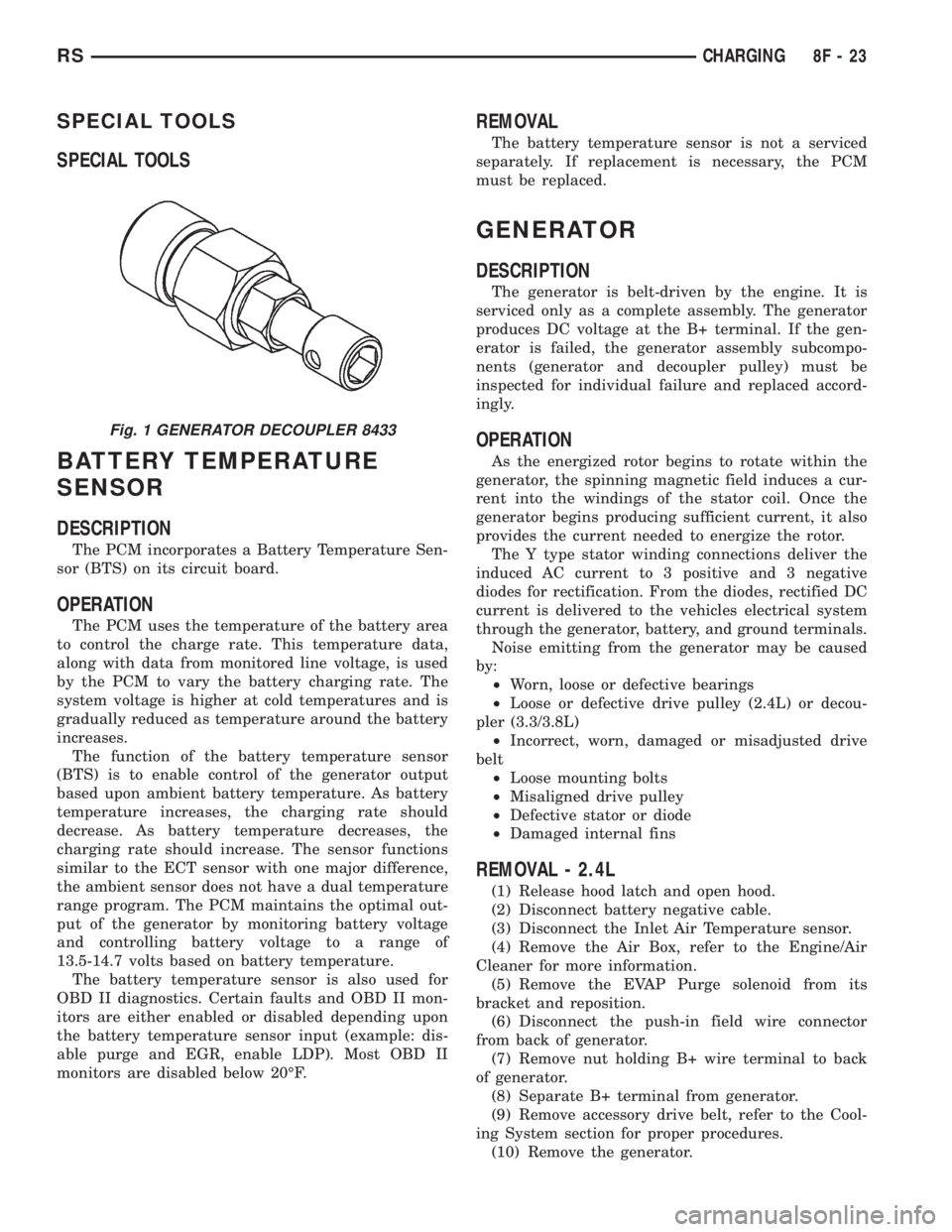
Fig. 1 GENERATOR DECOUPLER 8433
RSCHARGING8F-23
Page 1880 of 4284
INSTALLATION
(1) Install the Generator Decoupler to the genera-
tor shaft.
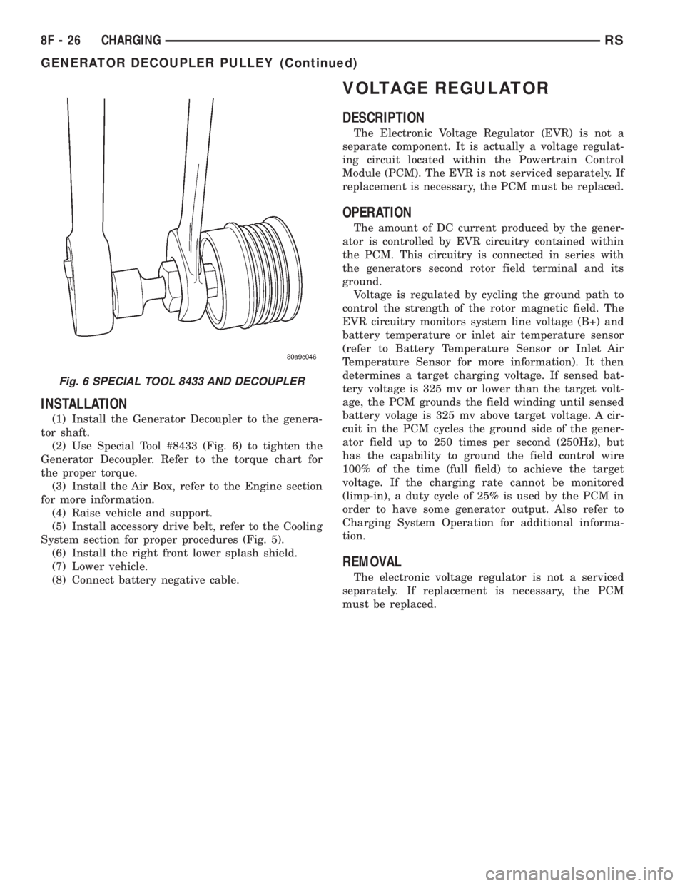
(2) Use Special Tool #8433 (Fig. 6) to tighten the
Generator Decoupler. Refer to the torque chart for
the proper torque.
(3) Install the Air Box, refer to the Engine section
for more information.
(4) Raise vehicle and support.
(5) Install accessory drive belt, refer to the Cooling
System section for proper procedures (Fig. 5).
(6) Install the right front lower splash shield.
(7) Lower vehicle.
(8) Connect battery negative cable.
VOLTAGE REGULATOR
DESCRIPTION
The Electronic Voltage Regulator (EVR) is not a
separate component. It is actually a voltage regulat-
ing circuit located within the Powertrain Control
Module (PCM). The EVR is not serviced separately. If
replacement is necessary, the PCM must be replaced.
OPERATION
The amount of DC current produced by the gener-
ator is controlled by EVR circuitry contained within
the PCM. This circuitry is connected in series with
the generators second rotor field terminal and its
ground.
Voltage is regulated by cycling the ground path to
control the strength of the rotor magnetic field. The
EVR circuitry monitors system line voltage (B+) and
battery temperature or inlet air temperature sensor
(refer to Battery Temperature Sensor or Inlet Air
Temperature Sensor for more information). It then
determines a target charging voltage. If sensed bat-
tery voltage is 325 mv or lower than the target volt-
age, the PCM grounds the field winding until sensed
battery volage is 325 mv above target voltage. A cir-
cuit in the PCM cycles the ground side of the gener-
ator field up to 250 times per second (250Hz), but
has the capability to ground the field control wire
100% of the time (full field) to achieve the target
voltage. If the charging rate cannot be monitored
(limp-in), a duty cycle of 25% is used by the PCM in
order to have some generator output. Also refer to
Charging System Operation for additional informa-
tion.
REMOVAL
The electronic voltage regulator is not a serviced
separately. If replacement is necessary, the PCM
must be replaced.
Fig. 6 SPECIAL TOOL 8433 AND DECOUPLER
8F - 26 CHARGINGRS
GENERATOR DECOUPLER PULLEY (Continued)