2001 CHRYSLER VOYAGER engine oil
[x] Cancel search: engine oilPage 38 of 4284
This feature dims the interior lighting (courtesy
lamps) gradually if the BCM does not receive any
new inputs that would cause the interior lamps to
remain on.
²PWM Instrument Panel Dimming
²Door Lock Inhibit
This feature disables the door lock functions if the
key is in the ignition and either front door is ajar.
Pressing the RKE lock/unlock button under these
conditions, result in normal lock/unlock activation.
²Power Sliding Door Switch Inputs
The BCM has 4 switch inputs for the power
sliding door feature: Located in the overhead con-
sole are the Left and Right side sliding door
switches to activate either or both sliding doors
under the proper conditions. Also are B-Pillar
switches located on the Left and Right B-pillar
posts.
²Power Liftgate Switch Input
The BCM has 1 Liftgate switch input located in
the overhead console
²Power Lockout Switch Input
The BCM has 1 Lockout switch that when en-
abled will disable the B-Pillar sliding door switches
from activating either sliding door when depressed.
When replacing a body control module there are 2
modules available, a Base and a Midline. The
Midline controller is used on vehicles that have
Power Door Locks. If a vehicle is equipped with the
Vehicle Theft Security System, the midline control-
ler becomes a premium when the theft feature is
enabled.
NOTE: DO NOT SWAP THE BODY CONTROL
MODULE BETWEEN VEHICLES OR BODY
CONTROL MODULES OFF THE SHELF.
Engineering does not recommend that service,
dealers or the plant swap Body Control Modules
(BCM) between vehicles or off the shelf. The BCM
has internal diagnostic capability that assists in
diagnosing the system. When an ªOpenº or a
ªShortº circuit exists, the diagnostic tool can be
used to read the BCM codes. The codes are very
descriptive in identifying the appropriate feature
that has faulted.
3.4 CHIME WARNING SYSTEM
The BCM monitors the door/liftgate ajar
switches, multifunction switches, headlight switch,
ignition switch, PCI bus, and the diagnostic tool to
perform various chime operations. The BCM uses a
low-side driver to control the chime located in the
cluster.
The chime system provides the Driver with warn-
ing chimes for:
²Seat belt
²Exterior lights on
²Key-in Ignition
²Key-in Accessory
²Engine temperature critical
²Low washer fluid
²Turn signals on
²Dome light on
²Low oil pressure
²Any warning lamp announcement
²High-speed warning Gulf Coast Countries (GCC)
only
The output sound intensity of the chime is ap-
proximately 72 decibels.
3.4.1 CHIME PRIORITY
The following list indicates the priority of the
chime when more than one chime is active at the
same time:
²Seat belt warning
²High-speed warning Gulf Coast Countries (GCC)
only
²Turn signal on
²Chime request
²Warning lamp announcement
The cluster is responsible to set priority on all
warning lamp announcement chimes.
3.4.2 CHIME ON CONDITIONS
The following is a list of the chime warnings and
when they will sound.
Driver 's Seat
belt Unbuckled:Sounds for approximately 662
seconds when the igntion is turned
on and driver 's seat belt is not
buckled, as a reminder to the
driver to buckle the seat belt.
Exterior Lights
On:Ignition is in the lock position,
the driver door is ajar, and the
headlight switch is left in any
position, other than auto or off.
The chime will sound as a warn-
ing to the driver until one of the
above conditions is removed or
until the battery protection time
of 3 minutes has expired.
Key-In Ignition: Ignition is in the lock position,
driver door is ajar and the key is
in the ignition. The chime will
sound until one of the above con-
ditions is removed or until the
battery protection time of 15 min-
utes has expired.
9
GENERAL INFORMATION
Page 39 of 4284
Turn Signal On: When the BCM detects a turn
signal input continuously for
1.0mile/0.6km and the vehicle
speed is greater than 15 mph/
24kph, the chime will sound until
the specific turn signal is can-
celled.
Dome Lights On: Ignition is in the lock position,
driver door ajar, and the dome
light switch is left in the on
position. The chime will sound
until one of the above conditions
is removed or until the battery
protection time of 15 minutes has
expired.
Low Oil Pres-
sure:The chime will sound when the
engine is operating and the oil
pressure drops below 4psi/27.5kPa.
Engine
Temperature
Critical:The chime will sound when the
engine is operating and the cool-
ant temperature exceeds 252ÉF/
122Cor 234É/112C(diesel).The
chime is continuous at 257ÉF/
125C and will chime for 4 min-
utes and stop if the temperature
drops below 255ÉF/123C.
Low Washer
FluidThe chime will sound when the
washer fluid drops below a spe-
cific level.
Warning Lamp
Announcement:A chime will sound to alert the
driver to scan the instrument
panel to see which warning lamp
is illuminated. The door/liftgate
ajar warning lamp will appear
without a chime if the vehicle is
running and a door or the liftgate
is opened. A chime will sound if
the door or liftgate is still open
and the vehicle speed is greater
than 4mph/6kph.
High-speed
warning Gulf
Coast Countries
(GCC) onlyThe chime will sound, acting as a
warning to the driver that the
vehicle speed has exceed
75mph62/120kph63.3.4.3 WARNING LAMP ANNOUNCEMENT
Low Fuel Lamp: The cluster will request a single
chime after the indicator is illu-
minated.
Volt Lamp: The cluster will request a single
chime after the indicator is illu-
minated.
Oil Pressure
Lamp:The cluster will request a single
chime after illuminating the in-
dicator above 450rpm vehicle op-
eration.
Headlight Out
Lamp:The cluster will request a single
chime after the indicator is illu-
minated.
Liftgate Ajar
Lamp:The BCM determines when to
chime for liftgate ajar.
Fasten Seat Belt
Lamp:The BCM will request five chimes
from the MIC when the ignition
is turned to the unlock/run/start
positions if the driver seat belt is
not buckled.
Check Engine
Lamp:The cluster will request a single
chime after the indicator is illu-
minated.
Low Washer
Fluid Lamp:The cluster will request a single
chime after the indicator is illu-
minated.
Engine Tempera-
ture Lamp:The cluster will request a single
chime when the indicator is first
illuminated at 252ÉF/122C.
3.4.4 OTHER CHIME ON CONDITIONS
Bulb Check: The chime will sound three times
during bulb check.
Programming of
an Additional
Key Fob:A double cluster chime will sound,
which signals that the program
mode has been initiated.
Programming for
Rolling Door
Locks:When the programming has been
completed, a single tone from the
chime system, will occur.
10
GENERAL INFORMATION
Page 45 of 4284
the CPA is not properly engaged, a voltage on pin 38
will be interpreted as an unseated connector and a
fault will set.
Flash programming voltage Ð20 volt input on
pin 42. When a DRBIIItis connected and the
proper flash reprogramming sequence is selected,
the 20 volt signal will be applied through pin 42.
3.9 HEATING & A/C
3.9.1 AUTOMATIC TEMPERATURE
CONTROL (ATC)
3.9.1.1 CABIN HEATER
For vehicles equipped with a diesel engine, a
Cabin Heater is used in conjunction with the HVAC
system. The Cabin Heater is designed to supply the
vehicle's occupants with heat prior to the engine
reaching operating temperature. For additional in-
formation on this system, refer to Cabin Heater
under General Information and Diagnostic Proce-
dures in this manual.
3.9.1.2 SYSTEM OPERATION
The Automatic Temperature Control (ATC) sys-
tem provides fully adjustable three zone climate
control; Driver front zone, Passenger Front zone
and Rear zone. The following is a list of ATC
controls and features:
± a POWER button which allows the operator to
turn the system completely off.
± AUTO HIGH/LOW switch allows the operator
to select what rate (fan speed) the system will
provide the selected comfort level.
± DRIVER, REAR and PASSENGER rocker
switches to select desired temperature for each
zone.
± Recirculation button allows cooling air to be
recirculated which maximizes cooling ability.
± A/C select button allows the operator to turn
the A/C compressor off.
± Defroster button allows the operator to turn on
the defroster independently during automatic
control.
± Fan control rotary switch for selecting fan
speed.
± Mode rotary switch for selecting heating/
cooling direction.
± REAR SYSTEM rotary switch for activating
the Rear ATC Switch allowing intermediate
passenger control over rear climate control.
3.9.1.3 BLOWER MOTOR OPERATION
The Automatic Temperature Control (ATC) front
and rear blower control provides continuously vari-
able control of air flow rate to meet occupant
comfort requirements. Pulse width modulation of
the blower motor power allows the front and rear
blower to operate at any speed from off to full speed.
When front or rear blower operation is required, the
ATC sends a PCI Bus message to the Front Control
Module (FCM) requesting blower relay ON. The
FCM provides a ground for the front and rear
blower motor relay coils, activating both relays. The
front and rear blower relays provide 12 volts to
their respective blower motor power modules. Each
module provides a 12 volt blower motor control
signal to the ATC. The ATC provides a pulse width
modulated (duty-cycle) ground signal to this circuit
based on climate requirements. The higher voltage
on the signal circuit (less duty-cycle ground) the
lower the blower speed request. The lower voltage
on the signal circuit (more duty-cycle ground) the
higher the blower speed request.
3.9.1.4 INFRARED SENSORS
The ATC system uses infrared (I/R) sensors to
monitor and control oocupant comfort levels. This
sensing system replaces interior air temperature
and solar sensors which required complex control
programs to maintain occupant comfort levels. The
front I/R sensor is located in the instrument panel
center bezel outlet. The rear I/R sensor is located in
the rear overhead mounted ATC switch.
3.9.1.5 REAR ATC SWITCH
The rear ATC switch is mounted in the headliner.
The switch contains a rotary adjustment for fan
speed, a rotary adjustment for mode selection, a
push button switch for temperature selection and a
digital display of the selected temperature.
3.9.1.6 COOLDOWN TESTING
The ATC provides a feature referred to as a
Cooldown Test. This test is initiated using the
DRBIIItand is designed to check the performance
of the air conditioning system. The ATC will not
perform this test if the ambient air temperature is
below 12ÉC (53ÉF). During the test, the ATC com-
pares the ambient air temperature to the evapora-
tor temperature sensor. To pass the cooldown test,
the evap temperature sensor must drop -6ÉC (20ÉF)
below ambient temperature within 2 minutes of
start of test. At the completion of the cooldown test
the DRBIIItwill display one of the following mes-
sages indicating test outcome:
± Cooldown Test Passed
± Cooldown Test Failed
16
GENERAL INFORMATION
Page 51 of 4284

On vehicles equipped with AutoStick, the display
includes an O/D OFF indicator that is illuminated
when the driver presses the Overdrive Off button
on the transaxle shifter.
3.11.1 INSTRUMENT CLUSTER SELF TEST
1. Depress and hold the Odometer Reset button.
2. Turn the ignition switch to the RUN/START
position.
3. Release the Odometer reset button.
The Instrument Cluster will illuminate all indi-
cators and step the gauges through several calibra-
tion points. Also, the odometer will display any
stored codes that may have set.
3.11.2 MESSAGE CENTER
The Message Center is located above the brow of
the Instrument Cluster. It houses the following
warning indicators: Check Engine/Service Engine
Soon, high beam, left and right turn signals, Secu-
rity Alarm Set, and low oil pressure. On base
models equipped with the three-speed transaxle,
these indicators appear in the face of the cluster.
The Security Alarm set indicator is a red circle.
Activation of Instrument Cluster indicators is
coordinated with indicators in the message center
and EVIC to avoid redundancy. A revised safety
standard now requires that the seat belt warning
lamp in the Instrument Cluster remain lit if the
driver seat belt is not buckled. A headlamp out ISO
indicator has been added to the Instrument Cluster
to alert the driver when a headlamp is not function-
ing.
3.12 INTERIOR LIGHTING
3.12.1 COURTESY LAMP CONTROL
The body controller has direct control over all of
the vehicle's courtesy lamps. The body computer
will illuminate the courtesy lamps under any of the
following conditions:
1. Any door ajar and courtesy lamp switch on the
headlamp switch is not in the dome off position.
2. The courtesy lamp switch on the headlamp
switch is in the dome on position.
3. A Remote Keyless Entry unlock message is re-
ceived.
4. Driver door unlocked with key (with VTSS only).
3.12.2 ILLUMINATED ENTRY
Illuminated entry will be initiated when the cus-
tomer enters the vehicle by unlocking the doors
with the key fob, or with the key if the vehicle is
equipped with vehicle theft alarm. Upon exiting thevehicle, if the lock button is pressed with a door
open, illuminated entry will cancel when the door
closes. If the doors are closed and the ignition
switch is turned on, the illuminated entry also
cancels. The illuminated entry feature will not
operate if the courtesy lamp switch is in the dome
off position.
3.12.3 INTERIOR LIGHTING BATTERY
SAVER
If any of the interior lamps are left on after the
ignition is turned off, the BCM will turn them off
after 8 minutes. To return to normal operation, the
courtesy lamps will operate after the dome lamp
switch or door ajar switch changes state. The glove
box and switched reading lamps require that the
ignition be turned to the on/acc position.
3.13 MEMORY SYSTEM
The memory system consists of power driver 's
seat, power mirrors and radio presets. The Memory
Seat/Mirror Module (MSMM) is located under the
driver 's seat. It receives input from the following:
driver 's manual 8-way seat switch, driver 's seat
position sensors, PCI bus circuits, and the power
mirror sensors. The module uses these inputs to
perform the following functions: position the driv-
er 's memory seat, both exterior mirrors (during
recalls), and send/receive the memory system infor-
mation over the PCI bus.
The Memory Set Switch is wired to the Body
Control Module (BCM). When a button (either #1 or
#2) is pressed on the set switch causes the to BCM
send a message to the MSMM which in turn sends
a motion status messages to the BCM. If the BCM
receives no motion from the MSMM it will send a
recall message to the MSMM and radio (once igni-
tion is in run or accessory). The MSMM will in turn
position the drivers seat, both mirrors along with
recalling the radio presets. If the drivers seat or
either exterior mirror is inoperative from its own
respective switches, use the service information
and schematic to diagnose the problem. This man-
ual addresses the memory problems only and it is
assumed there is not a basic component failure.
3.13.1 POWER SEAT
The memory power seat provides the driver with
2 position settings for the driver 's seat. Each power
seat motor is connected to the MSMM with two
motor drive circuits. Each circuit is switched be-
tween battery and ground. By being able to bi-
directionally drive the circuits, the MSMM controls
the movement of the motors based on input from
the power seat switch or from the position sensors
when performing a memory recall. Each motor
22
GENERAL INFORMATION
Page 1021 of 4284
MEMORY SYSTEM VERIFICATION TEST - VER 1 APPLICABILITY
1. Reconnect all previously disconnected components and connectors.
2. If any Memory Seat Memory Module Trouble Codes are present, erase at this time.
3. With the Memory Switch on the Driver's Door, program the Driver's Seat #1 Button to a
desired position and Driver #2 Button to a different position.
4. Remove the Ignition Key and close all Doors to allow the Body Control Module to time out,
about 30 seconds.
5. Verify that both Memory positions can be recalled from the RKE transmitter and the
Memory Switch on the Driver's Door.
6. Turn the ignition on, and with the DRBIII, erase all Diagnostic Trouble Codes from ALL
modules. Start the engine and allow it to run for 2 minutes and fully operate the system that
was malfunctioning.
7. Turn the ignition off and wait 5 seconds. Turn the ignition on and using the DRBIII, read
DTC's from ALL modules.
Are any DTC's present or is the original complaint still present?All
Ye s®Repair is not complete, refer to appropriate symptom.
No®Repair is complete.
POWERTRAIN VERIFICATION TEST VER - 1 APPLICABILITY
1. NOTE: If the PCM has been replaced and the correct VIN and mileage have not
been programmed, a DTC will be set in the ABS Module, Airbag Module and the
SKIM.
2. NOTE: If the vehicle is equipped with a Sentry Key Immobilizer System, Secret
Key data must be updated. Refer to the Service Information for the PCM, SKIM and
the Transponder (ignition key) for programming information.
3. Inspect the vehicle to ensure that all components related to the repair are connected
properly.
4. Inspect the engine oil for fuel contamination. Replace the oil and filter as necessary.
5. Attempt to start the engine.
6. If the No Start condition is still present, refer to the symptom list and perform the diagnostic
testing as necessary. refer to and Technical Service Bulletins that may apply.
7. Run the engine for one warm-up cycle to verify operation.
8. With the DRBIIIt, confirm that no DTCs or Secondary Indicators are present and that all
components are functioning properly.
9. If a DTC is present, refer to the appropriate category and select the corresponding symptom.
Are any DTCs present?All
Ye s®Repair is not complete, refer to appropriate symptom.
No®Repair is complete.
992
VERIFICATION TESTS
Verification Tests ÐContinued
Page 1068 of 4284
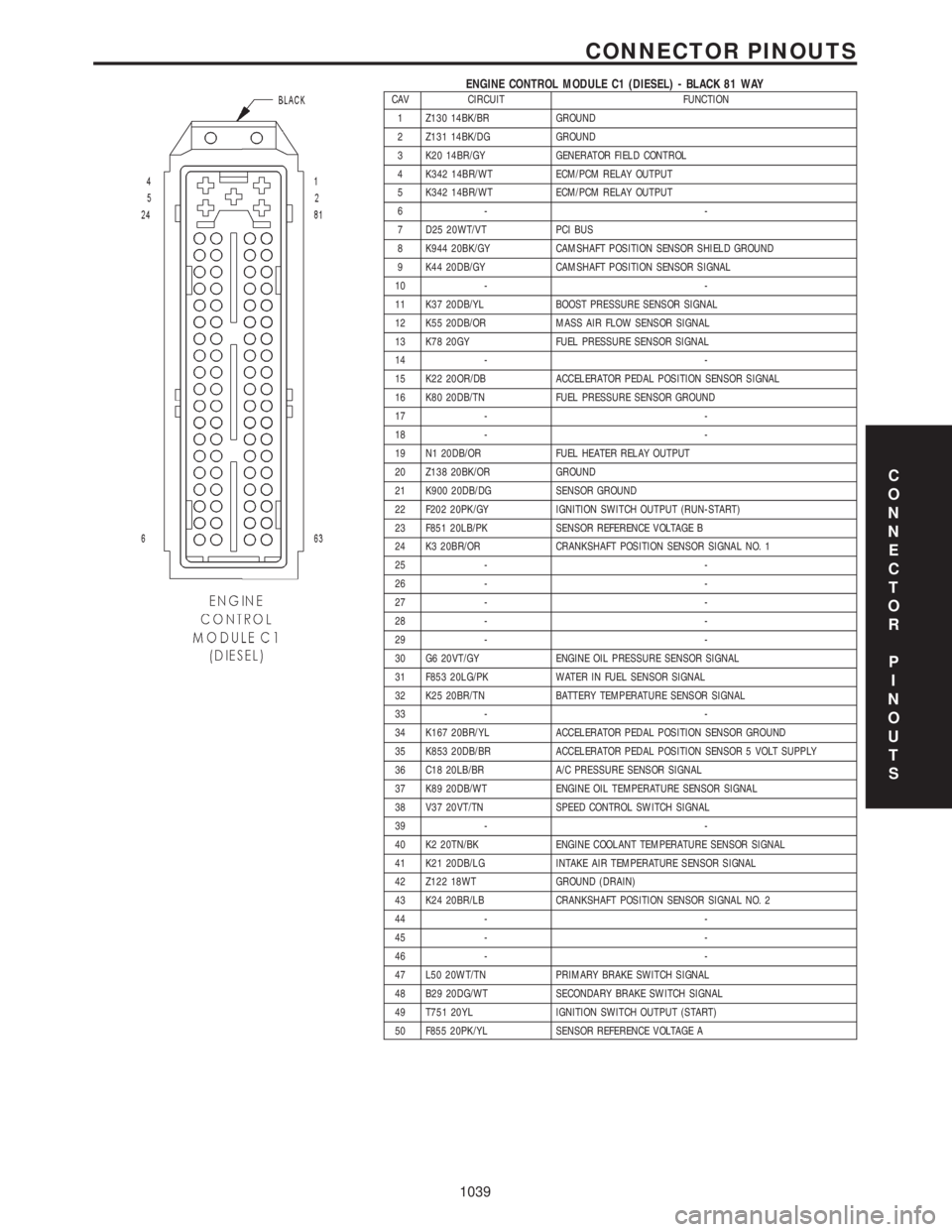
ENGINE CONTROL MODULE C1 (DIESEL) - BLACK 81 WAYCAV CIRCUIT FUNCTION
1 Z130 14BK/BR GROUND
2 Z131 14BK/DG GROUND
3 K20 14BR/GY GENERATOR FIELD CONTROL
4 K342 14BR/WT ECM/PCM RELAY OUTPUT
5 K342 14BR/WT ECM/PCM RELAY OUTPUT
6- -
7 D25 20WT/VT PCI BUS
8 K944 20BK/GY CAMSHAFT POSITION SENSOR SHIELD GROUND
9 K44 20DB/GY CAMSHAFT POSITION SENSOR SIGNAL
10 - -
11 K37 20DB/YL BOOST PRESSURE SENSOR SIGNAL
12 K55 20DB/OR MASS AIR FLOW SENSOR SIGNAL
13 K78 20GY FUEL PRESSURE SENSOR SIGNAL
14 - -
15 K22 20OR/DB ACCELERATOR PEDAL POSITION SENSOR SIGNAL
16 K80 20DB/TN FUEL PRESSURE SENSOR GROUND
17 - -
18 - -
19 N1 20DB/OR FUEL HEATER RELAY OUTPUT
20 Z138 20BK/OR GROUND
21 K900 20DB/DG SENSOR GROUND
22 F202 20PK/GY IGNITION SWITCH OUTPUT (RUN-START)
23 F851 20LB/PK SENSOR REFERENCE VOLTAGE B
24 K3 20BR/OR CRANKSHAFT POSITION SENSOR SIGNAL NO. 1
25 - -
26 - -
27 - -
28 - -
29 - -
30 G6 20VT/GY ENGINE OIL PRESSURE SENSOR SIGNAL
31 F853 20LG/PK WATER IN FUEL SENSOR SIGNAL
32 K25 20BR/TN BATTERY TEMPERATURE SENSOR SIGNAL
33 - -
34 K167 20BR/YL ACCELERATOR PEDAL POSITION SENSOR GROUND
35 K853 20DB/BR ACCELERATOR PEDAL POSITION SENSOR 5 VOLT SUPPLY
36 C18 20LB/BR A/C PRESSURE SENSOR SIGNAL
37 K89 20DB/WT ENGINE OIL TEMPERATURE SENSOR SIGNAL
38 V37 20VT/TN SPEED CONTROL SWITCH SIGNAL
39 - -
40 K2 20TN/BK ENGINE COOLANT TEMPERATURE SENSOR SIGNAL
41 K21 20DB/LG INTAKE AIR TEMPERATURE SENSOR SIGNAL
42 Z122 18WT GROUND (DRAIN)
43 K24 20BR/LB CRANKSHAFT POSITION SENSOR SIGNAL NO. 2
44 - -
45 - -
46 - -
47 L50 20WT/TN PRIMARY BRAKE SWITCH SIGNAL
48 B29 20DG/WT SECONDARY BRAKE SWITCH SIGNAL
49 T751 20YL IGNITION SWITCH OUTPUT (START)
50 F855 20PK/YL SENSOR REFERENCE VOLTAGE A
C
O
N
N
E
C
T
O
R
P
I
N
O
U
T
S
1039
CONNECTOR PINOUTS
Page 1069 of 4284
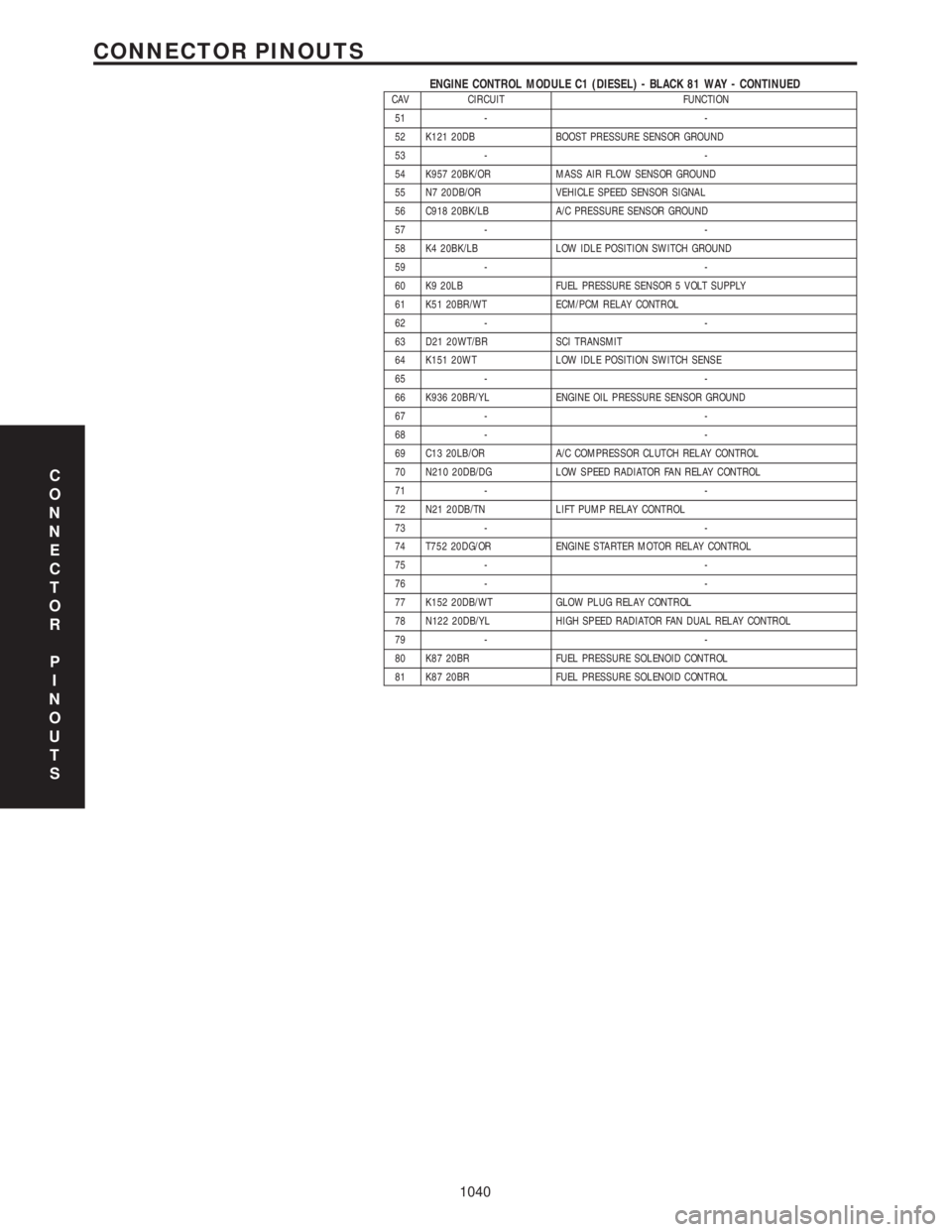
ENGINE CONTROL MODULE C1 (DIESEL) - BLACK 81 WAY - CONTINUEDCAV CIRCUIT FUNCTION
51 - -
52 K121 20DB BOOST PRESSURE SENSOR GROUND
53 - -
54 K957 20BK/OR MASS AIR FLOW SENSOR GROUND
55 N7 20DB/OR VEHICLE SPEED SENSOR SIGNAL
56 C918 20BK/LB A/C PRESSURE SENSOR GROUND
57 - -
58 K4 20BK/LB LOW IDLE POSITION SWITCH GROUND
59 - -
60 K9 20LB FUEL PRESSURE SENSOR 5 VOLT SUPPLY
61 K51 20BR/WT ECM/PCM RELAY CONTROL
62 - -
63 D21 20WT/BR SCI TRANSMIT
64 K151 20WT LOW IDLE POSITION SWITCH SENSE
65 - -
66 K936 20BR/YL ENGINE OIL PRESSURE SENSOR GROUND
67 - -
68 - -
69 C13 20LB/OR A/C COMPRESSOR CLUTCH RELAY CONTROL
70 N210 20DB/DG LOW SPEED RADIATOR FAN RELAY CONTROL
71 - -
72 N21 20DB/TN LIFT PUMP RELAY CONTROL
73 - -
74 T752 20DG/OR ENGINE STARTER MOTOR RELAY CONTROL
75 - -
76 - -
77 K152 20DB/WT GLOW PLUG RELAY CONTROL
78 N122 20DB/YL HIGH SPEED RADIATOR FAN DUAL RELAY CONTROL
79 - -
80 K87 20BR FUEL PRESSURE SOLENOID CONTROL
81 K87 20BR FUEL PRESSURE SOLENOID CONTROL
C
O
N
N
E
C
T
O
R
P
I
N
O
U
T
S
1040
CONNECTOR PINOUTS
Page 1100 of 4284
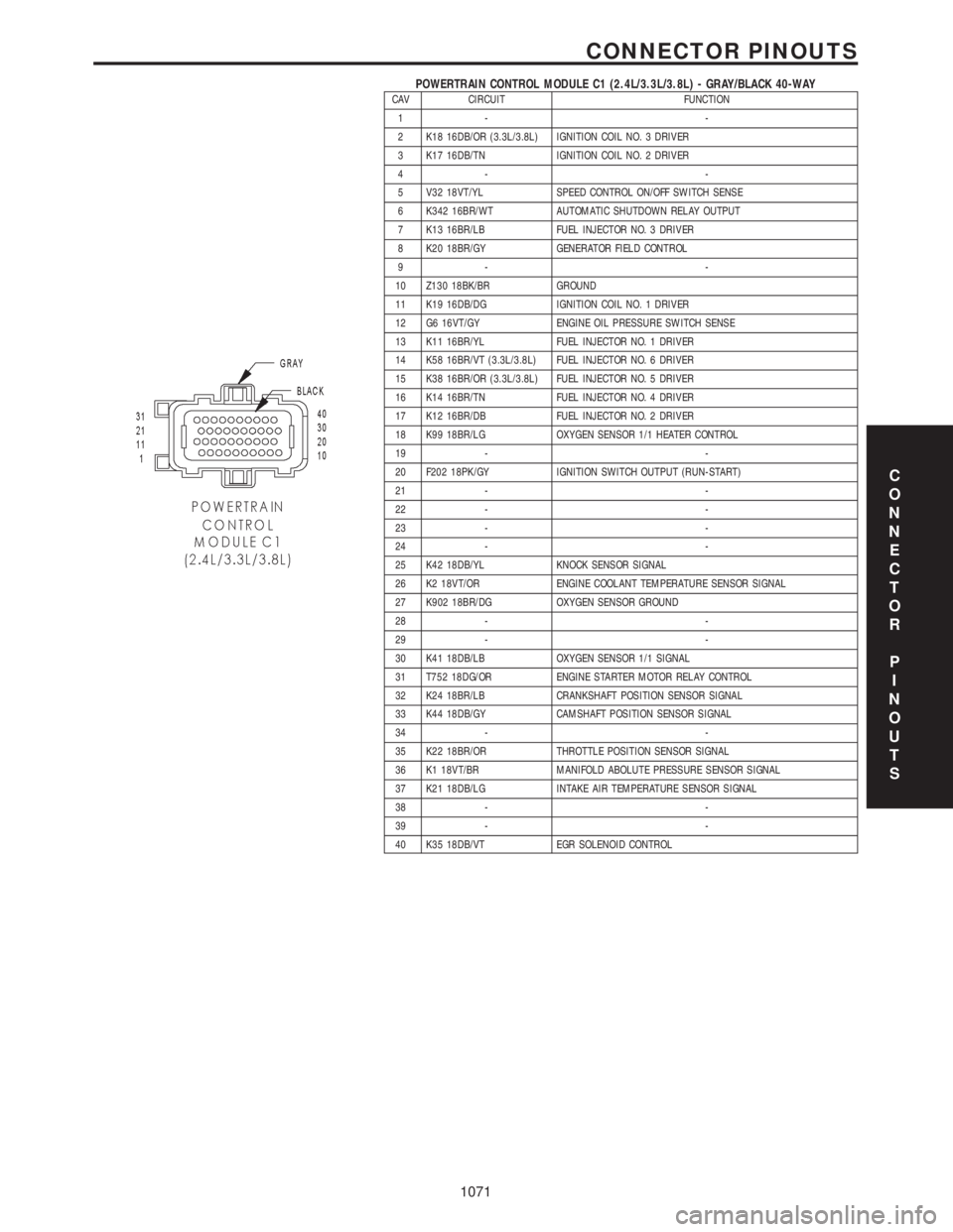
POWERTRAIN CONTROL MODULE C1 (2.4L/3.3L/3.8L) - GRAY/BLACK 40-WAYCAV CIRCUIT FUNCTION
1- -
2 K18 16DB/OR (3.3L/3.8L) IGNITION COIL NO. 3 DRIVER
3 K17 16DB/TN IGNITION COIL NO. 2 DRIVER
4- -
5 V32 18VT/YL SPEED CONTROL ON/OFF SWITCH SENSE
6 K342 16BR/WT AUTOMATIC SHUTDOWN RELAY OUTPUT
7 K13 16BR/LB FUEL INJECTOR NO. 3 DRIVER
8 K20 18BR/GY GENERATOR FIELD CONTROL
9- -
10 Z130 18BK/BR GROUND
11 K19 16DB/DG IGNITION COIL NO. 1 DRIVER
12 G6 16VT/GY ENGINE OIL PRESSURE SWITCH SENSE
13 K11 16BR/YL FUEL INJECTOR NO. 1 DRIVER
14 K58 16BR/VT (3.3L/3.8L) FUEL INJECTOR NO. 6 DRIVER
15 K38 16BR/OR (3.3L/3.8L) FUEL INJECTOR NO. 5 DRIVER
16 K14 16BR/TN FUEL INJECTOR NO. 4 DRIVER
17 K12 16BR/DB FUEL INJECTOR NO. 2 DRIVER
18 K99 18BR/LG OXYGEN SENSOR 1/1 HEATER CONTROL
19 - -
20 F202 18PK/GY IGNITION SWITCH OUTPUT (RUN-START)
21 - -
22 - -
23 - -
24 - -
25 K42 18DB/YL KNOCK SENSOR SIGNAL
26 K2 18VT/OR ENGINE COOLANT TEMPERATURE SENSOR SIGNAL
27 K902 18BR/DG OXYGEN SENSOR GROUND
28 - -
29 - -
30 K41 18DB/LB OXYGEN SENSOR 1/1 SIGNAL
31 T752 18DG/OR ENGINE STARTER MOTOR RELAY CONTROL
32 K24 18BR/LB CRANKSHAFT POSITION SENSOR SIGNAL
33 K44 18DB/GY CAMSHAFT POSITION SENSOR SIGNAL
34 - -
35 K22 18BR/OR THROTTLE POSITION SENSOR SIGNAL
36 K1 18VT/BR MANIFOLD ABOLUTE PRESSURE SENSOR SIGNAL
37 K21 18DB/LG INTAKE AIR TEMPERATURE SENSOR SIGNAL
38 - -
39 - -
40 K35 18DB/VT EGR SOLENOID CONTROL
C
O
N
N
E
C
T
O
R
P
I
N
O
U
T
S
1071
CONNECTOR PINOUTS