2001 CHRYSLER VOYAGER wheel bolts
[x] Cancel search: wheel boltsPage 32 of 4284
3.1.1 DRIVER AIRBAG
The airbag protective trim cover is the most
visible part of the driver side airbag system. The
protective trim cover is fitted to the front of the
airbag module and forms a decorative cover in the
center of the steering wheel. The module is
mounted directly to the steering wheel. Located
under the trim cover are the horn switch, the airbag
cushion, and the airbag cushion supporting compo-
nents. The airbag module includes a housing to
which the cushion and hybrid inflator are attached
and sealed. The 2001 Minivan is equipped with
driver airbag with dual stage inflators that include
a small canister of highly compressed argon gas.
The Occupant Restraint Controller (ORC) uses ve-
hicle crash severity, driver seat belt switch status
(buckled or unbuckled) as inputs to determine the
level of airbag deployment. When supplied with the
proper electrical signal, the hybrid inflator or infla-
tors discharge the compressed gas it contains di-
rectly into the cushion. The airbag module cannot
be repaired, and must be replaced if deployed or in
any way damaged.
WARNING: THE DRIVER AIRBAG MODULE
CONTAINS ARGON GAS PRESSURIZED TO
OVER 17236.89 Kpa (2500 PSI). DO NOT
ATTEMPT TO DISMANTLE AN AIRBAG
MODULE OR TAMPER WITH ITS INFLATOR.
DO NOT PUNCTURE, INCINERATE, OR
BRING INTO CONTACT WITH ELECTRICITY.
DO NOT STORE AT TEMPERATURE
EXCEEDING 93ÉC (200ÉF). REPLACE AIRBAG
SYSTEM COMPONENTS ONLY BUT
INTERNAL DIFFERENCES MAY RESULT IN
INFERIOR OCCUPANT PROTECTION. THE
FASTENERS, SCREWS, AND BOLTS
ORIGINALLY USED FOR THE AIRBAG
SYSTEM COMPONENTS HAVE SPECIAL
COATINGS AND ARE SPECIFICALLY
DESIGNED FOR THE AIRBAG SYSTEM. THEY
MUST NEVER BE REPLACED WITH ANY
SUBSTITUTES. ANY TIME A NEW FASTENER
IS NEEDED, REPLACE IT WITH THE
CORRECT FASTENERS PROVIDED IN THE
SERVICE PACKAGE OR SPECIFIED IN THE
MOPAR PARTS CATALOG.
CAUTION: Deployed Front Air Bags may or may not have live pyrotechnic material within the
air bag inflator. Do not dispose of 2001 Model Year Driver and Passenger Airbags unless you
are sure of complete deployment. Please refer to the Hazardous Substance Control System for
Proper Disposal. Dispose of deployed air bags in a manner consistent with state, provincial,
local, and federal regulations. Use the following table to identify the status of the Airbag Squib.
AIRBAG SQUIB STATUS
(1) Using a DRBIIItread Airbag DTC'sIfthe following active codes are present:
ACTIVE DTC CONDITIONS SQUIB STATUS
Driver Squib 1 open
Driver Squib 2 openCheck the stored DTC'sAND IFthe stored min-
utes for both are within 15 minutes of each other.Both Driver Squib 1
and 2 were used.
Driver Squib 1 open
Driver Squib 2 openCheck the stored DTC'sAND IFthe stored min-
utes for Driver Squib 2 open is GREATER than
the stored minutes for Driver Squib 1 by 15 min-
utes or more.Driver Squib 1 was
used;
Driver Squib 2 is live.
Driver Squib 1 open
Driver Squib 2 openCheck the stored DTC'sAND IFthe stored min-
utes for Driver Squib 1 open is GREATER than
the stored minutes for Driver Squib 2 by 15 min-
utes or more.Driver Squib 1 is live;
Driver Squib 2 was
used.
IfDriver Squib 1 openAND IFDriver Squib 2 opens is NOT an active
code.Driver Squib 1 was
used;
Driver Squib 2 is live.
IfDriver Squib 2 openAND IFDriver Squib 1 open is NOT an active
code.Driver Squib 1 is live;
Driver Squib 2 was
used.
3
GENERAL INFORMATION
Page 33 of 4284
Ifneither of the following codes is an active code:
ACTIVE DTC SQUIB STATUS
Driver squib 1 open Status of Airbag is
Driver Squib 2 open Unknown.
3.1.2 CLOCKSPRING
The clockspring is mounted on the steering col-
umn behind the steering wheel. This assembly
consist of a plastic housing which contains a flat,
ribbon-like, electrically conductive tape that winds
and unwinds with the steering wheel rotation. The
clockspring is used to maintain a continuous elec-
trical circuit between the instrument panel wiring
and the driver airbag, the horn, and the vehicle
speed control switches if equipped. The clockspring
must be properly centered when it is reinstalled on
the steering column following any service proce-
dure, or it could be damaged. The clockspring can-
not be repaired and it must be replaced.
3.1.3 PASSENGER AIRBAG
The airbag door in the instrument panel top cover
the glove box is the most visible part of the passen-
ger side airbag system. The airbag door has a living
hinge at the top, which is secured to the instrument
panel top cover. Located under the airbag door is
the airbag cushion and its supporting components.
The airbag module includes a housing to which the
cushion and hybrid inflators are attached and
sealed. The 2001 Minivan is equipped with front
passenger airbag with dual stage inflators that
include a small canister of highly compressed argon
gas. The ORC uses vehicle crash severity, front
passenger seat belt switch status (buckled or un-
buckled) inputs to determine the level of airbag
deployment. When supplied with the proper electri-
cal signal, the hybrid inflator or inflators discharge
the compressed gas it contains directly into the
cushion. The airbag module cannot be repaired, and
must be replaced if deployed or in any way dam-
aged.
WARNING: THE PASSENGER AIRBAG
MODULE CONTAINS ARGON GAS
PRESSURIZED TO 17236.89 Kpa (2500 PSI).
DO NOT ATTEMPT TO DISMANTLE AN
AIRBAG MODULE OR TAMPER WITH ITS
INFLATOR. DO NOT PUNCTURE,
INCINERATE, OR BRING INTO CONTACT
WITH ELECTRICITY. DO NOT STORE AT
TEMPERATURE EXCEEDING 93ÉC (200ÉF).
REPLACE AIRBAG SYSTEM COMPONENTS
ONLY WITH PARTS SPECIFIED IN THE
MOPAR PARTS CATALOG. SUBSTITUTE
PARTS MAY APPEAR INTERCHANGEABLE,
BUT INTERNAL DIFFERENCES MAY RESULT
IN INFERIOR OCCUPANT PROTECTION. THE
FASTENERS, SCREWS, AND BOLTS
ORIGINALLY USED FOR THE AIRBAG
SYSTEM COMPONENTS HAVE SPECIAL
COATINGS AND ARE SPECIFICALLY
DESIGNED FOR THE AIRBAG SYSTEM. THEY
MUST NEVER BE REPLACED WITH ANY
SUBSTITUTES. ANY TIME A NEW FASTENER
IS NEEDED, REPLACE IT WITH THE
CORRECT FASTENERS PROVIDED IN THE
SERVICE PACKAGE OR SPECIFIED IN THE
MOPAR PARTS CATALOG.
4
GENERAL INFORMATION
Page 35 of 4284
if the system is functioning properly. If the test
finds a problem the SIACM will set both active and
stored diagnostic trouble codes. If a DTC is active
the SIACM will request that the airbag warning
lamp be turned on. The results of the system test
are transmitted on the PCI Bus to the ORC once
each second or on change in lamp state. If the
warning lamp status message from the either SI-
ACM contains a lamp on request, the ORC will set
an active DTC. At the same time as the DTC is set
the ORC sends a PCI Bus message to the mechan-
ical instrument cluster (MIC) requesting the airbag
warning lamp be turned on. Observe all ORC warn-
ing and caution statements when servicing or han-
dling the SIACM. SIACM are not repairable and
must be replaced if they are dropped.
WARNING: THE AIRBAG SYSTEM IS A
SENSITIVE, COMPLEX ELECTRO-
MECHANICAL UNIT. BEFORE ATTEMPTING
TO DIAGNOSE OR SERVICE ANY AIRBAG
SYSTEM OR RELATED STEERING WHEEL,
STEERING COLUMN, OR INSTRUMENT
PANEL COMPONENTS YOU MUST FIRST
DISCONNECT AND ISOLATE THE BATTERY
NEGATIVE (GROUND) CABLE. WAIT TWO
MINUTES FOR THE SYSTEM CAPACITOR TO
DISCHARGE BEFORE FURTHER SYSTEM
SERVICE. THIS IS THE ONLY SURE WAY TO
DISABLE THE AIRBAG SYSTEM. FAILURE
TO DO THIS COULD RESULT IN ACCIDENTAL
AIRBAG DEPLOYMENT AND POSSIBLE
PERSONAL INJURY. NEVER STRIKE OR
KICK THE AIRBAG CONTROL MODULE, AS
IT CAN DAMAGE THE IMPACT SENSOR OR
AFFECT ITS CALIBRATION. IF AN AIRBAG
CONTROL MODULE IS ACCIDENTALLY
DROPPED DURING SERVICE, THE MODULE
MUST BE SCRAPPED AND REPLACED WITH
A NEW UNIT.
The airbag warning lamp is the only point at
which the customer can observe symptoms of a
system malfunction. Whenever the ignition key is
turned to the run or start position, the MIC per-
forms a lamp check by turning the airbag warning
indicator on for 6-8 seconds. After the lamp check, if
the indicator turns on, it means that the ORC has
checked the system and found it to be free of
discernible malfuctions. If the lamp remains on,
there could be an active fault in the system or the
MIC lamp circuit may be internally shorted to
ground. If the lamp comes on and stays on for a
period longer than 6-8 seconds then goes off, there
is usually an intermittent problem in the system.
3.1.7 SEAT AIRBAGS (SAB)
The left and right seat airbag modules are located
in the outboard end of the front seat backs. The
airbag module contains a bag, an inflator (a small
canister of highly compressed argon gas) and a
mounting bracket. The seat airbag module cannot
be repaired and must be replaced if deployed or in
any way damaged. When supplied with the proper
electrical signal the inflator seals the hole in the
airbag cushion so it can discharge the compressed
gas it contains directly into the cushion. Upon
deployment, the seat back trim cover will tear open
and allow the seat airbag to fully deploy between
the seat and the door.
WARNING: SEAT AIRBAG CONTAINS ARGON
GAS PRESSURIZED TO OVER 17236.89 Kpa
(2500 PSI). DO NOT ATTEMPT TO
DISMANTLE AN AIRBAG MODULE OR
TAMPER WITH ITS INFLATOR. DO NOT
PUNCTURE, INCINERATE, OR BRING INTO
CONTACT WITH ELECTRICITY. DO NOT
STORE AT TEMPERATURE EXCEEDING 93ÉC
(200ÉF). REPLACE AIRBAG SYSTEM
COMPONENTS ONLY WITH PARTS
SPECIFIED IN THE CHRYSLER MOPAR
PARTS CATALOG. SUBSTITUTE PARTS MAY
APPEAR INTERCHANGEABLE, BUT
INTERNAL DIFFERENCES MAY RESULT IN
INFERIOR OCCUPANT PROTECTION. THE
FASTENERS, SCREWS, AND BOLTS
ORIGINALLY USED FOR THE AIRBAG
SYSTEM COMPONENTS HAVE SPECIAL
COATINGS AND ARE SPECIFICALLY
DESIGNED FOR THE AIRBAG SYSTEM. THEY
MUST NEVER BE REPLACED WITH ANY
SUBSTITUTES. ANY TIME A NEW FASTENER
IS NEEDED, REPLACE IT WITH THE
CORRECT FASTENERS PROVIDED IN THE
SERVICE PACKAGE OR SPECIFIED IN THE
MOPAR PARTS CATALOG.
3.1.8 ORC/SIACM DIAGNOSTIC TROUBLE
CODES
Airbag diagnostic trouble codes consist of active
and stored codes. If more than one code exists,
diagnostic priority should be given to the active
codes. Each diagnostic trouble code is diagnosed by
following a specific testing procedure. The diagnos-
tic test procedures contain step-by-step instructions
for determining the cause of the trouble codes. It is
not necessary to perform all of the tests in this book
to diagnose an individual code. Always begin by
reading the diagnostic trouble codes using the DRB.
Always begin diagnostic with the Table of Contents
6
GENERAL INFORMATION
Page 1506 of 4284
GROUND CLEARANCE
CAUTION: If vehicle is towed with wheels removed,
install lug nuts to retain brake drums or rotors.
A towed vehicle should be raised until the lifted
wheels are a minimum 100 mm (4 in.) from the
ground. Be sure there is at least 100 mm (4 in.)
clearance between the tail pipe and the ground. If
necessary, remove the wheels from the lifted end of
the vehicle and lower the vehicle closer to the
ground, to increase the ground clearance at the rear
of the vehicle. Install lug nuts on wheel attaching
studs to retain brake drums or rotors.
LOCKED VEHICLE TOWING
When a locked vehicle must be towed with the
front wheels on the ground, use a towing dolly or flat
bed hauler.
FLAT TOWING WITH TOW BAR
²Three speed automatic transaxle vehicles can be
flat towed at speeds not to exceed 40 km/h (25 mph)
for not more than 25 km (15 miles). The steering col-
umn must be unlocked and gear selector in neutral.
²Four speed electronic automatic transaxle vehi-
cles can be flat towed at speeds not to exceed 72
km/h (44 mph) for not more than 160 km (100 miles).
The steering column must be unlocked and gear
selector in neutral.
²AWD models should not be flat towed. For addi-
tional information, refer toRECOMMENDED TOW-
ING EQUIPMENTin this section.
FLAT BED TOWING TIE DOWNS
CAUTION: Do not tie vehicle down by attaching
chains or cables to suspension components or
engine mounts, damage to vehicle can result.
The vehicle can be tied to a flat bed device using
the two pair of front slots on the bottom surface of
the rails, behind the front wheels. The two pair of
rear slots on the bottom of the rail between the
bumper extension bolts and on the bottom of the rail
just rearward of the jounce bumper. Vehicles
equipped with a rear sway bar have brackets at this
location.
TOWING ± FRONT WHEEL LIFT
If the vehicle is being towed from the front, when-
ever possible ensure at lest 10 inches road clearness
to the tires.
TOWING ± REAR WHEEL LIFT
If a vehicle cannot be towed with the front wheels
lift, the rear wheels can be lifted provided the follow-
ing guide lines are observed.
CAUTION: Do not use steering column lock to
secure steering wheel during towing operation.
²On AWD vehicles, all four wheels must be free to
rotate. Use towing dollies at unlifted end of vehicle.
²Unlock steering column and secure steering
wheel in straight ahead position with a clamp device
designed for towing.
²Three speed automatic transaxle vehicles can be
flat towed at speeds not to exceed 40 km/h (25 mph)
for not more than 25 km (15 miles). The steering col-
umn must be unlocked and gear selector in neutral.
²Four speed electronic automatic transaxle vehi-
cles can be flat towed at speeds not to exceed 72
km/h (44 mph) for not more than 160 km (100 miles).
The steering column must be unlocked and gear
selector in neutral.
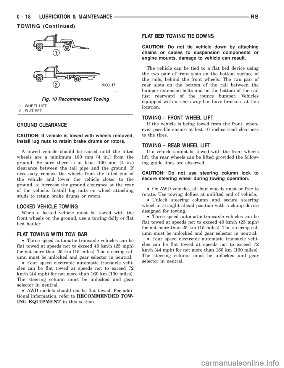
Fig. 10 Recommended Towing
1 - WHEEL LIFT
2 - FLAT BED
0 - 18 LUBRICATION & MAINTENANCERS
TOWING (Continued)
Page 1515 of 4284
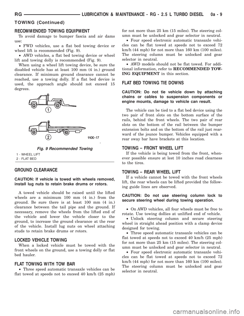
RECOMMENDED TOWING EQUIPMENT
To avoid damage to bumper fascia and air dams
use:
²FWD vehicles, use a flat bed towing device or
wheel lift is recommended (Fig. 9).
²AWD vehicles, a flat bed towing device or wheel
lift and towing dolly is recommended (Fig. 9).
When using a wheel lift towing device, be sure the
disabled vehicle has at least 100 mm (4 in.) ground
clearance. If minimum ground clearance cannot be
reached, use a towing dolly. If a flat bed device is
used, the approach angle should not exceed 15
degrees.
GROUND CLEARANCE
CAUTION: If vehicle is towed with wheels removed,
install lug nuts to retain brake drums or rotors.
A towed vehicle should be raised until the lifted
wheels are a minimum 100 mm (4 in.) from the
ground. Be sure there is at least 100 mm (4 in.)
clearance between the tail pipe and the ground. If
necessary, remove the wheels from the lifted end of
the vehicle and lower the vehicle closer to the
ground, to increase the ground clearance at the rear
of the vehicle. Install lug nuts on wheel attaching
studs to retain brake drums or rotors.
LOCKED VEHICLE TOWING
When a locked vehicle must be towed with the
front wheels on the ground, use a towing dolly or flat
bed hauler.
FLAT TOWING WITH TOW BAR
²Three speed automatic transaxle vehicles can be
flat towed at speeds not to exceed 40 km/h (25 mph)for not more than 25 km (15 miles). The steering col-
umn must be unlocked and gear selector in neutral.
²Four speed electronic automatic transaxle vehi-
cles can be flat towed at speeds not to exceed 72
km/h (44 mph) for not more than 160 km (100 miles).
The steering column must be unlocked and gear
selector in neutral.
²AWD models should not be flat towed. For addi-
tional information, refer toRECOMMENDED TOW-
ING EQUIPMENTin this section.
FLAT BED TOWING TIE DOWNS
CAUTION: Do not tie vehicle down by attaching
chains or cables to suspension components or
engine mounts, damage to vehicle can result.
The vehicle can be tied to a flat bed device using the
two pair of front slots on the bottom surface of the
rails, behind the front wheels. The two pair of rear
slots on the bottom of the rail between the bumper
extension bolts and on the bottom of the rail just rear-
ward of the jounce bumper. Vehicles equipped with a
rear sway bar have brackets at this location.
TOWING ± FRONT WHEEL LIFT
If the vehicle is being towed from the front, when-
ever possible ensure at lest 10 inches road clearness
to the tires.
TOWING ± REAR WHEEL LIFT
If a vehicle cannot be towed with the front wheels
lift, the rear wheels can be lifted provided the follow-
ing guide lines are observed.
CAUTION: Do not use steering column lock to
secure steering wheel during towing operation.
²On AWD vehicles, all four wheels must be free to
rotate. Use towing dollies at unlifted end of vehicle.
²Unlock steering column and secure steering
wheel in straight ahead position with a clamp device
designed for towing.
²Three speed automatic transaxle vehicles can be
flat towed at speeds not to exceed 40 km/h (25 mph)
for not more than 25 km (15 miles). The steering col-
umn must be unlocked and gear selector in neutral.
²Four speed electronic automatic transaxle vehi-
cles can be flat towed at speeds not to exceed 72
km/h (44 mph) for not more than 160 km (100 miles).
The steering column must be unlocked and gear
selector in neutral.
Fig. 9 Recommended Towing
1 - WHEEL LIFT
2 - FLAT BED
RGLUBRICATION & MAINTENANCE - RG - 2.5 L TURBO DIESEL0a-9
TOWING (Continued)
Page 1519 of 4284
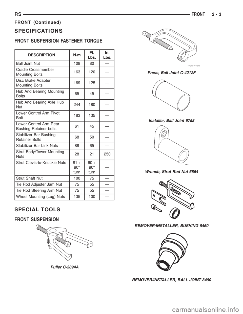
SPECIFICATIONS
FRONT SUSPENSION FASTENER TORQUE
DESCRIPTION N´mFt.
Lbs.In.
Lbs.
Ball Joint Nut 108 80 Ð
Cradle Crossmember
Mounting Bolts163 120 Ð
Disc Brake Adapter
Mounting Bolts169 125 Ð
Hub And Bearing Mounting
Bolts65 45 Ð
Hub And Bearing Axle Hub
Nut244 180 Ð
Lower Control Arm Pivot
Bolt183 135 Ð
Lower Control Arm Rear
Bushing Retainer bolts61 45 Ð
Stabilizer Bar Bushing
Retainer Bolts68 50 Ð
Stabilizer Bar Link Nuts 88 65 Ð
Strut Body/Tower Mounting
Nuts28 21 250
Strut Clevis-to-Knuckle Nuts 81 +
90É
turn60 +
90É
turnÐ
Strut Shaft Nut 100 75 Ð
Tie Rod Adjuster Jam Nut 75 55 Ð
Tie Rod Steering Arm Nut 75 55 Ð
Wheel Mounting (Lug) Nuts 135 100 Ð
SPECIAL TOOLS
FRONT SUSPENSION
Puller C-3894A
Press, Ball Joint C-4212F
Installer, Ball Joint 6758
Wrench, Strut Rod Nut 6864
REMOVER/INSTALLER, BUSHING 8460
REMOVER/INSTALLER, BALL JOINT 8490
RSFRONT2-3
FRONT (Continued)
Page 1520 of 4284
BUSHINGS
REMOVAL - STABILIZER BAR CUSHION
(1) Raise Vehicle. Refer to Hoisting in Lubrication
and Maintenance.
(2) Remove the 2 bolts fastening the emission leak
detection pump to the cradle crossmember reinforce-
ment.
(3) Move the leak detection pump to the side
allowing access to the stabilizer bar cushion retain-
ers.
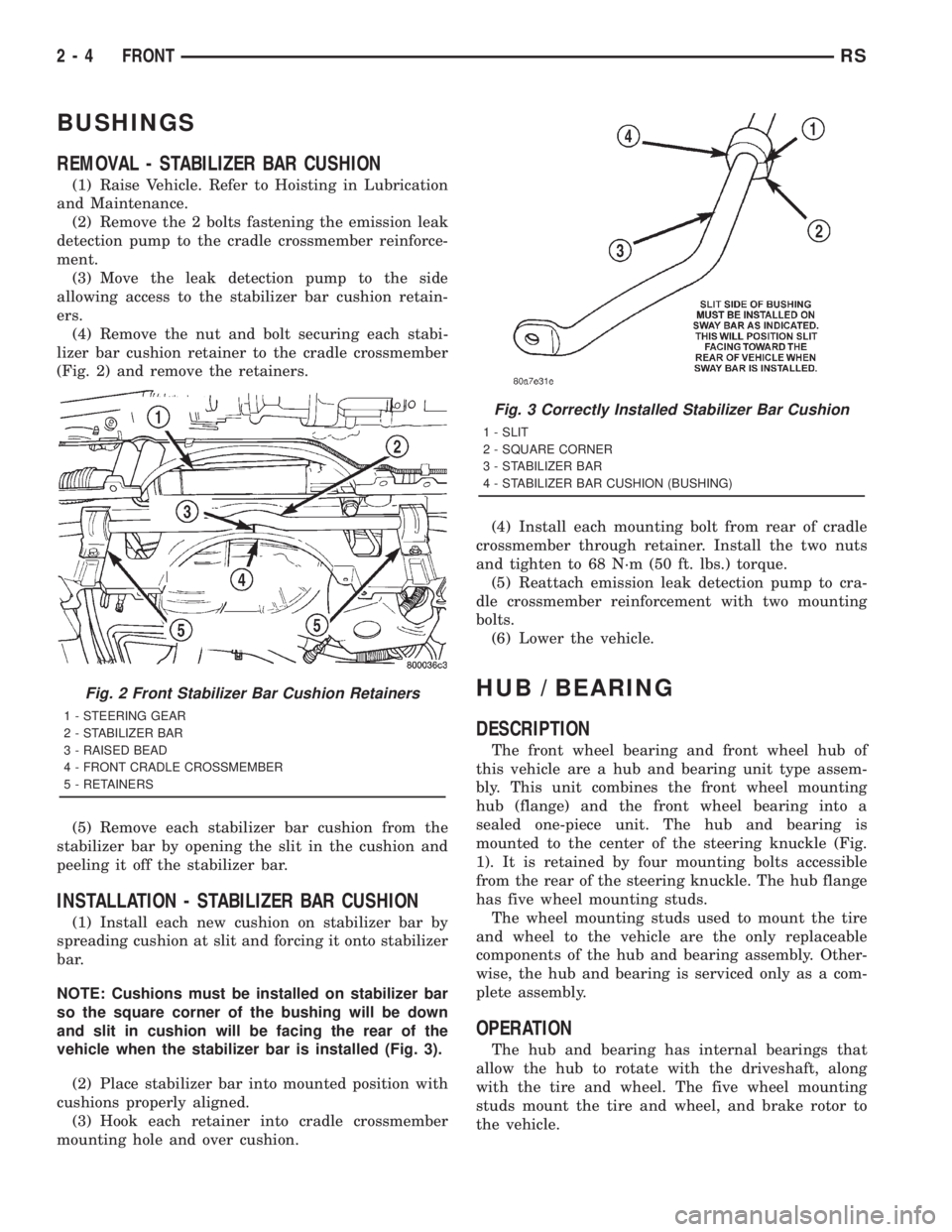
(4) Remove the nut and bolt securing each stabi-
lizer bar cushion retainer to the cradle crossmember
(Fig. 2) and remove the retainers.
(5) Remove each stabilizer bar cushion from the
stabilizer bar by opening the slit in the cushion and
peeling it off the stabilizer bar.
INSTALLATION - STABILIZER BAR CUSHION
(1) Install each new cushion on stabilizer bar by
spreading cushion at slit and forcing it onto stabilizer
bar.
NOTE: Cushions must be installed on stabilizer bar
so the square corner of the bushing will be down
and slit in cushion will be facing the rear of the
vehicle when the stabilizer bar is installed (Fig. 3).
(2) Place stabilizer bar into mounted position with
cushions properly aligned.
(3) Hook each retainer into cradle crossmember
mounting hole and over cushion.(4) Install each mounting bolt from rear of cradle
crossmember through retainer. Install the two nuts
and tighten to 68 N´m (50 ft. lbs.) torque.
(5) Reattach emission leak detection pump to cra-
dle crossmember reinforcement with two mounting
bolts.
(6) Lower the vehicle.
HUB / BEARING
DESCRIPTION
The front wheel bearing and front wheel hub of
this vehicle are a hub and bearing unit type assem-
bly. This unit combines the front wheel mounting
hub (flange) and the front wheel bearing into a
sealed one-piece unit. The hub and bearing is
mounted to the center of the steering knuckle (Fig.
1). It is retained by four mounting bolts accessible
from the rear of the steering knuckle. The hub flange
has five wheel mounting studs.
The wheel mounting studs used to mount the tire
and wheel to the vehicle are the only replaceable
components of the hub and bearing assembly. Other-
wise, the hub and bearing is serviced only as a com-
plete assembly.
OPERATION
The hub and bearing has internal bearings that
allow the hub to rotate with the driveshaft, along
with the tire and wheel. The five wheel mounting
studs mount the tire and wheel, and brake rotor to
the vehicle.
Fig. 2 Front Stabilizer Bar Cushion Retainers
1 - STEERING GEAR
2 - STABILIZER BAR
3 - RAISED BEAD
4 - FRONT CRADLE CROSSMEMBER
5 - RETAINERS
Fig. 3 Correctly Installed Stabilizer Bar Cushion
1 - SLIT
2 - SQUARE CORNER
3 - STABILIZER BAR
4 - STABILIZER BAR CUSHION (BUSHING)
2 - 4 FRONTRS
Page 1521 of 4284
DIAGNOSIS AND TESTING - HUB AND
BEARING (FRONT)
The condition of the front hub and bearing assem-
bly is diagnosed using the inspection and testing pro-
cedure detailed below.
The bearing contained in the Unit III front hub/
bearing assembly will produce noise and vibration
when worn or damaged. The noise will generally
change when the bearings are loaded. A road test of
the vehicle is normally required to determine the
location of a worn or damaged bearing.
Find a smooth level road surface and bring the
vehicle up to a constant speed. When vehicle is at a
constant speed, swerve the vehicle back and forth
from the left and to the right. This will load and
unload the bearings and change the noise level.
Where axle bearing damage is slight, the noise is
usually not noticeable at speeds above 48 km/h (30
mph).
REMOVAL - HUB AND BEARING
NOTE: Replacement of the Unit III front hub/bearing
assembly can be normally done without having to
remove the steering knuckle from the vehicle. In the
event that the hub/bearing is frozen in the steering
knuckle and cannot be removed by hand, it will
have to be pressed out of the steering knuckle. The
steering knuckle will require removal from the vehi-
cle to allow the hub/bearing assembly to be
pressed out of the steering knuckle. (Refer to 2 -
SUSPENSION/FRONT/KNUCKLE - REMOVAL)
(1) Raise vehicle on jack stands or centered on a
frame contact type hoist. See Hoisting in Lubrication
and Maintenance.
(2) Remove wheel lug nuts, and front tire and
wheel assembly.
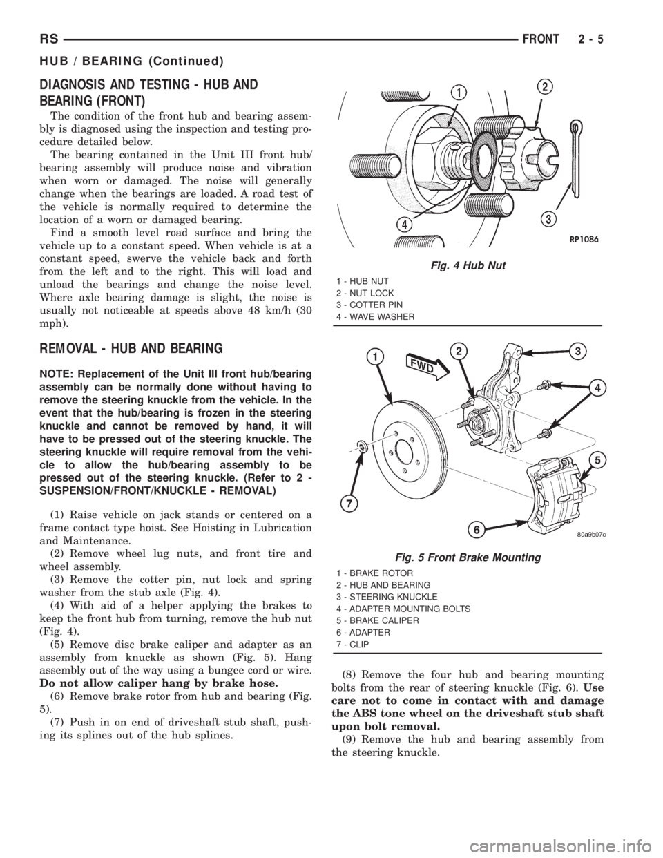
(3) Remove the cotter pin, nut lock and spring
washer from the stub axle (Fig. 4).
(4) With aid of a helper applying the brakes to
keep the front hub from turning, remove the hub nut
(Fig. 4).
(5) Remove disc brake caliper and adapter as an
assembly from knuckle as shown (Fig. 5). Hang
assembly out of the way using a bungee cord or wire.
Do not allow caliper hang by brake hose.
(6) Remove brake rotor from hub and bearing (Fig.
5).
(7) Push in on end of driveshaft stub shaft, push-
ing its splines out of the hub splines.(8) Remove the four hub and bearing mounting
bolts from the rear of steering knuckle (Fig. 6).Use
care not to come in contact with and damage
the ABS tone wheel on the driveshaft stub shaft
upon bolt removal.
(9) Remove the hub and bearing assembly from
the steering knuckle.
Fig. 4 Hub Nut
1 - HUB NUT
2 - NUT LOCK
3 - COTTER PIN
4 - WAVE WASHER
Fig. 5 Front Brake Mounting
1 - BRAKE ROTOR
2 - HUB AND BEARING
3 - STEERING KNUCKLE
4 - ADAPTER MOUNTING BOLTS
5 - BRAKE CALIPER
6 - ADAPTER
7 - CLIP
RSFRONT2-5
HUB / BEARING (Continued)