2001 CHRYSLER VOYAGER stop start
[x] Cancel search: stop startPage 39 of 4284
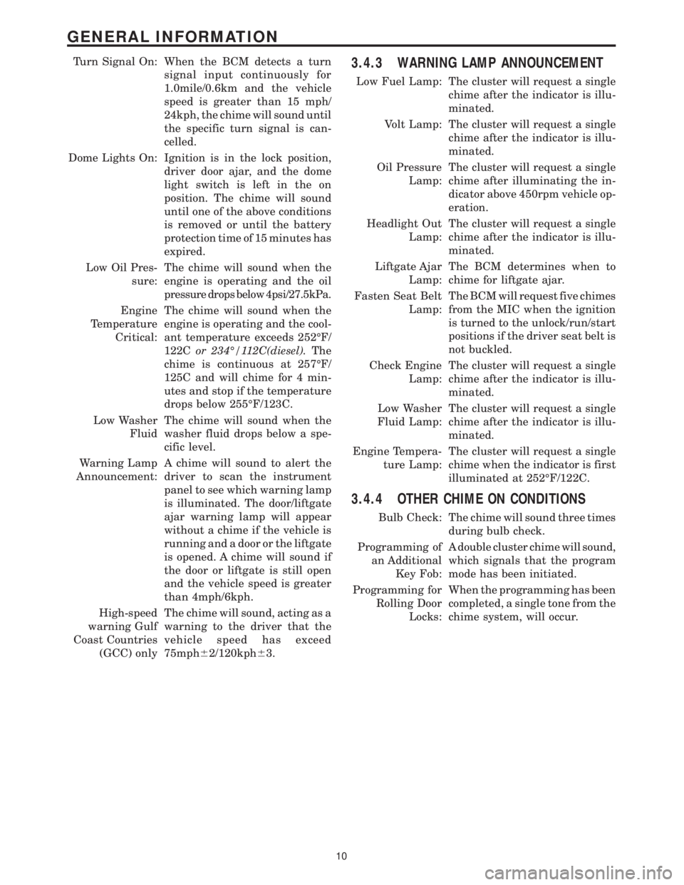
Turn Signal On: When the BCM detects a turn
signal input continuously for
1.0mile/0.6km and the vehicle
speed is greater than 15 mph/
24kph, the chime will sound until
the specific turn signal is can-
celled.
Dome Lights On: Ignition is in the lock position,
driver door ajar, and the dome
light switch is left in the on
position. The chime will sound
until one of the above conditions
is removed or until the battery
protection time of 15 minutes has
expired.
Low Oil Pres-
sure:The chime will sound when the
engine is operating and the oil
pressure drops below 4psi/27.5kPa.
Engine
Temperature
Critical:The chime will sound when the
engine is operating and the cool-
ant temperature exceeds 252ÉF/
122Cor 234É/112C(diesel).The
chime is continuous at 257ÉF/
125C and will chime for 4 min-
utes and stop if the temperature
drops below 255ÉF/123C.
Low Washer
FluidThe chime will sound when the
washer fluid drops below a spe-
cific level.
Warning Lamp
Announcement:A chime will sound to alert the
driver to scan the instrument
panel to see which warning lamp
is illuminated. The door/liftgate
ajar warning lamp will appear
without a chime if the vehicle is
running and a door or the liftgate
is opened. A chime will sound if
the door or liftgate is still open
and the vehicle speed is greater
than 4mph/6kph.
High-speed
warning Gulf
Coast Countries
(GCC) onlyThe chime will sound, acting as a
warning to the driver that the
vehicle speed has exceed
75mph62/120kph63.3.4.3 WARNING LAMP ANNOUNCEMENT
Low Fuel Lamp: The cluster will request a single
chime after the indicator is illu-
minated.
Volt Lamp: The cluster will request a single
chime after the indicator is illu-
minated.
Oil Pressure
Lamp:The cluster will request a single
chime after illuminating the in-
dicator above 450rpm vehicle op-
eration.
Headlight Out
Lamp:The cluster will request a single
chime after the indicator is illu-
minated.
Liftgate Ajar
Lamp:The BCM determines when to
chime for liftgate ajar.
Fasten Seat Belt
Lamp:The BCM will request five chimes
from the MIC when the ignition
is turned to the unlock/run/start
positions if the driver seat belt is
not buckled.
Check Engine
Lamp:The cluster will request a single
chime after the indicator is illu-
minated.
Low Washer
Fluid Lamp:The cluster will request a single
chime after the indicator is illu-
minated.
Engine Tempera-
ture Lamp:The cluster will request a single
chime when the indicator is first
illuminated at 252ÉF/122C.
3.4.4 OTHER CHIME ON CONDITIONS
Bulb Check: The chime will sound three times
during bulb check.
Programming of
an Additional
Key Fob:A double cluster chime will sound,
which signals that the program
mode has been initiated.
Programming for
Rolling Door
Locks:When the programming has been
completed, a single tone from the
chime system, will occur.
10
GENERAL INFORMATION
Page 42 of 4284
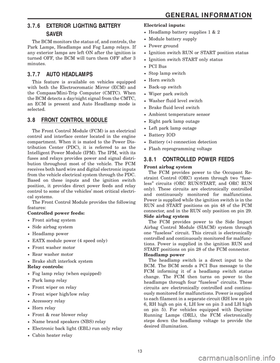
3.7.6 EXTERIOR LIGHTING BATTERY
SAVER
The BCM monitors the status of, and controls, the
Park Lamps, Headlamps and Fog Lamp relays. If
any exterior lamps are left ON after the ignition is
turned OFF, the BCM will turn them OFF after 3
minutes.
3.7.7 AUTO HEADLAMPS
This feature is available on vehicles equipped
with both the Electrocromatic Mirror (ECM) and
the Compass/Mini-Trip Computer (CMTC). When
the BCM detects a day/night signal from the CMTC,
an ECM is present and Auto Headlamp mode is
selected.
3.8 FRONT CONTROL MODULE
The Front Control Module (FCM) is an electrical
control and interface center located in the engine
compartment. When it is mated to the Power Dis-
tribution Center (PDC), it is referred to as the
Intelligent Power Module (IPM). The IPM, with its
fuses and relays provides power and signal distri-
bution throughout most of the vehicle. The FCM
receives both hard wire and digital electronic inputs
from the vehicle electrical system through the PDC.
Based on these inputs and the ignition switch
position, it provides direct power feeds and relay
control to some of the vehicles' most critical electri-
cal systems.
The Front Control Module provides the following
features:
Controlled power feeds:
²Front airbag system
²Side airbag system
²Headlamp power
²EATX module power (4 speed only)
²Front washer motor
²Rear washer motor
²Brake shift interlock system
Relay controls:
²Fog lamp relay (when equipped)
²Park lamp relay
²Front wiper on relay
²Front wiper high/low relay
²Accessory relay
²Horn relay
²Front & rear blower relay
²Name brand speakers (NBS) relay
²Electronic back light (EBL) run only relay
²Cabin heater relayElectrical inputs:
²Headlamp battery supplies1&2
²Module battery supply
²Power ground
²Ignition switch RUN or START position status
²Ignition switch START only status
²PCI Bus
²Stop lamp switch
²Horn switch
²Back-up switch
²Wiper park switch
²Washer fluid level switch
²Brake fluid level switch
²Ambient temperature sensor
²Right park lamp outage
²Left park lamp outage
²Battery IOD
²Battery (+) connection detection
²Flash reprogramming voltage
3.8.1 CONTROLLED POWER FEEDS
Front airbag system
The FCM provides power to the Occupant Re-
straint Control (ORC) system through two ªfuse-
lessº circuits (ORC RUN/START, and ORC RUN
only). These circuits are electronically controlled
and continuously monitored for malfunctions.
Power is supplied while the ignition switch is in the
RUN and START positions on pin 48 of the FCM
connector, and in the RUN only position on pin 29.
Side airbag system
The FCM provides power to the Side Impact
Airbag Control Module (SIACM) system through
one ªfuselessº circuit. This circuit is electronically
controlled and continuously monitored for malfunc-
tions. Power is supplied in the ignition RUN and
START positions on pin 28 of the FCM connector.
Headlamp power
The headlamp switch is a direct input to the
BCM. The BCM sends a PCI Bus message to the
FCM informing it of a headlamp switch status
change. The FCM then turns on power to the
headlamps through four ªfuselessº circuits. These
circuits are electronically controlled and continu-
ously monitored for malfunctions. Power is supplied
to each filament in a separate circuit (RH low on pin
6, RH high on pin 4, LH low on pin 3 and LH high
on pin 5). For vehicles equipped with Daytime
Running Lamps (DRL), the FCM electronically
steps down the headlamp voltage to provide the
desired illumination.
13
GENERAL INFORMATION
Page 44 of 4284
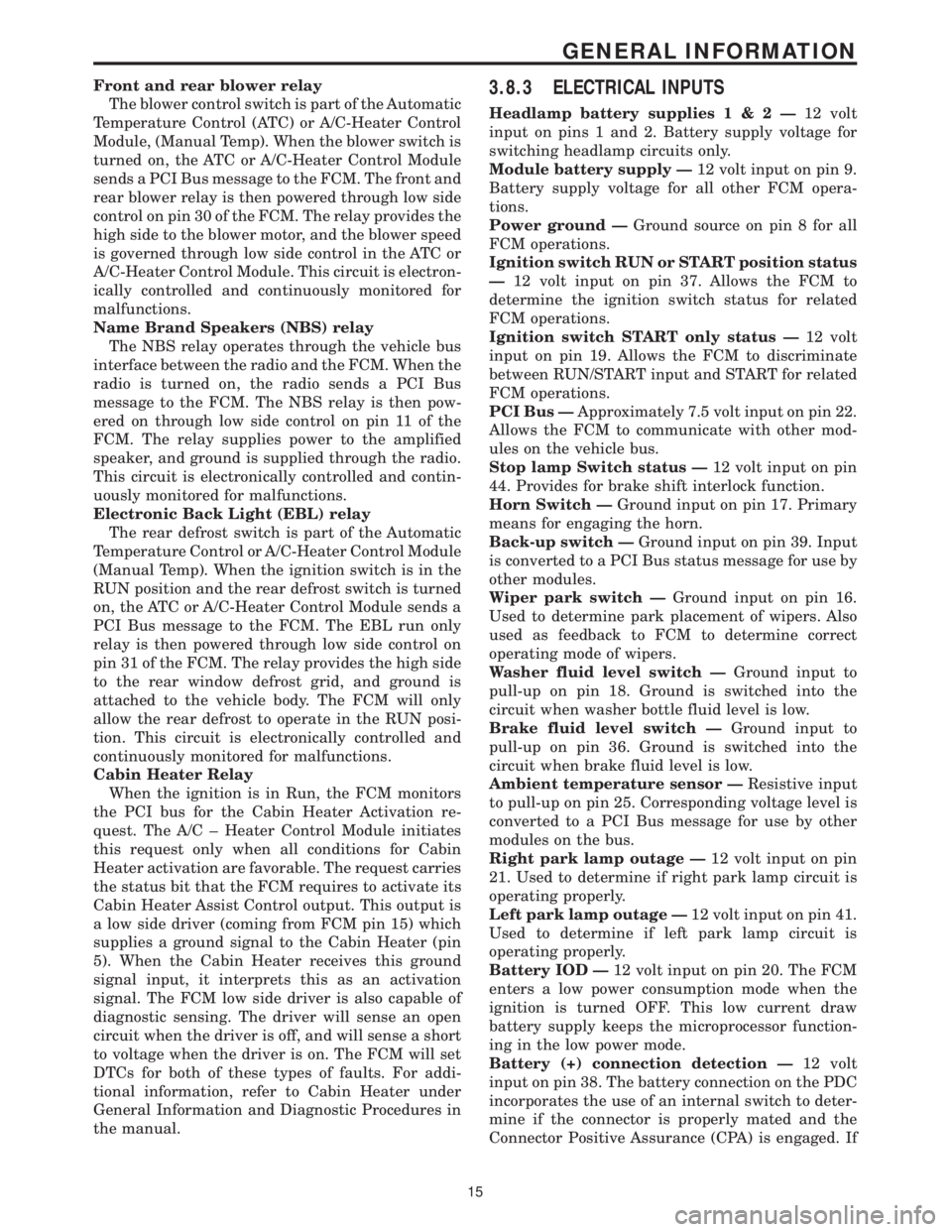
Front and rear blower relay
The blower control switch is part of the Automatic
Temperature Control (ATC) or A/C-Heater Control
Module, (Manual Temp). When the blower switch is
turned on, the ATC or A/C-Heater Control Module
sends a PCI Bus message to the FCM. The front and
rear blower relay is then powered through low side
control on pin 30 of the FCM. The relay provides the
high side to the blower motor, and the blower speed
is governed through low side control in the ATC or
A/C-Heater Control Module. This circuit is electron-
ically controlled and continuously monitored for
malfunctions.
Name Brand Speakers (NBS) relay
The NBS relay operates through the vehicle bus
interface between the radio and the FCM. When the
radio is turned on, the radio sends a PCI Bus
message to the FCM. The NBS relay is then pow-
ered on through low side control on pin 11 of the
FCM. The relay supplies power to the amplified
speaker, and ground is supplied through the radio.
This circuit is electronically controlled and contin-
uously monitored for malfunctions.
Electronic Back Light (EBL) relay
The rear defrost switch is part of the Automatic
Temperature Control or A/C-Heater Control Module
(Manual Temp). When the ignition switch is in the
RUN position and the rear defrost switch is turned
on, the ATC or A/C-Heater Control Module sends a
PCI Bus message to the FCM. The EBL run only
relay is then powered through low side control on
pin 31 of the FCM. The relay provides the high side
to the rear window defrost grid, and ground is
attached to the vehicle body. The FCM will only
allow the rear defrost to operate in the RUN posi-
tion. This circuit is electronically controlled and
continuously monitored for malfunctions.
Cabin Heater Relay
When the ignition is in Run, the FCM monitors
the PCI bus for the Cabin Heater Activation re-
quest. The A/C ± Heater Control Module initiates
this request only when all conditions for Cabin
Heater activation are favorable. The request carries
the status bit that the FCM requires to activate its
Cabin Heater Assist Control output. This output is
a low side driver (coming from FCM pin 15) which
supplies a ground signal to the Cabin Heater (pin
5). When the Cabin Heater receives this ground
signal input, it interprets this as an activation
signal. The FCM low side driver is also capable of
diagnostic sensing. The driver will sense an open
circuit when the driver is off, and will sense a short
to voltage when the driver is on. The FCM will set
DTCs for both of these types of faults. For addi-
tional information, refer to Cabin Heater under
General Information and Diagnostic Procedures in
the manual.3.8.3 ELECTRICAL INPUTS
Headlamp battery supplies1&2Ð12 volt
input on pins 1 and 2. Battery supply voltage for
switching headlamp circuits only.
Module battery supply Ð12 volt input on pin 9.
Battery supply voltage for all other FCM opera-
tions.
Power ground ÐGround source on pin 8 for all
FCM operations.
Ignition switch RUN or START position status
Ð12 volt input on pin 37. Allows the FCM to
determine the ignition switch status for related
FCM operations.
Ignition switch START only status Ð12 volt
input on pin 19. Allows the FCM to discriminate
between RUN/START input and START for related
FCM operations.
PCI Bus ÐApproximately 7.5 volt input on pin 22.
Allows the FCM to communicate with other mod-
ules on the vehicle bus.
Stop lamp Switch status Ð12 volt input on pin
44. Provides for brake shift interlock function.
Horn Switch ÐGround input on pin 17. Primary
means for engaging the horn.
Back-up switch ÐGround input on pin 39. Input
is converted to a PCI Bus status message for use by
other modules.
Wiper park switch ÐGround input on pin 16.
Used to determine park placement of wipers. Also
used as feedback to FCM to determine correct
operating mode of wipers.
Washer fluid level switch ÐGround input to
pull-up on pin 18. Ground is switched into the
circuit when washer bottle fluid level is low.
Brake fluid level switch ÐGround input to
pull-up on pin 36. Ground is switched into the
circuit when brake fluid level is low.
Ambient temperature sensor ÐResistive input
to pull-up on pin 25. Corresponding voltage level is
converted to a PCI Bus message for use by other
modules on the bus.
Right park lamp outage Ð12 volt input on pin
21. Used to determine if right park lamp circuit is
operating properly.
Left park lamp outage Ð12 volt input on pin 41.
Used to determine if left park lamp circuit is
operating properly.
Battery IOD Ð12 volt input on pin 20. The FCM
enters a low power consumption mode when the
ignition is turned OFF. This low current draw
battery supply keeps the microprocessor function-
ing in the low power mode.
Battery (+) connection detection Ð12 volt
input on pin 38. The battery connection on the PDC
incorporates the use of an internal switch to deter-
mine if the connector is properly mated and the
Connector Positive Assurance (CPA) is engaged. If
15
GENERAL INFORMATION
Page 50 of 4284

ating and the combustion air fan operation is sus-
pended for 3 seconds. Subsequently, the combustion
air fan speed is increased in two ramps within 56
seconds to nearly full load operation. After a stabi-
lization phase of 15 seconds, the combustion air fan
speed is again increased in a ramp within 50
seconds to nearly full load. After reaching full load
fuel delivery, the glow plug is deactivated and the
combustion air fan operation is increased to full
load. During the subsequent 45 seconds, as well as
in normal operation, the glow plug functions as a
flame sensor to monitor the flame condition. After
all these events, the automatically controlled heat-
ing operation starts.
In case of a no flame or a flame out condition, a
restart is automatically initiated. If the no flame
condition persists, fuel delivery is stopped and the
heater enters an error lockout mode with a run-
down of the combustion air fan. This will set one or
more DTCs in the DCHA Control's memory. If six
continuous attempts to start the heater fail due to
one or more faults in the DCHA system, the heater
enters a heater lockout mode. This will set DTC
B1813 along with any other fault(s) that the DCHA
Control identified.
3.10.3.2 HEATING
During the automatically controlled heating op-
eration, when the coolant temperature reaches
72ÉC (162ÉF), the heater will switch to a part load
operation. When the coolant temperature reaches
75ÉC (167ÉF) or if the heater runs for longer than 76
minutes the heater will switch to a control idle
period. If the coolant temperature drops to 71ÉC
(160ÉF) during a control idle period, the heater will
perform a regular starting sequence into full load
operation. A drop in coolant temperature to 65ÉC
(149ÉF) during part load operation will cause the
heater to switch to a full load operation.
3.10.3.3 DEACTIVATION
The DCHA will deactivate if the:
²engine is turned off.
²coolant temperature reaches 75ÉC (167ÉF).
²heater runs longer than 76 minutes.
²fuel tank has less than 1/8 of a tank of fuel.
²Power switch on the A/C ± Heater Control Module
is off.
²Blend Control on the A/C ± Heater Control Mod-
ule is set below 75% reheat.
When the heater is deactivated, the combustion
stops and a run-down sequence begins. During the
run-down sequence, the combustion air fan contin-
ues operation to cool down the heater. The fan is
automatically switched off after the run-down se-
quence is complete. The run-down time and thecombustion air fan speed depend on the heater
operating condition at the time of deactivation.
Run-down time is approximately 175 seconds when
deactivated in full load operation and approxi-
mately 100 seconds when deactivated in part load
operation.
3.10.4 DIAGNOSTICS
The DCHA is fully addressable with the DRBIIIt.
System tests include a Field Mode Test to activate
the DCHA for diagnostic testing purposes. The
DCHA Control will store up to three DTCs in its
memory. If the Controller detects a new fault in the
DCHA system, one that is not already stored in its
memory, it will clear the oldest of the three stored
DTCs, and it will store the new fault's DTC. If the
Controller detects a reoccurrence of a stored fault, it
will overwrite that fault's DTC with the most recent
occurrence.
3.11 INSTRUMENT CLUSTER
The Instrument Cluster receives and sends mes-
sages to other modules via the PCI bus circuit. The
indicator lamps will illuminate briefly for a bulb
check when the ignition is turned from off to run.
All of the gauges receive their information via the
PCI bus from the powertrain control module and
body control module.
The gauges and the LEDs are not individually
replaceable thereby requiring complete replace-
ment of the Instrument Cluster if a repair is neces-
sary. In the event that the Instrument Cluster loses
communication with other modules on the PCI bus,
the cluster will display ªno busº in the VF display.
The Trip/Reset button is used to switch the dis-
play from trip to total mileage. Holding the button
when the display is in the trip mode will reset the
trip mileage. This button is also used to put the
cluster in self-diagnostic mode. The odometer dis-
play uses blue-green vacuum fluorescent digital
characters.
On base vehicles, the Instrument Cluster has
three gauges: Speedometer, Fuel and Engine Cool-
ant Temperature. A red dot moves transversely
through openings in the Instrument Cluster face
(P-R-N-D-2-1) to indicate the gear selected.
With all other models, the Instrument Cluster
also includes a Tachometer and uses a vacuum-
fluorescent shift indicator.
The odometer display and door/liftgate ajar indi-
cators turn on when a door is opened to assist both
the customer and service technician to view the
odometer without turning the ignition on.
21
GENERAL INFORMATION
Page 330 of 4284

TEST ACTION APPLICABILITY
1WARNING: DO NOT OPERATE THE DCHA IN AN ENCLOSED AREA SUCH
AS A GARAGE THAT DOES NOT HAVE EXHAUST VENTILATION FACILI-
TIES. ALWAYS VENT THE DCHA's EXHAUST WHEN OPERATING THE
DCHA. FAILURE TO FOLLOW THESE INSTRUCTIONS MAY RESULT IN
PERSONAL INJURY OR DEATH.
CAUTION: DO NOT PERFORM THIS TEST UNLESS DIRECTED HERE BY
THE CABIN HEATER PRE-TEST. ALWAYS PERFORM THE CABIN HEATER
PRE-TEST PRIOR TO PERFORMING ANY OTHER CABIN HEATER TEST
FOR THE RESULT TO BE VALID.
Verify that there is more than an 1/8 of a tank of fuel in the vehicle's fuel tank.
Is there more than an 1/8 of a tank of fuel in the vehicle's fuel tank?All
Ye s®Go To 2
No®Add fuel to the vehicle's fuel tank to bring the fuel level above 1/8
of a tank.
Perform CABIN HEATER VERIFICATION TEST - VER 1.
2WARNING: DO NOT OPERATE THE DCHA IN AN ENCLOSED AREA SUCH
AS A GARAGE THAT DOES NOT HAVE EXHAUST VENTILATION FACILI-
TIES. ALWAYS VENT THE DCHA's EXHAUST WHEN OPERATING THE
DCHA. FAILURE TO FOLLOW THESE INSTRUCTIONS MAY RESULT IN
PERSONAL INJURY OR DEATH.
WARNING: ALLOW THE DCHA ASSEMBLY TO COOL BEFORE PERFORM-
ING A COMPONENT INSPECTION/REPAIR/REPLACEMENT. FAILURE TO
FOLLOW THESE INSTRUCTIONS MAY RESULT IN PERSONAL INJURY.
Turn the ignition on.
CAUTION: Do not actuate the Dosing Pump more than two times. Doing so
will put excess fuel in the DCHA Heater Module and cause smoke to emit
from the DCHA exhaust pipe when heater activation occurs.
With the DRBIIItin Actuators, select Dosing Pump. Listen for the pump to run. A
clicking noise should be heard coming from the pump.
Press Page Back and select No to stop the Dosing Pump actuation.
Does the Dosing Pump run when actuated?All
Ye s®Go To 3
No®Replace the Dosing Pump in accordance with the Service Infor-
mation.
Perform CABIN HEATER VERIFICATION TEST - VER 1.
301
CABIN HEATER
B1800 NO START ÐContinued
Page 1017 of 4284
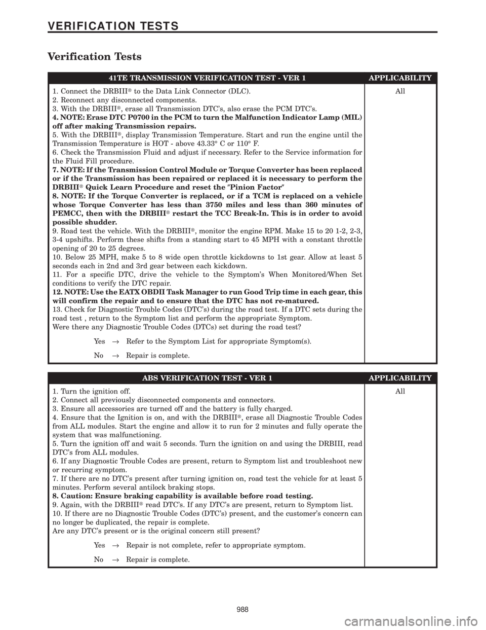
Verification Tests
41TE TRANSMISSION VERIFICATION TEST - VER 1 APPLICABILITY
1. Connect the DRBIIItto the Data Link Connector (DLC).
2. Reconnect any disconnected components.
3. With the DRBIIIt, erase all Transmission DTC's, also erase the PCM DTC's.
4. NOTE: Erase DTC P0700 in the PCM to turn the Malfunction Indicator Lamp (MIL)
off after making Transmission repairs.
5. With the DRBIIIt, display Transmission Temperature. Start and run the engine until the
Transmission Temperature is HOT - above 43.33É C or 110É F.
6. Check the Transmission Fluid and adjust if necessary. Refer to the Service information for
the Fluid Fill procedure.
7. NOTE: If the Transmission Control Module or Torque Converter has been replaced
or if the Transmission has been repaired or replaced it is necessary to perform the
DRBIIItQuick Learn Procedure and reset the(Pinion Factor(
8. NOTE: If the Torque Converter is replaced, or if a TCM is replaced on a vehicle
whose Torque Converter has less than 3750 miles and less than 360 minutes of
PEMCC, then with the DRBIIItrestart the TCC Break-In. This is in order to avoid
possible shudder.
9. Road test the vehicle. With the DRBIIIt, monitor the engine RPM. Make 15 to 20 1-2, 2-3,
3-4 upshifts. Perform these shifts from a standing start to 45 MPH with a constant throttle
opening of 20 to 25 degrees.
10. Below 25 MPH, make 5 to 8 wide open throttle kickdowns to 1st gear. Allow at least 5
seconds each in 2nd and 3rd gear between each kickdown.
11. For a specific DTC, drive the vehicle to the Symptom's When Monitored/When Set
conditions to verify the DTC repair.
12. NOTE: Use the EATX OBDII Task Manager to run Good Trip time in each gear, this
will confirm the repair and to ensure that the DTC has not re-matured.
13. Check for Diagnostic Trouble Codes (DTC's) during the road test. If a DTC sets during the
road test , return to the Symptom list and perform the appropriate Symptom.
Were there any Diagnostic Trouble Codes (DTCs) set during the road test?All
Ye s®Refer to the Symptom List for appropriate Symptom(s).
No®Repair is complete.
ABS VERIFICATION TEST - VER 1 APPLICABILITY
1. Turn the ignition off.
2. Connect all previously disconnected components and connectors.
3. Ensure all accessories are turned off and the battery is fully charged.
4. Ensure that the Ignition is on, and with the DRBIIIt, erase all Diagnostic Trouble Codes
from ALL modules. Start the engine and allow it to run for 2 minutes and fully operate the
system that was malfunctioning.
5. Turn the ignition off and wait 5 seconds. Turn the ignition on and using the DRBIII, read
DTC's from ALL modules.
6. If any Diagnostic Trouble Codes are present, return to Symptom list and troubleshoot new
or recurring symptom.
7. If there are no DTC's present after turning ignition on, road test the vehicle for at least 5
minutes. Perform several antilock braking stops.
8. Caution: Ensure braking capability is available before road testing.
9. Again, with the DRBIIItread DTC's. If any DTC's are present, return to Symptom list.
10. If there are no Diagnostic Trouble Codes (DTC's) present, and the customer's concern can
no longer be duplicated, the repair is complete.
Are any DTC's present or is the original concern still present?All
Ye s®Repair is not complete, refer to appropriate symptom.
No®Repair is complete.
988
VERIFICATION TESTS
Page 1022 of 4284
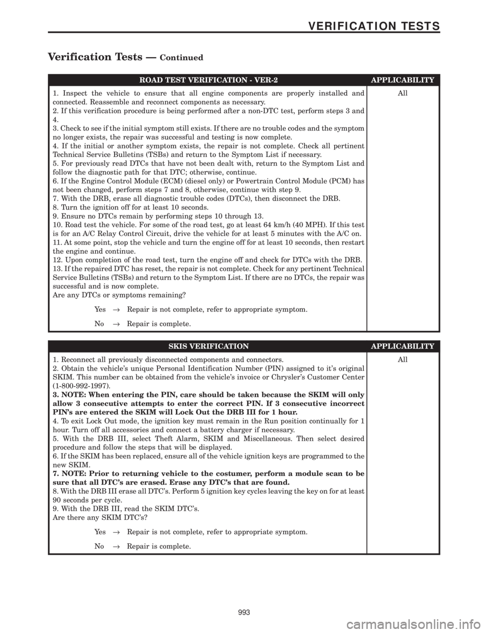
ROAD TEST VERIFICATION - VER-2 APPLICABILITY
1. Inspect the vehicle to ensure that all engine components are properly installed and
connected. Reassemble and reconnect components as necessary.
2. If this verification procedure is being performed after a non-DTC test, perform steps 3 and
4.
3. Check to see if the initial symptom still exists. If there are no trouble codes and the symptom
no longer exists, the repair was successful and testing is now complete.
4. If the initial or another symptom exists, the repair is not complete. Check all pertinent
Technical Service Bulletins (TSBs) and return to the Symptom List if necessary.
5. For previously read DTCs that have not been dealt with, return to the Symptom List and
follow the diagnostic path for that DTC; otherwise, continue.
6. If the Engine Control Module (ECM) (diesel only) or Powertrain Control Module (PCM) has
not been changed, perform steps 7 and 8, otherwise, continue with step 9.
7. With the DRB, erase all diagnostic trouble codes (DTCs), then disconnect the DRB.
8. Turn the ignition off for at least 10 seconds.
9. Ensure no DTCs remain by performing steps 10 through 13.
10. Road test the vehicle. For some of the road test, go at least 64 km/h (40 MPH). If this test
is for an A/C Relay Control Circuit, drive the vehicle for at least 5 minutes with the A/C on.
11. At some point, stop the vehicle and turn the engine off for at least 10 seconds, then restart
the engine and continue.
12. Upon completion of the road test, turn the engine off and check for DTCs with the DRB.
13. If the repaired DTC has reset, the repair is not complete. Check for any pertinent Technical
Service Bulletins (TSBs) and return to the Symptom List. If there are no DTCs, the repair was
successful and is now complete.
Are any DTCs or symptoms remaining?All
Ye s®Repair is not complete, refer to appropriate symptom.
No®Repair is complete.
SKIS VERIFICATION APPLICABILITY
1. Reconnect all previously disconnected components and connectors.
2. Obtain the vehicle's unique Personal Identification Number (PIN) assigned to it's original
SKIM. This number can be obtained from the vehicle's invoice or Chrysler's Customer Center
(1-800-992-1997).
3. NOTE: When entering the PIN, care should be taken because the SKIM will only
allow 3 consecutive attempts to enter the correct PIN. If 3 consecutive incorrect
PIN's are entered the SKIM will Lock Out the DRB III for 1 hour.
4. To exit Lock Out mode, the ignition key must remain in the Run position continually for 1
hour. Turn off all accessories and connect a battery charger if necessary.
5. With the DRB III, select Theft Alarm, SKIM and Miscellaneous. Then select desired
procedure and follow the steps that will be displayed.
6. If the SKIM has been replaced, ensure all of the vehicle ignition keys are programmed to the
new SKIM.
7. NOTE: Prior to returning vehicle to the costumer, perform a module scan to be
sure that all DTC's are erased. Erase any DTC's that are found.
8. With the DRB III erase all DTC's. Perform 5 ignition key cycles leaving the key on for at least
90 seconds per cycle.
9. With the DRB III, read the SKIM DTC's.
Are there any SKIM DTC's?All
Ye s®Repair is not complete, refer to appropriate symptom.
No®Repair is complete.
993
VERIFICATION TESTS
Verification Tests ÐContinued
Page 1070 of 4284
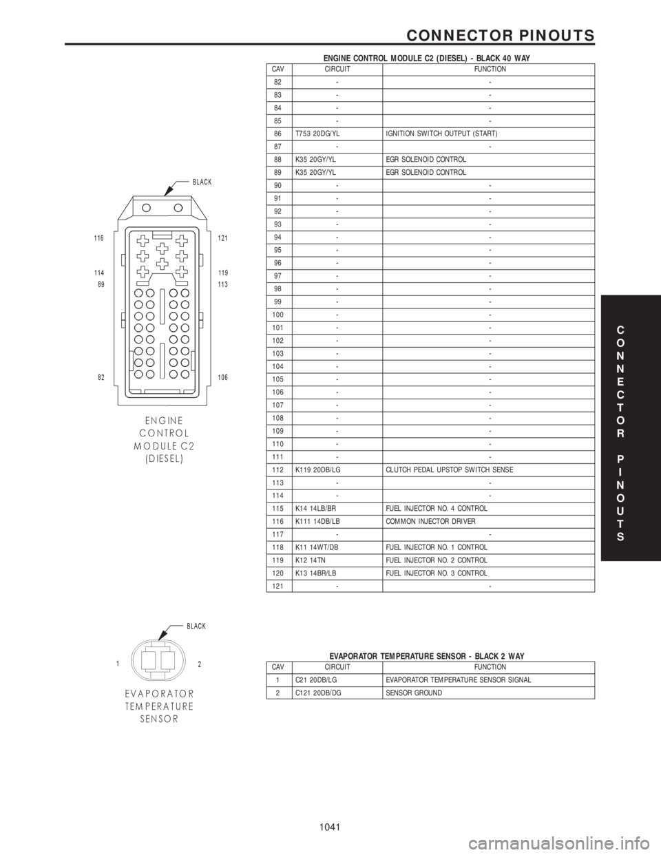
ENGINE CONTROL MODULE C2 (DIESEL) - BLACK 40 WAYCAV CIRCUIT FUNCTION
82 - -
83 - -
84 - -
85 - -
86 T753 20DG/YL IGNITION SWITCH OUTPUT (START)
87 - -
88 K35 20GY/YL EGR SOLENOID CONTROL
89 K35 20GY/YL EGR SOLENOID CONTROL
90 - -
91 - -
92 - -
93 - -
94 - -
95 - -
96 - -
97 - -
98 - -
99 - -
100 - -
101 - -
102 - -
103 - -
104 - -
105 - -
106 - -
107 - -
108 - -
109 - -
110 - -
111 - -
112 K119 20DB/LG CLUTCH PEDAL UPSTOP SWITCH SENSE
113 - -
114 - -
115 K14 14LB/BR FUEL INJECTOR NO. 4 CONTROL
116 K111 14DB/LB COMMON INJECTOR DRIVER
117 - -
118 K11 14WT/DB FUEL INJECTOR NO. 1 CONTROL
119 K12 14TN FUEL INJECTOR NO. 2 CONTROL
120 K13 14BR/LB FUEL INJECTOR NO. 3 CONTROL
121 - -
EVAPORATOR TEMPERATURE SENSOR - BLACK 2 WAYCAV CIRCUIT FUNCTION
1 C21 20DB/LG EVAPORATOR TEMPERATURE SENSOR SIGNAL
2 C121 20DB/DG SENSOR GROUND
C
O
N
N
E
C
T
O
R
P
I
N
O
U
T
S
1041
CONNECTOR PINOUTS