2001 CHRYSLER VOYAGER air conditioning
[x] Cancel search: air conditioningPage 45 of 4284
the CPA is not properly engaged, a voltage on pin 38
will be interpreted as an unseated connector and a
fault will set.
Flash programming voltage Ð20 volt input on
pin 42. When a DRBIIItis connected and the
proper flash reprogramming sequence is selected,
the 20 volt signal will be applied through pin 42.
3.9 HEATING & A/C
3.9.1 AUTOMATIC TEMPERATURE
CONTROL (ATC)
3.9.1.1 CABIN HEATER
For vehicles equipped with a diesel engine, a
Cabin Heater is used in conjunction with the HVAC
system. The Cabin Heater is designed to supply the
vehicle's occupants with heat prior to the engine
reaching operating temperature. For additional in-
formation on this system, refer to Cabin Heater
under General Information and Diagnostic Proce-
dures in this manual.
3.9.1.2 SYSTEM OPERATION
The Automatic Temperature Control (ATC) sys-
tem provides fully adjustable three zone climate
control; Driver front zone, Passenger Front zone
and Rear zone. The following is a list of ATC
controls and features:
± a POWER button which allows the operator to
turn the system completely off.
± AUTO HIGH/LOW switch allows the operator
to select what rate (fan speed) the system will
provide the selected comfort level.
± DRIVER, REAR and PASSENGER rocker
switches to select desired temperature for each
zone.
± Recirculation button allows cooling air to be
recirculated which maximizes cooling ability.
± A/C select button allows the operator to turn
the A/C compressor off.
± Defroster button allows the operator to turn on
the defroster independently during automatic
control.
± Fan control rotary switch for selecting fan
speed.
± Mode rotary switch for selecting heating/
cooling direction.
± REAR SYSTEM rotary switch for activating
the Rear ATC Switch allowing intermediate
passenger control over rear climate control.
3.9.1.3 BLOWER MOTOR OPERATION
The Automatic Temperature Control (ATC) front
and rear blower control provides continuously vari-
able control of air flow rate to meet occupant
comfort requirements. Pulse width modulation of
the blower motor power allows the front and rear
blower to operate at any speed from off to full speed.
When front or rear blower operation is required, the
ATC sends a PCI Bus message to the Front Control
Module (FCM) requesting blower relay ON. The
FCM provides a ground for the front and rear
blower motor relay coils, activating both relays. The
front and rear blower relays provide 12 volts to
their respective blower motor power modules. Each
module provides a 12 volt blower motor control
signal to the ATC. The ATC provides a pulse width
modulated (duty-cycle) ground signal to this circuit
based on climate requirements. The higher voltage
on the signal circuit (less duty-cycle ground) the
lower the blower speed request. The lower voltage
on the signal circuit (more duty-cycle ground) the
higher the blower speed request.
3.9.1.4 INFRARED SENSORS
The ATC system uses infrared (I/R) sensors to
monitor and control oocupant comfort levels. This
sensing system replaces interior air temperature
and solar sensors which required complex control
programs to maintain occupant comfort levels. The
front I/R sensor is located in the instrument panel
center bezel outlet. The rear I/R sensor is located in
the rear overhead mounted ATC switch.
3.9.1.5 REAR ATC SWITCH
The rear ATC switch is mounted in the headliner.
The switch contains a rotary adjustment for fan
speed, a rotary adjustment for mode selection, a
push button switch for temperature selection and a
digital display of the selected temperature.
3.9.1.6 COOLDOWN TESTING
The ATC provides a feature referred to as a
Cooldown Test. This test is initiated using the
DRBIIItand is designed to check the performance
of the air conditioning system. The ATC will not
perform this test if the ambient air temperature is
below 12ÉC (53ÉF). During the test, the ATC com-
pares the ambient air temperature to the evapora-
tor temperature sensor. To pass the cooldown test,
the evap temperature sensor must drop -6ÉC (20ÉF)
below ambient temperature within 2 minutes of
start of test. At the completion of the cooldown test
the DRBIIItwill display one of the following mes-
sages indicating test outcome:
± Cooldown Test Passed
± Cooldown Test Failed
16
GENERAL INFORMATION
Page 46 of 4284
± Evap Temp Sensor Shorted
± Evap Temp Sensor Open
± A/C Pressure Too Low
± A/C Pressure Too High
± Invalid Conditions for Cooldown Test, Evap
Temperature Too Low
If a message other than Cooldown Test Passed
occurs, refer to the appropriate symptom for diag-
nosis.
3.9.1.7 ACTIVE AND STORED TROUBLE
CODES
The Automatic Temperature Control (ATC) is
capable of storing Active and Stored trouble codes.
Active codes indicate a current fault in the system.
Stored codes indicate that a problem has occurred
in the system, however is not currently present.
Active codes cannot be erased until the problem
causing the code has been repaired. At this time the
Active code is converted to a Stored code, which can
be erased using the DRBIIIt.
3.9.2 MANUAL TEMPERATURE CONTROL
3.9.2.1 SYSTEM AVAILABILITY
Depending on the model, either a Single-Zone Air
Conditioning System or a Dual-Zone Air Condition-
ing System is currently available in these vehicles.
3.9.2.2 CABIN HEATER
For Vehicles equipped with a diesel engine, a
Cabin Heater is used in conjunction with the HVAC
system. The Cabin Heater is designed to supply the
vehicle's occupants with heat prior to the engine
reaching operating temperature. For additional in-
formation on this system, refer to Cabin Heater
under General Information and Diagnostic Proce-
dures in this manual.
3.9.2.3 ZONE CONTROL ± SINGLE-ZONE
The Single-Zone Air Conditioning System main-
tains incoming air temperature, airflow, fan speed,
and fresh air intake for the entire vehicle from the
instrument panel mounted A/C ± Heater Control
Module. The full range of temperature that the
system can produce in any mode for the entire
vehicle is available by positioning the blend control
to the desired range.
3.9.2.4 ZONE CONTROL ± DUAL-ZONE
The Dual-Zone Air Conditioning System main-
tains incoming air temperature, airflow, fan speed,
and fresh air intake for the entire vehicle from the
instrument panel mounted A/C ± Heater ControlModule. In addition, this system provides com-
pletely independent side-to-side control of incoming
air temperature. The full range of temperature that
the system can produce in any mode is available on
either side of the vehicle by positioning the inde-
pendent driver and passenger blend controls to the
desired range.
3.9.2.5 AIR DISTRIBUTION
The HVAC unit has five fully adjustable instru-
ment panel outlets. Side-window demister outlets
in the instrument panel eliminate door ducts and
door-to-instrument panel seals. A single, central
mounted outlet delivers air for defrosting the wind-
shield. Air exhausters allow air entering at the
front of the vehicle to flow out the back to the rear
occupants. Mid-cabin comfort control directs only
cooling air flow to the intermediate seat occupants
through outlets at the rear of each front door trim
panel. Air is supplied to these outlets from the
instrument panel through ducts in the doors that
use molded seals at the instrument panel to prevent
air leakage. Wide outlets under the front seats with
directional dividers distribute heated air across the
floor to the intermediate seat occupants. Ducts in
the center of the vehicle under the carpet deliver air
from the HVAC unit to these outlets. Models
equipped with Dual-Zone A/C systems also include
a dust and odor air filter installed in the HAVC
housing.
3.9.2.6 DOOR ACTUATORS
The electric door actuators are a two-wire design.
Each door actuator uses a similar connector wired
directly to the A/C ± Heater Control Module. Single-
Zone systems have one blend door actuator, one
mode door actuator, and one recirculation door
actuator. Dual-Zone systems have two blend door
actuators, one mode door actuator, and one recircu-
lation door actuator. All of the door actuators are
accessible from the vehicle's interior.
3.9.2.7 DOOR ACTUATOR CONTROL
The A/C ± Heater Control Module knows the
number of operating actuator revolutions required
for full door travel as well as the number of actuator
commutator pulses per revolution. Using these pa-
rameters, the A/C ± Heater Control Module runs
the actuator for the number of commutator pulses
that correspond to the desired door position. To
maintain accuracy, the system recalibrates itself
periodically at known zero and full travel condi-
tions.
17
GENERAL INFORMATION
Page 59 of 4284
WARNING: BEFORE ROAD TESTING A
VEHICLE, BE SURE THAT ALL
COMPONENTS ARE REASSEMBLED.
DURING THE TEST DRIVE, DO NOT TRY TO
READ THE DRBIIITSCREEN WHILE IN
MOTION. DO NOT HANG THE DRBIIITFROM
THE REAR VIEW MIRROR OR OPERATE IT
YOURSELF. HAVE AN ASSISTANT
AVAILABLE TO OPERATE THE DRBIIIT.
5.0 REQUIRED TOOLS AND
EQUIPMENT
DRBIIIt(diagnostic read-out box)
Jumper wires
Ohmmeter
Voltmeter
Sentry Key Tester
Test Light
8310 Airbag System Load Tool
8443 SRS Airbag System Load Tool
Diagnostic Junction Port Tester 8339
6.0 GLOSSARY OF TERMS
ABSantilock brake system
ACMairbag control module
AECMairbag electronic control module
(ACM)
ASDMairbag system diagnostic module
(ACM)
AT Cautomatic temperature control
BCMbody control module
CABcontroller antilock brake
CMTCcompass/mini-trip computer
CPAconnector positive assurance
DABdriver airbag
DCHAdiesel cabin heater assist
(cabin heater)
DLCdata link connector
DTCdiagnostic trouble code
DRdriver
EBLelectric back lite (rear window de-
fogger)ECMEngine control module
EVICelectronic vehicle information center
FCMfront control module
GCCGulf Coast Countries
HVACheater ventilation, air conditioning
IPMintelligent power module
LDUlower drive unit
LHDLeft Hand Drive
MICmechanical instrument cluster
MTCmanual temperature control
MSMMmemory seat/mirror module
OBDon board diagnostics
ODOodometer
ORCoccupant restraint controller
PA Bpassenger airbag
PASSpassenger
PCIProgrammable Communication In-
terface (vehicle communication bus)
PCMpowertrain control module
PDCpower distribution center
PLGpower liftgate
PLGMpower liftgate module
PSDpower sliding door
PSDMpower sliding door module
PWMpulse width modulated
RHDRight Hand Drive
RKEremote keyless entry
SABseat airbag
SBTseat belt tensioner
SIACMside impact airbag control module
SKIMsentry key immobilizer module
SKISsentry key immobilizer system
SQUIBalso called initiator (located inside
airbag)
SRSsupplemental restraint system
TCMtransmission control module
VFDvacuum fluorescent display
VTSSvehicle theft security system
30
GENERAL INFORMATION
Page 1227 of 4284
4.3 WARNINGS AND CAUTIONS
4.3.1 ROAD TEST WARNINGS
Some complaints will require a test drive as part
of the repair verification procedure. The purpose of
the test drive is to try to duplicate the diagnostic
code or symptom condition.
CAUTION: BEFORE ROAD TESTING A
VEHICLE, BE SURE THAT ALL
COMPONENTS ARE REASSEMBLED. DUR-
ING THE TEST DRIVE, DO NOT HANG THE
DRBIIITFROM THE REAR VIEW MIRROR. DO
NOT ATTEMPT TO READ THE DRBIIITWHILE
DRIVING. HAVE AN ASSISTANT AVAILABLE
TO OPERATE THE DRBIIIT.
4.3.2 VEHICLE DAMAGE CAUTIONS
Before disconnecting any control module, make
sure the ignition is off. Failure to do so could
damage the module. When testing voltage or circuit
integrity at any control module, use the terminal
side (not the wire end) of the harness connector. Do
not probe through the insulation; this will damage
it and eventually cause it to fail because of corro-
sion.
Be careful when performing electrical test so as to
prevent accidental shorting of terminals. Such a
mistake can damage fuses or components. Also, a
second code could be set, making diagnosis of the
original problem more difficult.
5.0 REQUIRED TOOLS AND
EQUIPMENT
DRBIIIt(diagnostic read-out box) scan tool
vacuum gauge
ammeter
ohmmeter
jumper wires and probes
oscilloscope
6.0 GLOSSARY OF TERMS
A/Cair conditioning
APPaccelerator pedal position (sensor)
backfire,
popbackfuel ignites in either the intake or
the exhaust system
BCMbody control module
BPboost pressure (sensor)CKPcrankshaft position (sensor)
CMPcamshaft position (sensor)
cuts out,
missesa steady pulsation or the inability of
the engine to maintain a consistent
rpm
DLCdata link connector
detona-
tion,
spark
knocka mild to severe ping, especially un-
der loaded engine conditions
ECMengine control module
ECTengine coolant temperature (sensor)
EGRexhaust gas recirculation
(solenoid/valve)
hard
startthe engine takes longer than usual
to start, even though it is able to
crank at normal speed.
IATintake air temperature (sensor)
IPMintelligent power module
lack of
power,
sluggishthe engine power output has been
reduced
MAFmass air flow (sensor)
MILmalfunction indicator lamp
msmillisecond(s)
PDCpower distribution center
poor fuel
economythere is significantly less fuel mile-
age than other vehicles of the same
design and configuration
runs
rough/
unstable
idlethe engine runs unevenly at idle
causing the engine to shake if it is
severe enough
S/Cspeed control
SKIMsentry key immobilizer module
SKISsentry key immobilizer system
start and
stallThe engine starts but immediately
dies (stalls)
surgeengine rpm fluctuation without cor-
responding change in accelerator
pedal position
SRCsignal range check
WIFwater in fuel (sensor)
VSSvehicle speed sensor
8
GENERAL INFORMATION
Page 1468 of 4284
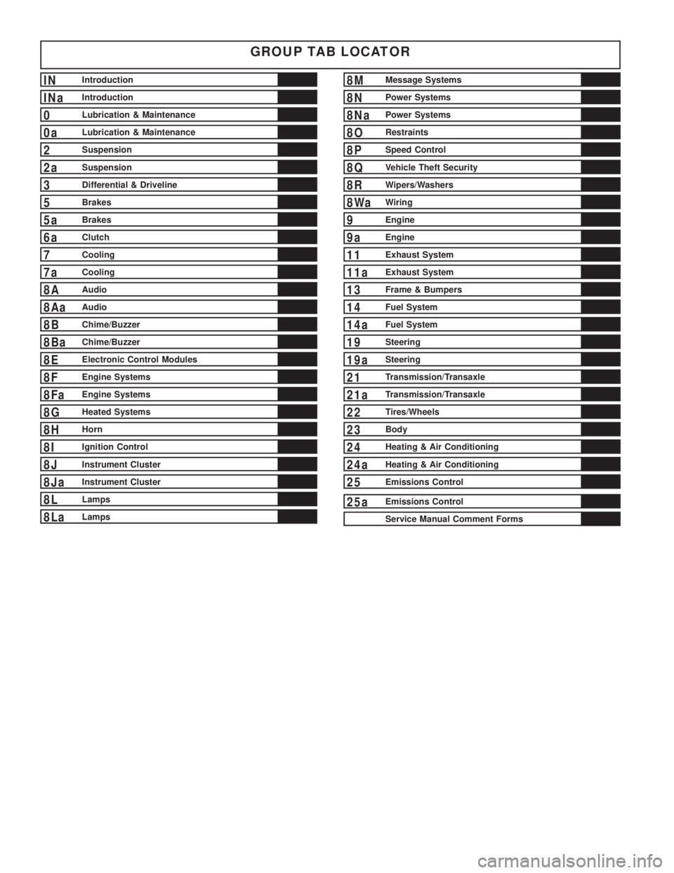
GROUP TAB LOCATOR
INIntroduction
INaIntroduction
0Lubrication & Maintenance
0aLubrication & Maintenance
2Suspension
2aSuspension
3Differential & Driveline
5Brakes
5aBrakes
6aClutch
7Cooling
7aCooling
8AAudio
8AaAudio
8BChime/Buzzer
8BaChime/Buzzer
8EElectronic Control Modules
8FEngine Systems
8FaEngine Systems
8GHeated Systems
8HHorn
8IIgnition Control
8JInstrument Cluster
8JaInstrument Cluster
8LLamps
8LaLamps
8MMessage Systems
8NPower Systems
8NaPower Systems
8ORestraints
8PSpeed Control
8QVehicle Theft Security
8RWipers/Washers
8WaWiring
9Engine
9aEngine
11Exhaust System
11aExhaust System
13Frame & Bumpers
14Fuel System
14aFuel System
19Steering
19aSteering
21Transmission/Transaxle
21aTransmission/Transaxle
22Tires/Wheels
23Body
24Heating & Air Conditioning
24aHeating & Air Conditioning
25Emissions Control
25aEmissions Control
Service Manual Comment Forms
Page 1707 of 4284
CAUTION: A seal on the rear of the master cylinder
is used to create the seal for holding vacuum in the
power brake vacuum booster. The vacuum seal on
the master cylinder MUST be replaced whenever the
master cylinder is removed from the power brake
vacuum booster.
(12) Remove vacuum seal located on the mounting
flange of the master cylinder. The vacuum seal is
removed from master cylinder bycarefullypulling it
off the rear of master cylinder.Do not attempt to
pry the seal off the master cylinder by inserting
a sharp tool between seal and master cylinder
casting.
INSTALLATION
CAUTION: Different types of master cylinders are
used on this vehicle depending on brake options. If
a new master cylinder is being installed, be sure it
is the correct master cylinder for the type of brake
system the vehicle is equipped with.
CAUTION: When replacing the master cylinder on a
vehicle, a NEW vacuum seal MUST be installed on
the master cylinder.
(1) Install a NEW vacuum seal on master cylinder
making sure seal fits squarely in groove of master
cylinder casting.
(2) Position master cylinder on studs of power
brake booster, aligning booster push rod with master
cylinder piston.
(3) Install the two master cylinder mounting nuts
(Fig. 2). Tighten both mounting nuts to a torque of
25 N´m (225 in. lbs.).
CAUTION: When tightening the primary and sec-
ondary brake tube nuts at master cylinder, be sure
brake tubes do not contact any other components
within the vehicle and that there is slack in the flex-
ible sections of the tubes. This is required due to
the movement between the ABS ICU and the master
cylinder while the vehicle is in motion.
(4) Connect primary and secondary brake tubes to
master cylinder primary and secondary ports (Fig. 2).
Brake tubes must be held securely when tightened to
control orientation of flex section. Tighten tube nuts
to a torque of 17 N´m (145 in. lbs.).
(5) Install wiring harness connector to brake fluid
level switch mounted in brake fluid reservoir (Fig. 1).
(6) Install battery, clamp and nut.
(7) Install battery shield.
(8) Connect positive battery terminal.
(9) Connect negative battery terminal.(10) Fill master cylinder with clean, fresh Mopart
Brake Fluid or equivalent.
(11) Road test vehicle to ensure proper operation of
brakes.
PEDAL TORQUE SHAFT
REMOVAL
(1) Remove the instrument panel. (Refer to 23 -
BODY/INSTRUMENT PANEL/INSTRUMENT
PANEL ASSEMBLY - REMOVAL)
(2) Remove the HVAC housing. (Refer to 24 -
HEATING & AIR CONDITIONING/DISTRIBUTION/
HVAC HOUSING - REMOVAL)
(3) Remove the retaining clip at the torque shaft
end of the brake pedal-to-torque shaft link. Remove
the link from the torque shaft. Discard the retaining
clip. It is not to be reused. Replace with a new clip
when reassembled.
(4) Locate the booster input rod-to-brake pedal
torque shaft connection and remove the retaining clip
(Fig. 3). Discard the retaining clip. It is not to be
reused. Replace with a new clip when reassembled.
(5) Remove the four (4) brake booster retaining
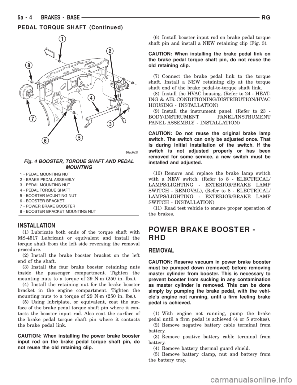
nuts from inside the passenger compartment (Fig. 4).
(6) Remove the retaining nut from the brake
booster bracket located above the booster in the
engine compartment (Fig. 4).
(7) Remove the power brake booster bracket.
(8) Rotate the pedal torque shaft and remove it out
the left side of the vehicle.
Fig. 3 POWER BRAKE BOOSTER BRACKET
1 - BOOSTER BRACKET
2 - PEDAL TORQUE SHAFT
3 - RETAINING CLIP
4 - BOOSTER MOUNTING NUTS
RGBRAKES - BASE5a-3
MASTER CYLINDER - RHD (Continued)
Page 1708 of 4284
INSTALLATION
(1) Lubricate both ends of the torque shaft with
MS-4517 Lubricant or equivalent and install the
torque shaft from the left side reversing the removal
procedure.
(2) Install the brake booster bracket on the left
end of the shaft.
(3) Install the four brake booster retaining nuts
inside the passenger compartment. Tighten the
mounting nuts to a torque of 29 N´m (250 in. lbs.).
(4) Install the retaining nut for the brake booster
bracket in the engine compartment. Tighten the
mounting nuts to a torque of 29 N´m (250 in. lbs.).
(5) Using lubriplate, or equivalent, coat the sur-
face of the brake pedal torque shaft pin where it con-
tacts the booster input rod. Also coat the surface of
the brake pedal torque shaft pin where it contacts
the brake pedal link.
CAUTION: When installing the power brake booster
input rod on the brake pedal torque shaft pin, do
not reuse the old retaining clip.(6) Install booster input rod on brake pedal torque
shaft pin and install a NEW retaining clip (Fig. 3).
CAUTION: When installing the brake pedal link on
the brake pedal torque shaft pin, do not reuse the
old retaining clip.
(7) Connect the brake pedal link to the torque
shaft. Install a NEW retaining clip at the torque
shaft end of the brake pedal-to-torque shaft link.
(8) Install the HVAC housing. (Refer to 24 - HEAT-
ING & AIR CONDITIONING/DISTRIBUTION/HVAC
HOUSING - INSTALLATION)
(9) Install the instrument panel. (Refer to 23 -
BODY/INSTRUMENT PANEL/INSTRUMENT
PANEL ASSEMBLY - INSTALLATION)
CAUTION: Do not reuse the original brake lamp
switch. The switch can only be adjusted once. That
is during initial installation of the switch. If the
switch is not adjusted properly or has been
removed for some service, a new switch must be
installed and adjusted.
(10) Remove and replace the brake lamp switch
with a NEW switch. (Refer to 8 - ELECTRICAL/
LAMPS/LIGHTING - EXTERIOR/BRAKE LAMP
SWITCH - REMOVAL), (Refer to 8 - ELECTRICAL/
LAMPS/LIGHTING - EXTERIOR/BRAKE LAMP
SWITCH - INSTALLATION)
(11) Road test vehicle to ensure proper operation of
the brakes.POWER BRAKE BOOSTER -
RHD
REMOVAL
CAUTION: Reserve vacuum in power brake booster
must be pumped down (removed) before removing
master cylinder from booster. This is necessary to
prevent booster from sucking in any contamination
as master cylinder is removed. This can be done
simply by pumping the brake pedal, with the vehi-
cle's engine not running, until a firm feeling brake
pedal is achieved.
(1) With engine not running, pump the brake
pedal until a firm pedal is achieved (4 or 5 strokes).
(2) Remove negative battery cable terminal from
battery.
(3) Remove positive battery cable terminal from
battery.
(4) Remove battery thermal guard shield.
(5) Remove battery clamp, nut and battery from
the battery tray.
Fig. 4 BOOSTER, TORQUE SHAFT AND PEDAL
MOUNTING
1 - PEDAL MOUNTING NUT
2 - BRAKE PEDAL ASSEMBLY
3 - PEDAL MOUNTING NUT
4 - PEDAL TORQUE SHAFT
5 - BOOSTER MOUNTING NUT
6 - BOOSTER BRACKET
7 - POWER BRAKE BOOSTER
8 - BOOSTER BRACKET MOUNTING NUT
5a - 4 BRAKES - BASERG
PEDAL TORQUE SHAFT (Continued)
Page 1731 of 4284
(4) Install clutch release bearing/lever assembly
into position by sliding bearing onto input bearing
retainer, and using moderate hand pressure to seat
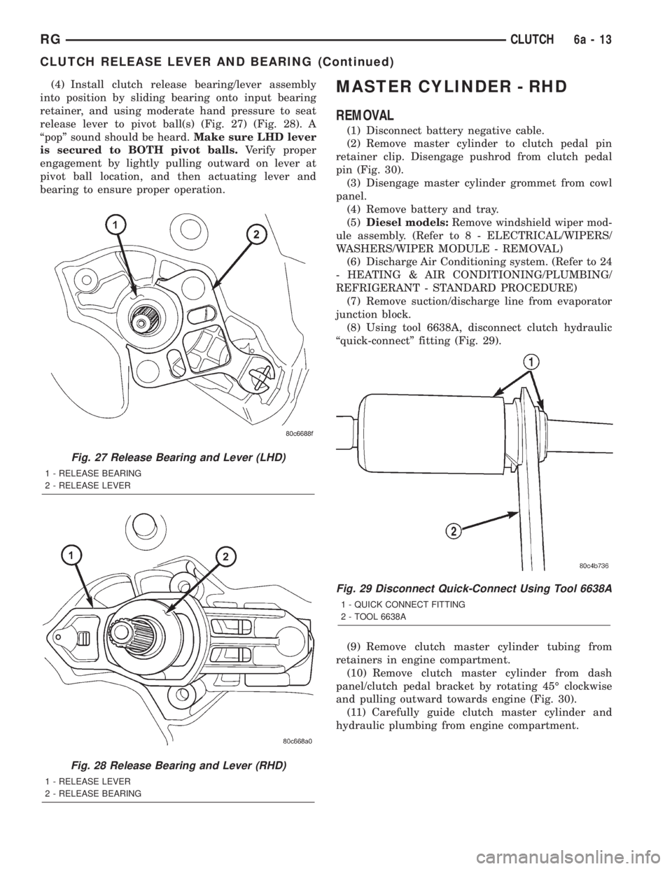
release lever to pivot ball(s) (Fig. 27) (Fig. 28). A
ªpopº sound should be heard.Make sure LHD lever
is secured to BOTH pivot balls.Verify proper
engagement by lightly pulling outward on lever at
pivot ball location, and then actuating lever and
bearing to ensure proper operation.MASTER CYLINDER - RHD
REMOVAL
(1) Disconnect battery negative cable.
(2) Remove master cylinder to clutch pedal pin
retainer clip. Disengage pushrod from clutch pedal
pin (Fig. 30).
(3) Disengage master cylinder grommet from cowl
panel.
(4) Remove battery and tray.
(5)Diesel models:Remove windshield wiper mod-
ule assembly. (Refer to 8 - ELECTRICAL/WIPERS/
WASHERS/WIPER MODULE - REMOVAL)
(6) Discharge Air Conditioning system. (Refer to 24
- HEATING & AIR CONDITIONING/PLUMBING/
REFRIGERANT - STANDARD PROCEDURE)
(7) Remove suction/discharge line from evaporator
junction block.
(8) Using tool 6638A, disconnect clutch hydraulic
ªquick-connectº fitting (Fig. 29).
(9) Remove clutch master cylinder tubing from
retainers in engine compartment.
(10) Remove clutch master cylinder from dash
panel/clutch pedal bracket by rotating 45É clockwise
and pulling outward towards engine (Fig. 30).
(11) Carefully guide clutch master cylinder and
hydraulic plumbing from engine compartment.
Fig. 27 Release Bearing and Lever (LHD)
1 - RELEASE BEARING
2 - RELEASE LEVER
Fig. 28 Release Bearing and Lever (RHD)
1 - RELEASE LEVER
2 - RELEASE BEARING
Fig. 29 Disconnect Quick-Connect Using Tool 6638A
1 - QUICK CONNECT FITTING
2 - TOOL 6638A
RGCLUTCH6a-13
CLUTCH RELEASE LEVER AND BEARING (Continued)