2001 CHRYSLER VOYAGER charging
[x] Cancel search: chargingPage 17 of 4284
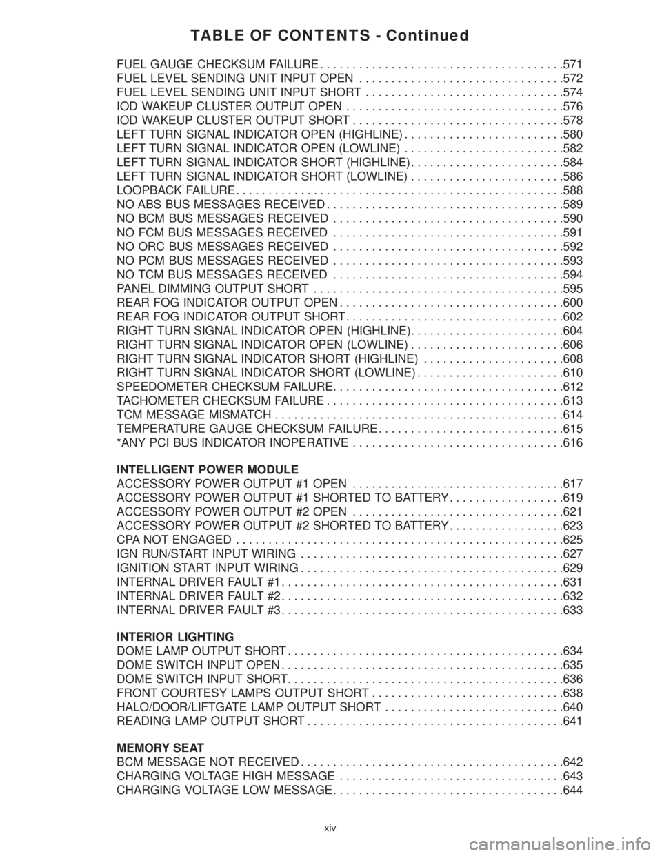
TABLE OF CONTENTS - Continued
FUEL GAUGE CHECKSUM FAILURE......................................571
FUEL LEVEL SENDING UNIT INPUT OPEN................................572
FUEL LEVEL SENDING UNIT INPUT SHORT...............................574
IOD WAKEUP CLUSTER OUTPUT OPEN..................................576
IOD WAKEUP CLUSTER OUTPUT SHORT.................................578
LEFT TURN SIGNAL INDICATOR OPEN (HIGHLINE).........................580
LEFT TURN SIGNAL INDICATOR OPEN (LOWLINE).........................582
LEFT TURN SIGNAL INDICATOR SHORT (HIGHLINE)........................584
LEFT TURN SIGNAL INDICATOR SHORT (LOWLINE)........................586
LOOPBACK FAILURE...................................................588
NO ABS BUS MESSAGES RECEIVED.....................................589
NO BCM BUS MESSAGES RECEIVED....................................590
NO FCM BUS MESSAGES RECEIVED....................................591
NO ORC BUS MESSAGES RECEIVED....................................592
NO PCM BUS MESSAGES RECEIVED....................................593
NO TCM BUS MESSAGES RECEIVED....................................594
PANEL DIMMING OUTPUT SHORT.......................................595
REAR FOG INDICATOR OUTPUT OPEN...................................600
REAR FOG INDICATOR OUTPUT SHORT..................................602
RIGHT TURN SIGNAL INDICATOR OPEN (HIGHLINE)........................604
RIGHT TURN SIGNAL INDICATOR OPEN (LOWLINE)........................606
RIGHT TURN SIGNAL INDICATOR SHORT (HIGHLINE)......................608
RIGHT TURN SIGNAL INDICATOR SHORT (LOWLINE).......................610
SPEEDOMETER CHECKSUM FAILURE....................................612
TACHOMETER CHECKSUM FAILURE.....................................613
TCM MESSAGE MISMATCH.............................................614
TEMPERATURE GAUGE CHECKSUM FAILURE.............................615
*ANY PCI BUS INDICATOR INOPERATIVE.................................616
INTELLIGENT POWER MODULE
ACCESSORY POWER OUTPUT #1 OPEN.................................617
ACCESSORY POWER OUTPUT #1 SHORTED TO BATTERY..................619
ACCESSORY POWER OUTPUT #2 OPEN.................................621
ACCESSORY POWER OUTPUT #2 SHORTED TO BATTERY..................623
CPA NOT ENGAGED...................................................625
IGN RUN/START INPUT WIRING.........................................627
IGNITION START INPUT WIRING.........................................629
INTERNAL DRIVER FAULT #1............................................631
INTERNAL DRIVER FAULT #2............................................632
INTERNAL DRIVER FAULT #3............................................633
INTERIOR LIGHTING
DOME LAMP OUTPUT SHORT...........................................634
DOME SWITCH INPUT OPEN............................................635
DOME SWITCH INPUT SHORT...........................................636
FRONT COURTESY LAMPS OUTPUT SHORT..............................638
HALO/DOOR/LIFTGATE LAMP OUTPUT SHORT............................640
READING LAMP OUTPUT SHORT........................................641
MEMORY SEAT
BCM MESSAGE NOT RECEIVED.........................................642
CHARGING VOLTAGE HIGH MESSAGE...................................643
CHARGING VOLTAGE LOW MESSAGE....................................644
xiv
Page 64 of 4284
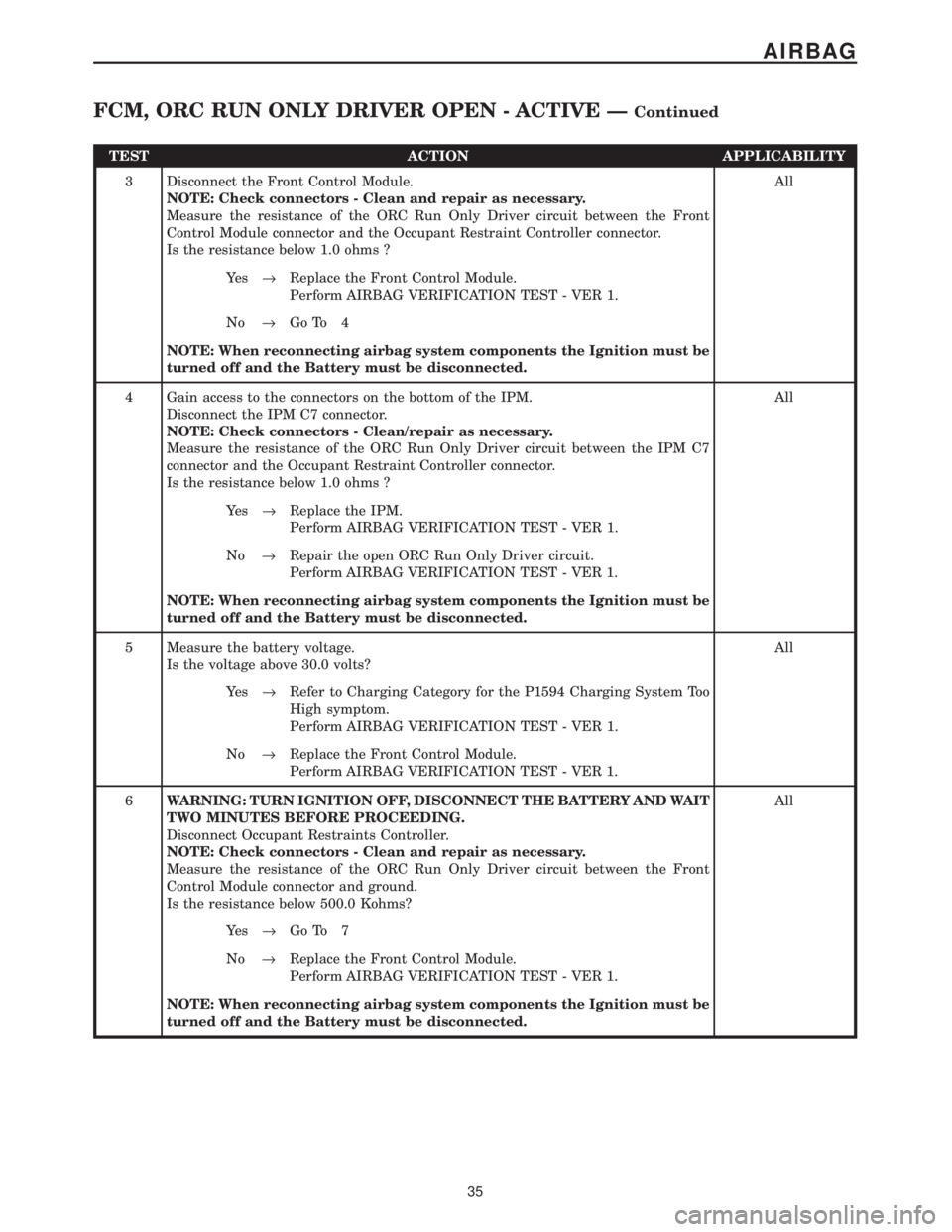
TEST ACTION APPLICABILITY
3 Disconnect the Front Control Module.
NOTE: Check connectors - Clean and repair as necessary.
Measure the resistance of the ORC Run Only Driver circuit between the Front
Control Module connector and the Occupant Restraint Controller connector.
Is the resistance below 1.0 ohms ?All
Ye s®Replace the Front Control Module.
Perform AIRBAG VERIFICATION TEST - VER 1.
No®Go To 4
NOTE: When reconnecting airbag system components the Ignition must be
turned off and the Battery must be disconnected.
4 Gain access to the connectors on the bottom of the IPM.
Disconnect the IPM C7 connector.
NOTE: Check connectors - Clean/repair as necessary.
Measure the resistance of the ORC Run Only Driver circuit between the IPM C7
connector and the Occupant Restraint Controller connector.
Is the resistance below 1.0 ohms ?All
Ye s®Replace the IPM.
Perform AIRBAG VERIFICATION TEST - VER 1.
No®Repair the open ORC Run Only Driver circuit.
Perform AIRBAG VERIFICATION TEST - VER 1.
NOTE: When reconnecting airbag system components the Ignition must be
turned off and the Battery must be disconnected.
5 Measure the battery voltage.
Is the voltage above 30.0 volts?All
Ye s®Refer to Charging Category for the P1594 Charging System Too
High symptom.
Perform AIRBAG VERIFICATION TEST - VER 1.
No®Replace the Front Control Module.
Perform AIRBAG VERIFICATION TEST - VER 1.
6WARNING: TURN IGNITION OFF, DISCONNECT THE BATTERY AND WAIT
TWO MINUTES BEFORE PROCEEDING.
Disconnect Occupant Restraints Controller.
NOTE: Check connectors - Clean and repair as necessary.
Measure the resistance of the ORC Run Only Driver circuit between the Front
Control Module connector and ground.
Is the resistance below 500.0 Kohms?All
Ye s®Go To 7
No®Replace the Front Control Module.
Perform AIRBAG VERIFICATION TEST - VER 1.
NOTE: When reconnecting airbag system components the Ignition must be
turned off and the Battery must be disconnected.
35
AIRBAG
FCM, ORC RUN ONLY DRIVER OPEN - ACTIVE ÐContinued
Page 73 of 4284
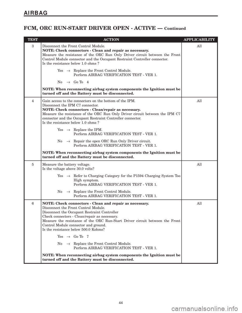
TEST ACTION APPLICABILITY
3 Disconnect the Front Control Module.
NOTE: Check connectors - Clean and repair as necessary.
Measure the resistance of the ORC Run Only Driver circuit between the Front
Control Module connector and the Occupant Restraint Controller connector.
Is the resistance below 1.0 ohms ?All
Ye s®Replace the Front Control Module.
Perform AIRBAG VERIFICATION TEST - VER 1.
No®Go To 4
NOTE: When reconnecting airbag system components the Ignition must be
turned off and the Battery must be disconnected.
4 Gain access to the connectors on the bottom of the IPM.
Disconnect the IPM C7 connector.
NOTE: Check connectors - Clean/repair as necessary.
Measure the resistance of the ORC Run Only Driver circuit between the IPM C7
connector and the Occupant Restraint Controller connector.
Is the resistance below 1.0 ohms ?All
Ye s®Replace the IPM.
Perform AIRBAG VERIFICATION TEST - VER 1.
No®Repair the open ORC Run Only Driver circuit.
Perform AIRBAG VERIFICATION TEST - VER 1.
NOTE: When reconnecting airbag system components the Ignition must be
turned off and the Battery must be disconnected.
5 Measure the battery voltage.
Is the voltage above 30.0 volts?All
Ye s®Refer to Charging Category for the P1594 Charging System Too
High symptom.
Perform AIRBAG VERIFICATION TEST - VER 1.
No®Replace the Front Control Module.
Perform AIRBAG VERIFICATION TEST - VER 1.
6NOTE: Check connectors - Clean and repair as necessary.
Disconnect the Front Control Module.
Disconnect the Occupant Restraint Controller
Check connectors - Clean/repair as necessary.
Measure the resistance of the ORC Run-Start Driver circuit between the Front
Control Module connector and ground.
Is the resistance below 500.0 Kohms?All
Ye s®Go To 7
No®Replace the Front Control Module.
Perform AIRBAG VERIFICATION TEST - VER 1.
NOTE: When reconnecting airbag system components the Ignition must be
turned off and the Battery must be disconnected.
44
AIRBAG
FCM, ORC RUN-START DRIVER OPEN - ACTIVE ÐContinued
Page 79 of 4284
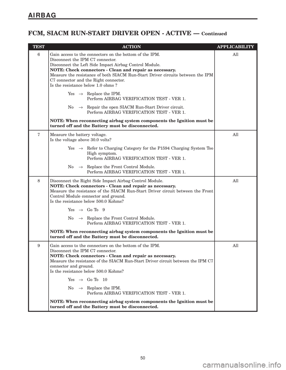
TEST ACTION APPLICABILITY
6 Gain access to the connectors on the bottom of the IPM.
Disconnect the IPM C7 connector.
Disconnect the Left Side Impact Airbag Control Module.
NOTE: Check connectors - Clean and repair as necessary.
Measure the resistance of both SIACM Run-Start Driver circuits between the IPM
C7 connector and the Right connector.
Is the resistance below 1.0 ohms ?All
Ye s®Replace the IPM.
Perform AIRBAG VERIFICATION TEST - VER 1.
No®Repair the open SIACM Run-Start Driver circuit.
Perform AIRBAG VERIFICATION TEST - VER 1.
NOTE: When reconnecting airbag system components the Ignition must be
turned off and the Battery must be disconnected.
7 Measure the battery voltage.
Is the voltage above 30.0 volts?All
Ye s®Refer to Charging Category for the P1594 Charging System Too
High symptom.
Perform AIRBAG VERIFICATION TEST - VER 1.
No®Replace the Front Control Module.
Perform AIRBAG VERIFICATION TEST - VER 1.
8 Disconnect the Right Side Impact Airbag Control Module.
NOTE: Check connectors - Clean and repair as necessary.
Measure the resistance of the SIACM Run-Start Driver circuit between the Front
Control Module connector and ground.
Is the resistance below 500.0 Kohms?All
Ye s®Go To 9
No®Replace the Front Control Module.
Perform AIRBAG VERIFICATION TEST - VER 1.
NOTE: When reconnecting airbag system components the Ignition must be
turned off and the Battery must be disconnected.
9 Gain access to the connectors on the bottom of the IPM.
Disconnect the IPM C7 connector.
NOTE: Check connectors - Clean and repair as necessary.
Measure the resistance of the SIACM Run-Start Driver circuit between the IPM C7
connector and ground.
Is the resistance below 500.0 Kohms?All
Ye s®Go To 10
No®Replace the IPM.
Perform AIRBAG VERIFICATION TEST - VER 1.
NOTE: When reconnecting airbag system components the Ignition must be
turned off and the Battery must be disconnected.
50
AIRBAG
FCM, SIACM RUN-START DRIVER OPEN - ACTIVE ÐContinued
Page 226 of 4284
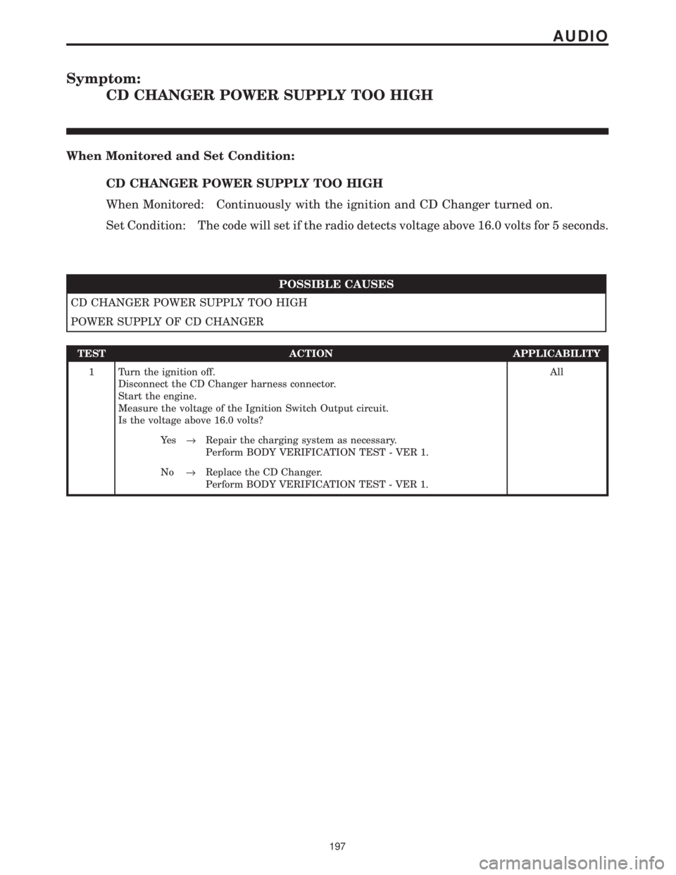
Symptom:
CD CHANGER POWER SUPPLY TOO HIGH
When Monitored and Set Condition:
CD CHANGER POWER SUPPLY TOO HIGH
When Monitored: Continuously with the ignition and CD Changer turned on.
Set Condition: The code will set if the radio detects voltage above 16.0 volts for 5 seconds.
POSSIBLE CAUSES
CD CHANGER POWER SUPPLY TOO HIGH
POWER SUPPLY OF CD CHANGER
TEST ACTION APPLICABILITY
1 Turn the ignition off.
Disconnect the CD Changer harness connector.
Start the engine.
Measure the voltage of the Ignition Switch Output circuit.
Is the voltage above 16.0 volts?All
Ye s®Repair the charging system as necessary.
Perform BODY VERIFICATION TEST - VER 1.
No®Replace the CD Changer.
Perform BODY VERIFICATION TEST - VER 1.
197
AUDIO
Page 242 of 4284
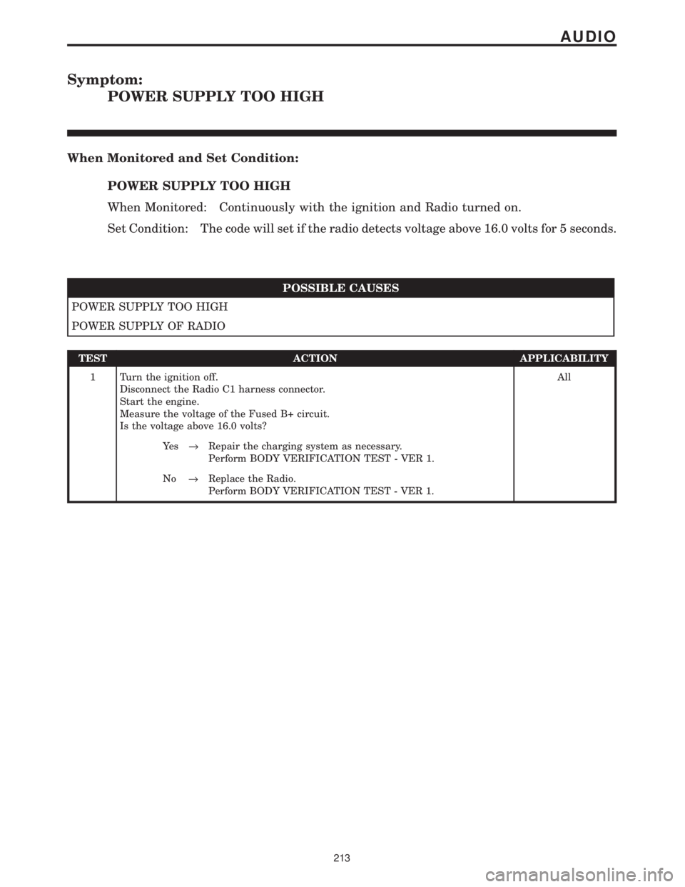
Symptom:
POWER SUPPLY TOO HIGH
When Monitored and Set Condition:
POWER SUPPLY TOO HIGH
When Monitored: Continuously with the ignition and Radio turned on.
Set Condition: The code will set if the radio detects voltage above 16.0 volts for 5 seconds.
POSSIBLE CAUSES
POWER SUPPLY TOO HIGH
POWER SUPPLY OF RADIO
TEST ACTION APPLICABILITY
1 Turn the ignition off.
Disconnect the Radio C1 harness connector.
Start the engine.
Measure the voltage of the Fused B+ circuit.
Is the voltage above 16.0 volts?All
Ye s®Repair the charging system as necessary.
Perform BODY VERIFICATION TEST - VER 1.
No®Replace the Radio.
Perform BODY VERIFICATION TEST - VER 1.
213
AUDIO
Page 333 of 4284

Symptom:
B1802 POWER SUPPLY OUT OF RANGE: LOW VOLTAGE THRESH-
OLD
When Monitored and Set Condition:
B1802 POWER SUPPLY OUT OF RANGE: LOW VOLTAGE THRESHOLD
When Monitored: With the engine running.
Set Condition: This DTC will set if the DCHA's power supply voltage drops below 10.0
volts for longer than 20 seconds.
POSSIBLE CAUSES
FIELD MODE TEST RUN WITH THE ENGINE OFF
VEHICLE'S BATTERY SYSTEM
VEHICLE'S CHARGING SYSTEM NOT OPERATING PROPERLY
DCHA CONTROL UNIT FAULT
FUSED B+ CIRCUIT HIGH RESISTANCE
DCHA CONTROL UNIT FAULT
TEST ACTION APPLICABILITY
1WARNING: DO NOT OPERATE THE DCHA IN AN ENCLOSED AREA SUCH
AS A GARAGE THAT DOES NOT HAVE EXHAUST VENTILATION FACILI-
TIES. ALWAYS VENT THE DCHA's EXHAUST WHEN OPERATING THE
DCHA. FAILURE TO FOLLOW THESE INSTRUCTIONS MAY RESULT IN
PERSONAL INJURY OR DEATH.
CAUTION: DO NOT PERFORM THIS TEST UNLESS DIRECTED HERE BY
THE CABIN HEATER PRE-TEST. ALWAYS PERFORM THE CABIN HEATER
PRE-TEST PRIOR TO PERFORMING ANY OTHER CABIN HEATER TEST
FOR THE RESULT TO BE VALID.
Was the Field Mode Test run with the engine off?All
Ye s®Rerun the Field Mode Test exactly as it is described in Test 4 of
the Cabin Heater Pre-Test. If DTC B1802 resets, Go To Test #2 of
this symptom. Otherwise, perform other diagnosis and testing as
necessary.
Perform CABIN HEATER VERIFICATION TEST - VER 1.
No®Go To 2
304
CABIN HEATER
Page 334 of 4284
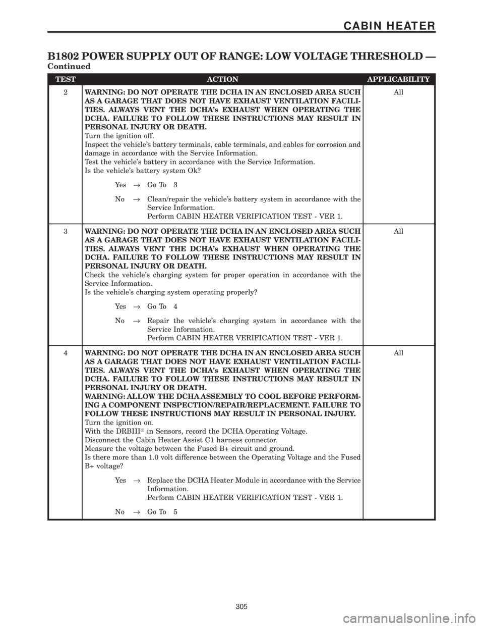
TEST ACTION APPLICABILITY
2WARNING: DO NOT OPERATE THE DCHA IN AN ENCLOSED AREA SUCH
AS A GARAGE THAT DOES NOT HAVE EXHAUST VENTILATION FACILI-
TIES. ALWAYS VENT THE DCHA's EXHAUST WHEN OPERATING THE
DCHA. FAILURE TO FOLLOW THESE INSTRUCTIONS MAY RESULT IN
PERSONAL INJURY OR DEATH.
Turn the ignition off.
Inspect the vehicle's battery terminals, cable terminals, and cables for corrosion and
damage in accordance with the Service Information.
Test the vehicle's battery in accordance with the Service Information.
Is the vehicle's battery system Ok?All
Ye s®Go To 3
No®Clean/repair the vehicle's battery system in accordance with the
Service Information.
Perform CABIN HEATER VERIFICATION TEST - VER 1.
3WARNING: DO NOT OPERATE THE DCHA IN AN ENCLOSED AREA SUCH
AS A GARAGE THAT DOES NOT HAVE EXHAUST VENTILATION FACILI-
TIES. ALWAYS VENT THE DCHA's EXHAUST WHEN OPERATING THE
DCHA. FAILURE TO FOLLOW THESE INSTRUCTIONS MAY RESULT IN
PERSONAL INJURY OR DEATH.
Check the vehicle's charging system for proper operation in accordance with the
Service Information.
Is the vehicle's charging system operating properly?All
Ye s®Go To 4
No®Repair the vehicle's charging system in accordance with the
Service Information.
Perform CABIN HEATER VERIFICATION TEST - VER 1.
4WARNING: DO NOT OPERATE THE DCHA IN AN ENCLOSED AREA SUCH
AS A GARAGE THAT DOES NOT HAVE EXHAUST VENTILATION FACILI-
TIES. ALWAYS VENT THE DCHA's EXHAUST WHEN OPERATING THE
DCHA. FAILURE TO FOLLOW THESE INSTRUCTIONS MAY RESULT IN
PERSONAL INJURY OR DEATH.
WARNING: ALLOW THE DCHA ASSEMBLY TO COOL BEFORE PERFORM-
ING A COMPONENT INSPECTION/REPAIR/REPLACEMENT. FAILURE TO
FOLLOW THESE INSTRUCTIONS MAY RESULT IN PERSONAL INJURY.
Turn the ignition on.
With the DRBIIItin Sensors, record the DCHA Operating Voltage.
Disconnect the Cabin Heater Assist C1 harness connector.
Measure the voltage between the Fused B+ circuit and ground.
Is there more than 1.0 volt difference between the Operating Voltage and the Fused
B+ voltage?All
Ye s®Replace the DCHA Heater Module in accordance with the Service
Information.
Perform CABIN HEATER VERIFICATION TEST - VER 1.
No®Go To 5
305
CABIN HEATER
B1802 POWER SUPPLY OUT OF RANGE: LOW VOLTAGE THRESHOLD Ð
Continued