2001 CHRYSLER VOYAGER refrigerant type
[x] Cancel search: refrigerant typePage 3640 of 4284
A/C PRESSURE TRANSDUCER
DESCRIPTION
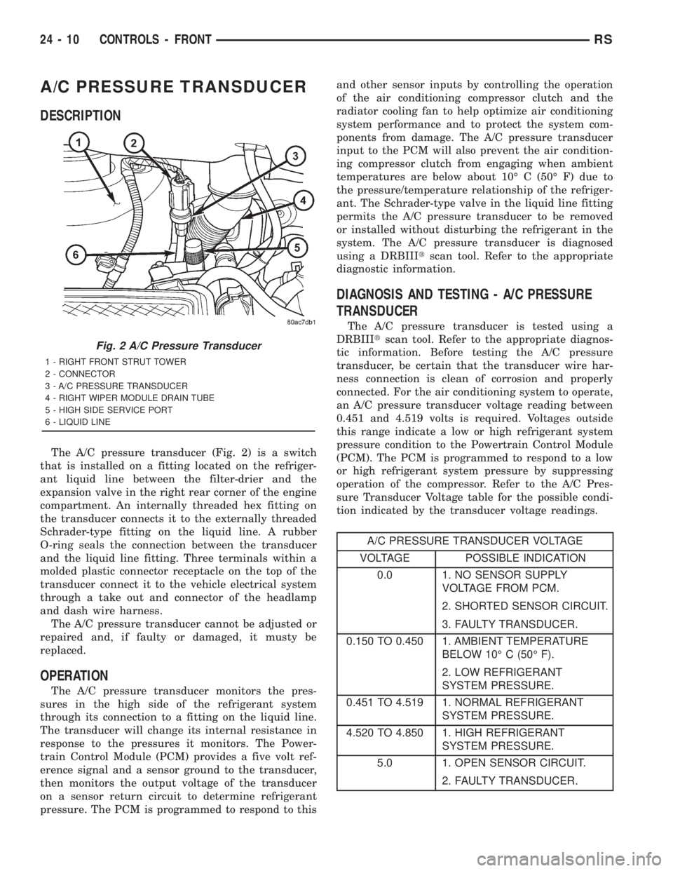
The A/C pressure transducer (Fig. 2) is a switch
that is installed on a fitting located on the refriger-
ant liquid line between the filter-drier and the
expansion valve in the right rear corner of the engine
compartment. An internally threaded hex fitting on
the transducer connects it to the externally threaded
Schrader-type fitting on the liquid line. A rubber
O-ring seals the connection between the transducer
and the liquid line fitting. Three terminals within a
molded plastic connector receptacle on the top of the
transducer connect it to the vehicle electrical system
through a take out and connector of the headlamp
and dash wire harness.
The A/C pressure transducer cannot be adjusted or
repaired and, if faulty or damaged, it musty be
replaced.
OPERATION
The A/C pressure transducer monitors the pres-
sures in the high side of the refrigerant system
through its connection to a fitting on the liquid line.
The transducer will change its internal resistance in
response to the pressures it monitors. The Power-
train Control Module (PCM) provides a five volt ref-
erence signal and a sensor ground to the transducer,
then monitors the output voltage of the transducer
on a sensor return circuit to determine refrigerant
pressure. The PCM is programmed to respond to thisand other sensor inputs by controlling the operation
of the air conditioning compressor clutch and the
radiator cooling fan to help optimize air conditioning
system performance and to protect the system com-
ponents from damage. The A/C pressure transducer
input to the PCM will also prevent the air condition-
ing compressor clutch from engaging when ambient
temperatures are below about 10É C (50É F) due to
the pressure/temperature relationship of the refriger-
ant. The Schrader-type valve in the liquid line fitting
permits the A/C pressure transducer to be removed
or installed without disturbing the refrigerant in the
system. The A/C pressure transducer is diagnosed
using a DRBIIItscan tool. Refer to the appropriate
diagnostic information.
DIAGNOSIS AND TESTING - A/C PRESSURE
TRANSDUCER
The A/C pressure transducer is tested using a
DRBIIItscan tool. Refer to the appropriate diagnos-
tic information. Before testing the A/C pressure
transducer, be certain that the transducer wire har-
ness connection is clean of corrosion and properly
connected. For the air conditioning system to operate,
an A/C pressure transducer voltage reading between
0.451 and 4.519 volts is required. Voltages outside
this range indicate a low or high refrigerant system
pressure condition to the Powertrain Control Module
(PCM). The PCM is programmed to respond to a low
or high refrigerant system pressure by suppressing
operation of the compressor. Refer to the A/C Pres-
sure Transducer Voltage table for the possible condi-
tion indicated by the transducer voltage readings.
A/C PRESSURE TRANSDUCER VOLTAGE
VOLTAGE POSSIBLE INDICATION
0.0 1. NO SENSOR SUPPLY
VOLTAGE FROM PCM.
2. SHORTED SENSOR CIRCUIT.
3. FAULTY TRANSDUCER.
0.150 TO 0.450 1. AMBIENT TEMPERATURE
BELOW 10É C (50É F).
2. LOW REFRIGERANT
SYSTEM PRESSURE.
0.451 TO 4.519 1. NORMAL REFRIGERANT
SYSTEM PRESSURE.
4.520 TO 4.850 1. HIGH REFRIGERANT
SYSTEM PRESSURE.
5.0 1. OPEN SENSOR CIRCUIT.
2. FAULTY TRANSDUCER.
Fig. 2 A/C Pressure Transducer
1 - RIGHT FRONT STRUT TOWER
2 - CONNECTOR
3 - A/C PRESSURE TRANSDUCER
4 - RIGHT WIPER MODULE DRAIN TUBE
5 - HIGH SIDE SERVICE PORT
6 - LIQUID LINE
24 - 10 CONTROLS - FRONTRS
Page 3648 of 4284
ELECTRICAL/ELECTRONIC CONTROL MOD-
ULES/POWERTRAIN CONTROL MODULE -
DESCRIPTION - PCM OPERATION).
STANDARD PROCEDURE - COMPRESSOR
CLUTCH AIR GAP
If a new clutch plate and/or clutch pulley are being
used, the air gap between the clutch plate and clutch
pulley must be checked using the following proce-
dure:
(1) Using feeler gauges, measure the air gap
between the clutch plate and the clutch pulley fric-
tion surfaces.
(2) If the air gap is not between 0.5 and 0.9 mm
(0.020 and 0.035 in.), add or subtract shims until the
desired air gap is obtained.
NOTE: The shims may compress after tightening
the compressor shaft bolt. Check the air gap in four
or more places on the clutch plate to verify that the
air gap is still correct. Spin the clutch pulley before
making the final air gap check.
STANDARD PROCEDURE - COMPRESSOR
CLUTCH BREAK-IN
After a new compressor clutch has been installed,
check that the compressor clutch coil is performing to
specifications. (Refer to 24 - HEATING & AIR CON-
DITIONING/CONTROLS - FRONT/COMPRESSOR
CLUTCH COIL - DIAGNOSIS AND TESTING). If
the clutch coil is performing to specifications, per-
form the compressor clutch break-in procedure. This
procedure (burnishing) will seat the opposing friction
surfaces and provide a higher compressor clutch
torque capability.
(1) Set the heater-A/C controls to the A/C mode,
with the blower switch in the highest speed position.
(2) Start the engine and hold the engine speed at
1500 to 2000 rpm.
(3) Cycle the compressor clutch On and Off about
twenty times (five seconds On, then five seconds Off).
REMOVAL
The refrigerant system can remain fully charged
during compressor clutch, pulley, or coil replacement.
Although the compressor assembly must be removed
from its mounting, the compressor clutch can be ser-
vice with the compressor in the vehicle.
(1) Disconnect and isolate the battery negative
cable.
(2) Raise and support the vehicle.
(3) Remove the serpentine drive belt. (Refer to 7 -
COOLING/ACCESSORY DRIVE/DRIVE BELTS -
2.4L - REMOVAL) or (Refer to 7 - COOLING/ACCES-SORY DRIVE/DRIVE BELTS - 3.3/3.8L - REMOV-
AL).
(4) Disconnect the engine wire harness connector
for the compressor clutch coil from the clutch coil pig-
tail wire connector on the top of the compressor.
(5) On models with the 3.3L and 3.8L engines, dis-
engage the retainer on the engine wire harness com-
pressor clutch coil take out from the bracket on the
top of the compressor.
(6) On models with the 2.4L engine, remove all of
the compressor mounting screws except the upper
left (rear of the compressor) screw, which should only
be loosened. Allow the front (pulley end) of the com-
pressor to tilt downward far enough to access the
clutch for removal, then tighten the loosened upper
left compressor mounting screw.
(7) On models with the 3.3L and 3.8L engines,
remove the three screws and one nut that secure the
compressor to the engine. Disengage the mounting
ear at the front of the compressor from the stud on
the engine, allow the front (pulley end) of the com-
pressor to tilt downward far enough to access the
clutch for removal, then reinstall and tighten the
upper left compressor mounting screw.
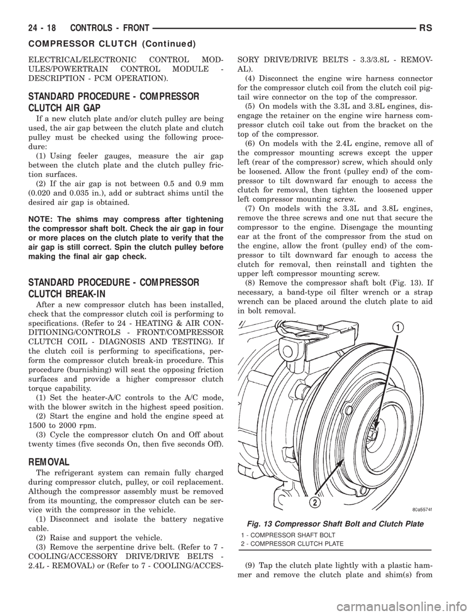
(8) Remove the compressor shaft bolt (Fig. 13). If
necessary, a band-type oil filter wrench or a strap
wrench can be placed around the clutch plate to aid
in bolt removal.
(9) Tap the clutch plate lightly with a plastic ham-
mer and remove the clutch plate and shim(s) from
Fig. 13 Compressor Shaft Bolt and Clutch Plate
1 - COMPRESSOR SHAFT BOLT
2 - COMPRESSOR CLUTCH PLATE
24 - 18 CONTROLS - FRONTRS
COMPRESSOR CLUTCH (Continued)
Page 3650 of 4284
packing from around the compressor shaft in the
compressor front cover. If the felt is saturated with
oil, the compressor front shaft seal is leaking and the
compressor will also have to be replaced.
(3) Check the clutch pulley bearing for roughness
or excessive leakage of grease. Replace the clutch
pulley and clutch plate if the bearing is faulty.
INSTALLATION
The refrigerant system can remain fully charged
during compressor clutch, pulley, or coil replacement.
Although the compressor assembly must be removed
from its mounting, the compressor clutch can be ser-
vice with the compressor in the vehicle.
(1) Align the dowel pin on the back of the clutch
coil with the hole in the compressor front cover, and
position the clutch coil onto the compressor. Be cer-
tain that the clutch coil pigtail wires are properly ori-
ented and routed so that they are not pinched
between the compressor front cover and the clutch
coil.
NOTE: A new snap ring must be used to secure the
clutch coil to the compressor. The bevel side of the
snap ring must face outward.
(2) Using snap ring pliers (Special Tool C-4574 or
equivalent), install the external snap ring that
secures the clutch coil to the front cover of the com-
pressor (Fig. 16). The bevel side of the snap ring
must face outward and both snap ring eyelets must
be oriented to the right or the left of the clutch coil
dowel pin location on the compressor. Be certain that
the snap ring is fully and properly seated in the
groove.
CAUTION: If the snap ring is not fully seated in the
groove it will vibrate out, resulting in a clutch fail-
ure and severe damage to the compressor front
cover.
(3) Install and tighten the screw that secures the
clutch coil pigtail wire connector bracket and ground
clip to the top of the compressor housing.
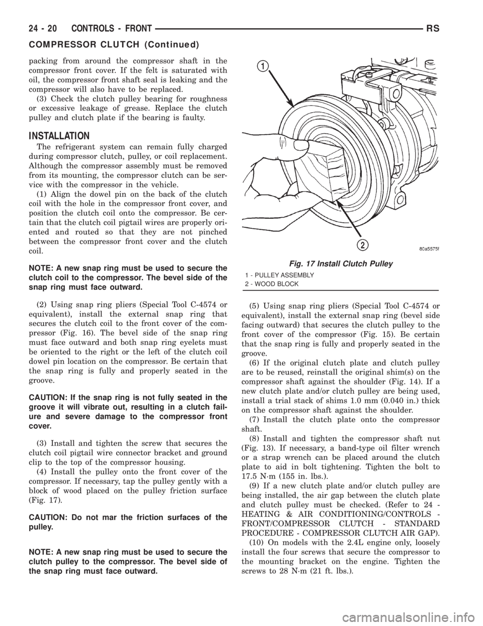
(4) Install the pulley onto the front cover of the
compressor. If necessary, tap the pulley gently with a
block of wood placed on the pulley friction surface
(Fig. 17).
CAUTION: Do not mar the friction surfaces of the
pulley.
NOTE: A new snap ring must be used to secure the
clutch pulley to the compressor. The bevel side of
the snap ring must face outward.(5) Using snap ring pliers (Special Tool C-4574 or
equivalent), install the external snap ring (bevel side
facing outward) that secures the clutch pulley to the
front cover of the compressor (Fig. 15). Be certain
that the snap ring is fully and properly seated in the
groove.
(6) If the original clutch plate and clutch pulley
are to be reused, reinstall the original shim(s) on the
compressor shaft against the shoulder (Fig. 14). If a
new clutch plate and/or clutch pulley are being used,
install a trial stack of shims 1.0 mm (0.040 in.) thick
on the compressor shaft against the shoulder.
(7) Install the clutch plate onto the compressor
shaft.
(8) Install and tighten the compressor shaft nut
(Fig. 13). If necessary, a band-type oil filter wrench
or a strap wrench can be placed around the clutch
plate to aid in bolt tightening. Tighten the bolt to
17.5 N´m (155 in. lbs.).
(9) If a new clutch plate and/or clutch pulley are
being installed, the air gap between the clutch plate
and clutch pulley must be checked. (Refer to 24 -
HEATING & AIR CONDITIONING/CONTROLS -
FRONT/COMPRESSOR CLUTCH - STANDARD
PROCEDURE - COMPRESSOR CLUTCH AIR GAP).
(10) On models with the 2.4L engine only, loosely
install the four screws that secure the compressor to
the mounting bracket on the engine. Tighten the
screws to 28 N´m (21 ft. lbs.).
Fig. 17 Install Clutch Pulley
1 - PULLEY ASSEMBLY
2 - WOOD BLOCK
24 - 20 CONTROLS - FRONTRS
COMPRESSOR CLUTCH (Continued)
Page 3696 of 4284
(9) Remove the seal from the discharge line fitting
and discard.
(10) Install plugs in, or tape over the opened dis-
charge line fitting and the compressor discharge port.
(11) Raise and support the vehicle.
(12) Remove the serpentine accessory drive belt
from the front of the engine. (Refer to 7 - COOLING/
ACCESSORY DRIVE/DRIVE BELTS - 2.4L -
REMOVAL) or (Refer to 7 - COOLING/ACCESSORY
DRIVE/DRIVE BELTS - 3.3L/3.8L - REMOVAL).
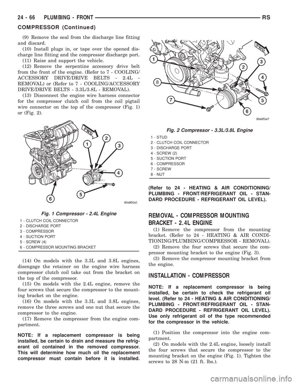
(13) Disconnect the engine wire harness connector
for the compressor clutch coil from the coil pigtail
wire connector on the top of the compressor (Fig. 1)
or (Fig. 2).
(14) On models with the 3.3L and 3.8L engines,
disengage the retainer on the engine wire harness
compressor clutch coil take out from the bracket on
the top of the compressor.
(15) On models with the 2.4L engine, remove the
four screws that secure the compressor to the mount-
ing bracket on the engine.
(16) On models with the 3.3L and 3.8L engines,
remove the three screws and one nut that secure the
compressor to the engine.
(17) Remove the compressor from the engine com-
partment.
NOTE: If a replacement compressor is being
installed, be certain to drain and measure the refrig-
erant oil contained in the removed compressor.
This will determine how much oil the replacement
compressor must contain before it is installed.(Refer to 24 - HEATING & AIR CONDITIONING/
PLUMBING - FRONT/REFRIGERANT OIL - STAN-
DARD PROCEDURE - REFRIGERANT OIL LEVEL).
REMOVAL - COMPRESSOR MOUNTING
BRACKET - 2.4L ENGINE
(1) Remove the compressor from the mounting
bracket. (Refer to 24 - HEATING & AIR CONDI-
TIONING/PLUMBING/COMPRESSOR - REMOVAL).
(2) Remove the four screws that secure the com-
pressor mounting bracket to the engine (Fig. 3).
(3) Remove the compressor mounting bracket from
the engine.
INSTALLATION - COMPRESSOR
NOTE: If a replacement compressor is being
installed, be certain to check the refrigerant oil
level. (Refer to 24 - HEATING & AIR CONDITIONING/
PLUMBING - FRONT/REFRIGERANT OIL - STAN-
DARD PROCEDURE - REFRIGERANT OIL LEVEL).
Use only refrigerant oil of the type recommended
for the compressor in the vehicle.
(1) Position the compressor into the engine com-
partment.
(2) On models with the 2.4L engine, loosely install
the four screws that secure the compressor to the
mounting bracket on the engine (Fig. 1). Tighten the
screws to 28 N´m (21 ft. lbs.).
Fig. 1 Compressor - 2.4L Engine
1 - CLUTCH COIL CONNECTOR
2 - DISCHARGE PORT
3 - COMPRESSOR
4 - SUCTION PORT
5 - SCREW (4)
6 - COMPRESSOR MOUNTING BRACKET
Fig. 2 Compressor - 3.3L/3.8L Engine
1 - STUD
2 - CLUTCH COIL CONNECTOR
3 - DISCHARGE PORT
4 - SCREW (2)
5 - SUCTION PORT
6 - COMPRESSOR
7 - SCREW
8 - NUT
24 - 66 PLUMBING - FRONTRS
COMPRESSOR (Continued)
Page 3699 of 4284
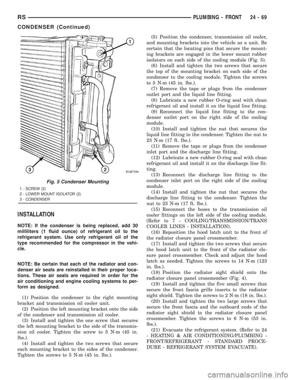
INSTALLATION
NOTE: If the condenser is being replaced, add 30
milliliters (1 fluid ounce) of refrigerant oil to the
refrigerant system. Use only refrigerant oil of the
type recommended for the compressor in the vehi-
cle.
NOTE: Be certain that each of the radiator and con-
denser air seals are reinstalled in their proper loca-
tions. These air seals are required in order for the
air conditioning and engine cooling systems to per-
form as designed.
(1) Position the condenser to the right mounting
bracket and transmission oil cooler unit.
(2) Position the left mounting bracket onto the side
of the condenser and transmission oil cooler.
(3) Install and tighten the one screw that secures
the left mounting bracket to the side of the transmis-
sion oil cooler. Tighten the screw to 5 N´m (45 in.
lbs.).
(4) Install and tighten the two screws that secure
each mounting bracket to the sides of the condenser.
Tighten the screws to 5 N´m (45 in. lbs.).(5) Position the condenser, transmission oil cooler,
and mounting brackets into the vehicle as a unit. Be
certain that the locating pins that secure the mount-
ing brackets are engaged in the lower mount rubber
isolators on each side of the cooling module (Fig. 5).
(6) Install and tighten the two screws that secure
the top of the mounting bracket on each side of the
condenser to the cooling module. Tighten the screws
to 5 N´m (45 in. lbs.).
(7) Remove the tape or plugs from the condenser
outlet port and the liquid line fitting.
(8) Lubricate a new rubber O-ring seal with clean
refrigerant oil and install it on the liquid line fitting.
(9) Reconnect the liquid line fitting to the con-
denser outlet port on the right side of the cooling
module.
(10) Install and tighten the nut that secures the
liquid line fitting to the condenser. Tighten the nut to
23 N´m (17 ft. lbs.).
(11) Remove the tape or plugs from the condenser
inlet port and the discharge line fitting.
(12) Lubricate a new rubber O-ring seal with clean
refrigerant oil and install it on the discharge line fit-
ting.
(13) Reconnect the discharge line fitting to the
condenser inlet port on the right side of the cooling
module.
(14) Install and tighten the nut that secures the
discharge line fitting to the condenser. Tighten the
nut to 23 N´m (17 ft. lbs.).
(15) Reconnect the hoses to the transmission oil
cooler fittings on the left side of the cooling module.
(Refer to 7 - COOLING/TRANSMISSION/TRANS
COOLER LINES - INSTALLATION).
(16) Reposition the hood latch unit to the front of
the radiator closure panel crossmember.
(17) Install and tighten the two screws that secure
the hood latch unit to the front of the radiator clo-
sure panel crossmember. Check and adjust the hood
latch as needed. Tighten the screws to 14 N´m (123
in. lbs.).
(18) Position the radiator sight shield onto the
radiator closure panel crossmember (Fig. 4).
(19) Install and tighten the five small screws that
secure the front fascia grille inserts to the radiator
sight shield. Tighten the screws to 2 N´m (18 in. lbs.).
(20) Install and tighten the two large screws that
secure the front fascia and the outboard ends of the
radiator sight shield to the radiator closure panel
crossmember. Tighten the screws to 6 N´m (53 in.
lbs.).
(21) Evacuate the refrigerant system. (Refer to 24
- HEATING & AIR CONDITIONING/PLUMBING -
FRONT/REFRIGERANT - STANDARD PROCE-
DURE - REFRIGERANT SYSTEM EVACUATE).
Fig. 5 Condenser Mounting
1 - SCREW (2)
2 - LOWER MOUNT ISOLATOR (2)
3 - CONDENSER
RSPLUMBING - FRONT24-69
CONDENSER (Continued)
Page 3703 of 4284
as a unit. Be certain not to lose the clam shell type
rubber seal that is fitted to the evaporator inlet and
outlet tubes where they exit the evaporator housing.
INSTALLATION
NOTE: If the evaporator is being replaced, add 60
milliliters (2 fluid ounces) of refrigerant oil to the
refrigerant system. Use only refrigerant oil of thetype recommended for the compressor in the vehi-
cle.
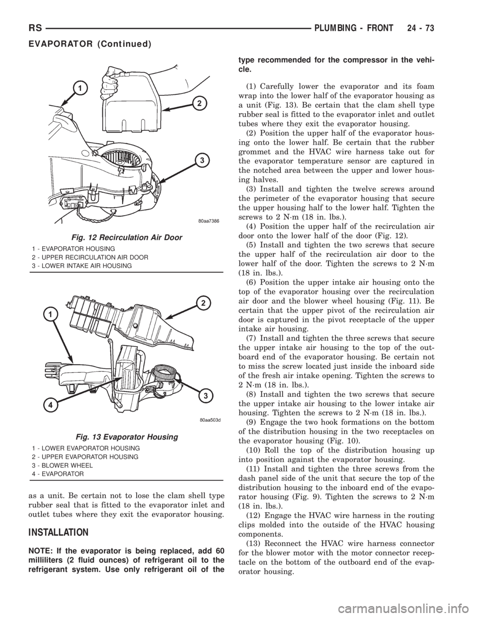
(1) Carefully lower the evaporator and its foam
wrap into the lower half of the evaporator housing as
a unit (Fig. 13). Be certain that the clam shell type
rubber seal is fitted to the evaporator inlet and outlet
tubes where they exit the evaporator housing.
(2) Position the upper half of the evaporator hous-
ing onto the lower half. Be certain that the rubber
grommet and the HVAC wire harness take out for
the evaporator temperature sensor are captured in
the notched area between the upper and lower hous-
ing halves.
(3) Install and tighten the twelve screws around
the perimeter of the evaporator housing that secure
the upper housing half to the lower half. Tighten the
screws to 2 N´m (18 in. lbs.).
(4) Position the upper half of the recirculation air
door onto the lower half of the door (Fig. 12).
(5) Install and tighten the two screws that secure
the upper half of the recirculation air door to the
lower half of the door. Tighten the screws to 2 N´m
(18 in. lbs.).
(6) Position the upper intake air housing onto the
top of the evaporator housing over the recirculation
air door and the blower wheel housing (Fig. 11). Be
certain that the upper pivot of the recirculation air
door is captured in the pivot receptacle of the upper
intake air housing.
(7) Install and tighten the three screws that secure
the upper intake air housing to the top of the out-
board end of the evaporator housing. Be certain not
to miss the screw located just inside the inboard side
of the fresh air intake opening. Tighten the screws to
2 N´m (18 in. lbs.).
(8) Install and tighten the two screws that secure
the upper intake air housing to the lower intake air
housing. Tighten the screws to 2 N´m (18 in. lbs.).
(9) Engage the two hook formations on the bottom
of the distribution housing in the two receptacles on
the evaporator housing (Fig. 10).
(10) Roll the top of the distribution housing up
into position against the evaporator housing.
(11) Install and tighten the three screws from the
dash panel side of the unit that secure the top of the
distribution housing to the inboard end of the evapo-
rator housing (Fig. 9). Tighten the screws to 2 N´m
(18 in. lbs.).
(12) Engage the HVAC wire harness in the routing
clips molded into the outside of the HVAC housing
components.
(13) Reconnect the HVAC wire harness connector
for the blower motor with the motor connector recep-
tacle on the bottom of the outboard end of the evap-
orator housing.
Fig. 12 Recirculation Air Door
1 - EVAPORATOR HOUSING
2 - UPPER RECIRCULATION AIR DOOR
3 - LOWER INTAKE AIR HOUSING
Fig. 13 Evaporator Housing
1 - LOWER EVAPORATOR HOUSING
2 - UPPER EVAPORATOR HOUSING
3 - BLOWER WHEEL
4 - EVAPORATOR
RSPLUMBING - FRONT24-73
EVAPORATOR (Continued)
Page 3704 of 4284
(14) Reinstall the expansion valve onto the evapo-
rator inlet and outlet tube fittings. (Refer to 24 -
HEATING & AIR CONDITIONING/PLUMBING -
FRONT/EXPANSION VALVE - INSTALLATION).
(15) Install a new foam seal onto the HVAC hous-
ing seal flange around the fresh air inlet opening and
the expansion valve/evaporator tube opening on the
dash panel side of the unit.
(16) Reinstall the heater core tubes into the heater
core. (Refer to 24 - HEATING & AIR CONDITION-
ING/PLUMBING - FRONT/HEATER CORE -
INSTALLATION - HEATER CORE TUBES).
(17) Reinstall the HVAC unit housing into the
vehicle. (Refer to 24 - HEATING & AIR CONDI-
TIONING/DISTRIBUTION - FRONT/HVAC HOUS-
ING - INSTALLATION).
EXPANSION VALVE
DESCRIPTION
The front ªHº valve-type thermal expansion valve
(TXV) is located at the dash panel between the liquid
and suction lines, and the evaporator coil. The
assembly consists of an H-valve body and a thermal
sensor. High-pressure, low temperature liquid refrig-
erant from the liquid line passes through the expan-
sion valve orifice, converting it into a low-pressure,
low-temperature mixture of liquid and gas before it
enters the evaporator coil. The expansion valve is a
factory calibrated unit and cannot be adjusted or
repaired. If faulty or damaged, the expansion valve
must be replaced.
OPERATION
A mechanical sensor in the expansion valve control
head monitors the temperature and pressure of the
refrigerant leaving the evaporator coil through the
suction line, and adjusts the orifice size at the liquid
line to let the proper amount of refrigerant into the
evaporator coil to meet the vehicle cooling require-
ments. Controlling the refrigerant flow through the
evaporator ensures that none of the refrigerant leav-
ing the evaporator is still in a liquid state, which
could damage the compressor. The thermo sensor
measures refrigerant liquid temperature which is
monitored by the a/c control assembly.
DIAGNOSIS AND TESTING - EXPANSION VALVE
WARNING: REFER TO THE APPLICABLE WARN-
INGS AND CAUTIONS FOR THIS SYSTEM BEFORE
PERFORMING THE FOLLOWING OPERATION.
(Refer to 24 - HEATING & AIR CONDITIONING/
PLUMBING - FRONT - WARNING - A/C PLUMBING)and (Refer to 24 - HEATING & AIR CONDITIONING/
PLUMBING - FRONT - CAUTION - A/C PLUMBING).
NOTE: The expansion valve should only be tested
following testing of the compressor.
NOTE: Liquid CO
2is required to test the expansion
valve. This material is available from most welding
supply facilities. Liquid CO
2is also available from
companies which service and sell fire extinguish-
ers.
When testing the expansion valve, the work area
and the vehicle temperature must be 21É to 27É C
(70É to 85É F). To test the expansion valve:
(1) Connect a charging station or manifold gauge
set to the refrigerant system service ports. Verify the
refrigerant charge level.
(2) Close all doors, windows and vents to the pas-
senger compartment.
(3) Set the heater-air conditioner controls so that
the compressor is operating, the temperature control
is in the highest temperature position, the mode door
is directing the output to the floor outlets, and the
blower is operating at the highest speed setting.
(4) Start the engine and allow it to idle at 1000
rpm. After the engine has reached normal operating
temperature, allow the passenger compartment to
heat up. This will create the need for maximum
refrigerant flow into the evaporator.
(5) If the refrigerant charge is sufficient, the dis-
charge (high pressure) gauge should read 965 to 1655
kPa (140 to 240 psi). The suction (low pressure)
gauge should read 140 kPa to 207 kPa (20 psi to 30
psi). If OK, go to Step 6. If not OK, replace the faulty
expansion valve.
WARNING:
PROTECT THE SKIN AND EYES FROM EXPOSURE
TO LIQUID CO
2. PERSONAL INJURY CAN RESULT.
(6) If the suction (low pressure) gauge reads
within the specified range, freeze the expansion valve
control head for 30 seconds using liquid CO
2or
another suitable super-cold material.Do not spray
R-134a or R-12 refrigerant on the expansion
valve control head for this test.The suction (low
pressure) gauge reading should drop by 10 psi. If OK,
go to Step 7 If not OK, replace the faulty expansion
valve.
(7) Allow the expansion valve control head to thaw.
The suction (low pressure) gauge reading should sta-
bilize at 140 kPa to 240 kPa (20 psi to 30 psi). If not
OK, replace the faulty expansion valve.
(8) When expansion valve testing is complete, test
the overall air conditioner performance. (Refer to 24 -
24 - 74 PLUMBING - FRONTRS
EVAPORATOR (Continued)
Page 3716 of 4284
contaminated or left open to the atmosphere for an
indeterminable period, it must be replaced.
OPERATION
The filter-drier performs a filtering action to pre-
vent foreign material in the refrigerant from contam-
inating the expansion valve. A desiccant bag is
mounted inside the filter-drier canister to absorb any
moisture which may have entered and become
trapped within the refrigerant system. In addition,
during periods of high demand air conditioner opera-
tion, the filter-drier acts as a reservoir to store sur-
plus refrigerant. Refrigerant enters the filter-drier as
a high-pressure, low-temperature liquid.
REMOVAL
WARNING: REFER TO THE APPLICABLE WARN-
INGS AND CAUTIONS FOR THIS SYSTEM BEFORE
PERFORMING THE FOLLOWING OPERATION.
(Refer to 24 - HEATING & AIR CONDITIONING/
PLUMBING - FRONT - WARNING - A/C PLUMBING)
and (Refer to 24 - HEATING & AIR CONDITIONING/
PLUMBING - FRONT - CAUTION - A/C PLUMBING).
(1) Recover the refrigerant from the refrigerant
system. (Refer to 24 - HEATING & AIR CONDI-
TIONING/PLUMBING - FRONT/REFRIGERANT -
STANDARD PROCEDURE - REFRIGERANT
RECOVERY).
(2) Remove the air cleaner housing from the right
side of the engine compartment.
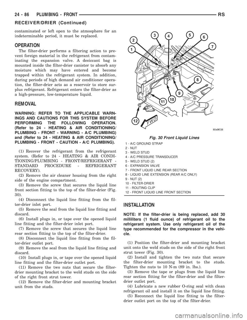
(3) Remove the screw that secures the liquid line
front section fitting to the top of the filter-drier (Fig.
30).
(4) Disconnect the liquid line fitting from the fil-
ter-drier inlet port.
(5) Remove the seal from the liquid line fitting and
discard.
(6) Install plugs in, or tape over the opened liquid
line fitting and the filter-drier inlet port.
(7) Remove the screw that secures the liquid line
rear section fitting to the top of the filter-drier.
(8) Disconnect the liquid line fitting from the fil-
ter-drier outlet port.
(9) Remove the seal from the liquid line fitting and
discard.
(10) Install plugs in, or tape over the opened liquid
line fitting and the filter-drier outlet port.
(11) Remove the two nuts that secure the filter-
drier mounting bracket to the weld studs on the side
of the right front strut tower.
(12) Remove the filter-drier and mounting bracket
unit from the studs.
INSTALLATION
NOTE: If the filter-drier is being replaced, add 30
milliliters (1 fluid ounce) of refrigerant oil to the
refrigerant system. Use only refrigerant oil of the
type recommended for the compressor in the vehi-
cle.
(1) Position the filter-drier and mounting bracket
unit onto the weld studs on the side of the right front
strut tower (Fig. 30).
(2) Install and tighten the two nuts that secure
the filter-drier mounting bracket to the studs.
Tighten the nuts to 10 N´m (89 in. lbs.).
(3) Remove the tape or plugs from the liquid line
rear section fitting for the filter-drier and the filter-
drier outlet port.
(4) Lubricate a new rubber O-ring seal with clean
refrigerant oil and install it on the liquid line fitting.
(5) Reconnect the liquid line fitting to the filter-
drier outlet port on the top of the filter-drier.
Fig. 30 Front Liquid Lines
1 - A/C GROUND STRAP
2 - NUT
3 - WELD STUD
4 - A/C PRESSURE TRANSDUCER
5 - WELD STUD (2)
6 - EXPANSION VALVE
7 - FRONT LIQUID LINE REAR SECTION
8 - LIQUID LINE EXTENSION (REAR A/C ONLY)
9 - NUT (2)
10 - FILTER-DRIER
11 - ROUTING CLIP
12 - FRONT LIQUID LINE FRONT SECTION
24 - 86 PLUMBING - FRONTRS
RECEIVER/DRIER (Continued)