2001 CHRYSLER VOYAGER parking brake
[x] Cancel search: parking brakePage 57 of 4284
defined as the amount of time from the start of a
wipe to the beginning of the next wipe. The rear
wiper system delay time is based on the following:
7.75 - (MPH x .05) = Seconds delay
Examples:
At zero (0) MPH the delay is 7.75 seconds.
At 100 MPH the delay is 2.75 seconds.
3.21.8 WIPE AFTER WASH
When the driver presses the wash button for over
1.5 seconds and releases it, the wiper will continue
to run for 2 additional wipe cycles.
3.22 USING THE DRBIIIT
Refer to the DRBIIItuser guide for instructions
and assistance with reading trouble codes, erasing
trouble codes, and other DRBIIItfunctions.
3.22.1 DRBIIITERROR MESSAGES
Under normal operation, the DRBIIItwill dis-
play one of only two error messages: user-requested
WARM Boot or User-Requested COLD Boot. If the
DRBIIItshould display any other error message,
record the entire display and call the STAR Center.
This is a sample of such an error message display:
ver:2.14
date: 26 Jul93
file: key_iff.cc
date: Jul26 1993
line: 548
err: 0xi
User-Requested COLD Boot
Press MORE to switch between this display
and the application screen.
Press F4 when done noting information.
3.22.2 DRBIIITDOES NOT POWER UP
(BLANK SCREEN)
If the LED's do not light or no sound is emitted at
start up, check for loose cable connections or a bad
cable. Check the vehicle battery voltage (data link
connector cavity 16). A minimum of 11 volts is
required to adequately power the DRBIIIt. Check
for proper grounds at DLC cavities 4 and 5.
If all connections are proper between the
DRBIIItand the vehicle or other devices, and the
vehicle battery is fully charged, an inoperative
DRBIIItmay be the result or a faulty cable or
vehicle wiring.
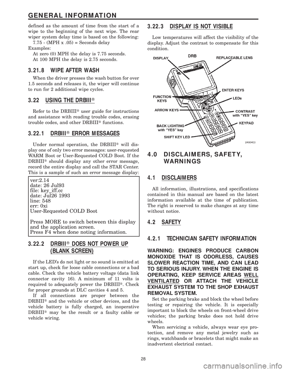
3.22.3 DISPLAY IS NOT VISIBLE
Low temperatures will affect the visibility of the
display. Adjust the contrast to compensate for this
condition.
4.0 DISCLAIMERS, SAFETY,
WARNINGS
4.1 DISCLAIMERS
All information, illustrations, and specifications
contained in this manual are based on the latest
information available at the time of publication.
The right is reserved to make changes at any time
without notice.
4.2 SAFETY
4.2.1 TECHNICIAN SAFETY INFORMATION
WARNING: ENGINES PRODUCE CARBON
MONOXIDE THAT IS ODORLESS, CAUSES
SLOWER REACTION TIME, AND CAN LEAD
TO SERIOUS INJURY. WHEN THE ENGINE IS
OPERATING, KEEP SERVICE AREAS WELL
VENTILATED OR ATTACH THE VEHICLE
EXHAUST SYSTEM TO THE SHOP EXHAUST
REMOVAL SYSTEM.
Set the parking brake and block the wheel before
testing or repairing the vehicle. It is especially
important to block the wheels on front-wheel drive
vehicles; the parking brake does not hold drive
wheels.
When servicing a vehicle, always wear eye pro-
tection, and remove any metal jewelry such as
rings, watchbands or bracelets that might make an
inadvertent electrical contact.
28
GENERAL INFORMATION
Page 1159 of 4284
The cycling of the build and decay valves is
similar to the ABS except that they work to control
wheel spin by applying brakes. ABS function is to
control wheel skid by releasing brakes.
Two pressure relief valves allow excess fluid vol-
ume to return to the reservoir when not used by the
build/decay cycles. These are required because the
pump supplies more volume than the traction con-
trol system requires.
If at any time the brake pedal is applied during a
traction control cycle, the brake lamp switch will
trigger the CAB to switch off the traction control.
The traction control system will be enabled at
each ignition cycle. It may be turned off by depress-
ing the Traction Control Switch. The traction con-
trol system function lamp will illuminate ªTRAC
OFFº immediately upon depressing the traction
control switch button. Only the ªTRACº portion of
the ªTRAC OFFº indicator will illuminate during a
traction control event. If the CAB calculates that
the brake temperatures are high, the traction con-
trol system will become inoperative until a time-out
period has elapsed. When in this thermal protection
mode, the traction control ªTRAC OFFº lamp will
illuminate; however, a fault will not be registered.
3.3 SYSTEM COMPONENTS
²controller antilock brake (CAB)
²vacuum booster
²master cylinder
²ABS integrated electronic control module/
hydraulic control unit (HCU), valve block assem-
bly: 8 valve solenoids (4 inlet valves, 4 outlet
valves, 2 accumulators) 1 motor, 2 pump
²ABS integrated electronic control module with
traction control same as above but has 10 valve
solenoids.
²4 wheel speed sensor/tone wheel assemblies
²ABS warning indicator
²fuses and wiring harness
²fluid reservoir
²TRAC/TRAC OFF indicator
3.3.1 ABS AND BRAKE WARNING
INDICATORS
The amber ABS warning indicator is located in
the instrument cluster. It is used to inform the
driver that the antilock function has been turned
off. The ABS warning indicator is controlled by the
CAB. The CAB controls the lamp with a command
over the PCI bus.
The ABS Warning Indicator will remain lit during
every key cycle until a circuit or component fault is
repaired and the CAB no longer detects the fault.After repair of a sensor signal fault or a pump motor
fault, the CAB must sense all four wheels at 25
km/h (15 mph) before it will extinguish the ABS and
TRAC OFF Indicators.
The Instrument Cluster will illuminate the ABS
Warning Indicator if it loses communication with
the CAB.
The red BRAKE warning indicator is also located
in the instrument cluster. It can be activated in
several ways. Application of the parking brake or a
low fluid signal from the fluid level switch located in
the master cylinder reservoir will cause the indica-
tor to come on.
3.3.2 CONTROLLER ANTILOCK BRAKE
(CAB)
The Controller Antilock Brake (CAB) is a
microprocessor-based device that monitors wheel
speeds and controls the antilock functions. The
CAB contains two microprocessors that receive
identical sensor signals and then independently
process the information. The results are then com-
pared to make sure that they agree. Otherwise, the
CAB will turn off the antilock and turn on the ABS
amber warning indicator.
The primary functions of the CAB are to:
²detect wheel locking tendencies
²control fluid pressure modulation to the brakes
during antilock stop
²monitor the system for proper operation
²manage traction control functions
²provide communication to the DRBIIItwhile in
diagnostic mode
²store diagnostic information in non-volatile memory
The CAB continuously monitors the speed of each
wheel. When a wheel locking tendency is detected,
the CAB will command the appropriate valve to
modulate brake fluid pressure in its hydraulic unit.
Brake pedal position is maintained during an an-
tilock stop by being a closed system with the use of
2 accumulators. The CAB continues to control pres-
sure in individual hydraulic circuits until a wheel
locking tendency is no longer present. The CAB
turns on the pump motor during an antilock stop.
The antilock brake system is constantly moni-
tored by the CAB for proper operation. If the CAB
detects a system malfunction, it can disable the
antilock system and turn on the ABS warning
indicator. If the antilock function is disabled, the
system will revert to standard base brake system
operation.
The CAB inputs include the following:
²diagnostic communication
²four wheel speed sensors
2
GENERAL INFORMATION
Page 1162 of 4284
4.0 DISCLAIMERS, SAFETY,
WARNINGS
4.1 DISCLAIMERS
All information, illustrations, and specifications
contained in this manual are based on the latest
information available at the time of publication.
The right is reserved to make changes at any time
without notice.
4.2 SAFETY
4.2.1 TECHNICIAN SAFETY INFORMATION
WARNING: ENGINES PRODUCE CARBON
MONOXIDE THAT IS ODORLESS, CAUSES
SLOWER REACTION TIME, AND CAN LEAD
TO SERIOUS INJURY. WHEN THE ENGINE IS
OPERATING, KEEP SERVICE AREAS WELL
VENTILATED OR ATTACH THE VEHICLE
EXHAUST SYSTEM TO THE SHOP EXHAUST
REMOVAL SYSTEM.
Set the parking brake and block the wheels before
testing or repairing the vehicle. It is especially
important to block the wheels on front-wheel drive
vehicles; the parking brake does not hold the drive
wheels.
When servicing a vehicle, always wear eye pro-
tection, and remove any metal jewelry such as
rings, watchbands or bracelets that might make an
inadvertent electrical contact.
When diagnosing a chassis problem, it is impor-
tant to follow approved procedures where applica-
ble. These procedures can be found in the service
manual. Following these procedures is very impor-
tant to the safety of individuals performing diag-
nostic tests.
4.2.2 VEHICLE PREPARATION FOR
TESTING
Make sure the vehicle being tested has a fully
charged battery. If is does not, false diagnostic codes
or error messages may occur.
4.2.3 SERVICING SUB-ASSEMBLIES
Some components of the chassis system are in-
tended to be serviced as an assembly only. Attempt-
ing to remove or repair certain system sub-
components may result in personal injury and/or
improper system operation. Only those components
with approved repair and installation procedures in
the service manual should be serviced.
4.2.4 DRBIIITSAFETY INFORMATION
WARNING: EXCEEDING THE LIMITS OF THE
DRB MULTIMETER IS DANGEROUS. IT CAN
EXPOSE YOU TO SERIOUS OR POSSIBLY
FATAL INJURY. CAREFULLY READ AND
UNDERSTAND THE CAUTIONS AND THE
SPECIFICATION LIMITS.
²Follow the vehicle manufacturer 's service speci-
fications at all times.
²Do not use the DRBIIItif it has been damaged.
²Do not use the test leads if the insulation is
damaged or if metal is exposed.
²To avoid electrical shock, do not touch the test
leads, tips, or the circuit being tested.
²Choose the proper range and functions for the
measurement. Do not try voltage or current mea-
surements that may exceed the rated capacity.
²Do not exceed the limits shown in the table below:
FUNCTION INPUT LIMIT
Volts 0 - 500 peak volts AC
0 - 500 volts DC
Ohms (resistance)* 0 -1.12 megohms
Frequency Measured
Frequency Generated0-10kHz
Temperature -58 - 1100ÉF
-50 - 600ÉC
* Ohms cannot be measured if voltage is present.
Ohms can be measured only in a non-powered
circuit.
²Voltage between any terminal and ground must
not exceed 500v DC or 500v peak AC.
²Use caution when measuring voltage above 25v
DC or 25v AC.
²Use the low current shunt to measure circuits up
to 10A. Use the high current clamp to measure
circuits exceeding 10A.
²When testing for the presence of voltage or cur-
rent, make sure the meter is functioning cor-
rectly. Take a reading of a known voltage or
current before accepting a zero reading.
²When measuring current, connect the meter in
series with the load.
²Disconnect the live test lead before disconnecting
the common test lead.
²When using the meter function, keep the
DRBIIItaway from spark plug or coil wires to
avoid measuring error from outside interference.
5
GENERAL INFORMATION
Page 1226 of 4284
4.0 DISCLAIMERS, SAFETY,
WARNINGS
4.1 DISCLAIMERS
All information, illustrations, and specifications
contained in this manual are based on the latest
information available at the time of publication.
The right is reserved to make changes at any time
without notice.
4.2 SAFETY
4.2.1 TECHNICIAN SAFETY INFORMATION
WARNING: ENGINES PRODUCE CARBON
MONOXIDE THAT IS ODORLESS, CAUSES
SLOWER REACTION TIME, AND CAN LEAD
TO SERIOUS INJURY. WHEN THE ENGINE IS
OPERATING, KEEP SERVICE AREAS WELL
VENTILATED OR ATTACH THE VEHICLE
EXHAUST SYSTEM TO THE SHOP EXHAUST
REMOVAL SYSTEM.
Set the parking brake and block the wheels before
testing or repairing the vehicle. It is especially
important to block the wheels on front wheel drive
vehicles; the parking brake does not hold the drive
wheels.
When servicing a vehicle, always wear eye pro-
tection, and remove any metal jewelry such as
watchbands or bracelets that might make electrical
contact.
When diagnosing a powertrain system problem,
it is important to follow approved procedures where
applicable. These procedures can be found in the
service manual. Following these procedures is very
important to the safety of individuals performing
diagnostic tests.
4.2.2 VEHICLE PREPARATION FOR
TESTING
Make sure the vehicle being tested has a fully
charged battery. If it does not, false diagnostic codes
or error messages may occur.
4.2.3 SERVICING SUB-ASSEMBLIES
Some components of the powertrain system are
intended to be serviced as an assembly only. At-
tempting to remove or repair certain system sub-
components may result in personal injury and/or
improper system operation. Only those components
with approved repair and installation procedures in
the service manual should be serviced.
4.2.4 DRBIIITSAFETY INFORMATION
WARNING: EXCEEDING THE LIMITS OF THE
DRBIIITMULTIMETER IS DANGEROUS. IT
CAN EXPOSE YOU TO SERIOUS OR
POSSIBLY FATAL INJURY. CAREFULLY
READ AND UNDERSTAND THE CAUTIONS
AND SPECIFICATION LIMITS.
Follow the vehicle manufacturer 's service specifi-
cations at all times.
²Do not use the DRBIIItif it has been damaged.
²Do not use the test leads if the insulation is
damaged or if metal is exposed.
²To avoid electrical shock, do not touch the test
leads, tip or the circuit being tested.
²Choose the proper range and function for the
measurement. Do not try voltage or current mea-
surements that may exceed the rated capacity.
²Do not exceed the limits shown in the table below:
FUNCTION INPUT LIMIT
Volts 0-500 peak volts AC
0-500 volts DC
Ohms (Resistance)* 0-1.12 megohms
Frequency Measure
Frequency Generated0-10 kHz
Temperature -58 - +1100ÉF
-50 - +600ÉC
* Ohms cannot be measured if voltage is present.
Ohms can be measured only in a non-powered
circuit.
²Voltage between any terminal and ground must
not exceed 500v DC or 500v peak AC.
²Use caution when measuring voltage above 25v
DC or 25v AC.
²The circuit being tested must be protected by a 10
amp fuse or circuit breaker.
²Use the low current shunt to measure circuits up
to 10 amps. Use the high current shunt to mea-
sure circuits exceeding 10 amps.
²When testing for the presence of voltage or cur-
rent, make sure the meter is functioning cor-
rectly. Take a reading of a known voltage or
current before accepting a zero reading.
²When measuring current, connect the meter in
series with the load.
²Disconnect the live test lead before disconnecting
the common test lead.
7
GENERAL INFORMATION
Page 1419 of 4284
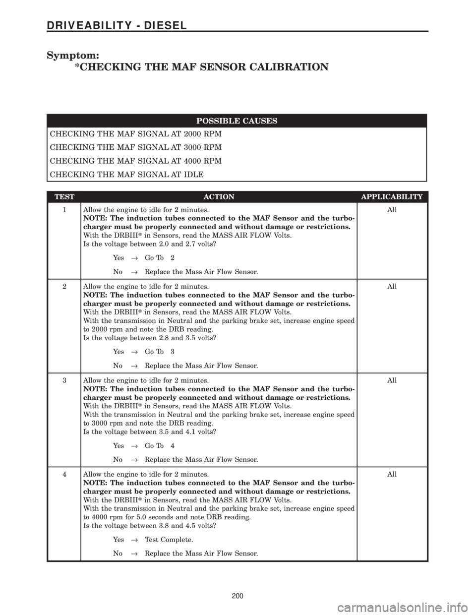
Symptom:
*CHECKING THE MAF SENSOR CALIBRATION
POSSIBLE CAUSES
CHECKING THE MAF SIGNAL AT 2000 RPM
CHECKING THE MAF SIGNAL AT 3000 RPM
CHECKING THE MAF SIGNAL AT 4000 RPM
CHECKING THE MAF SIGNAL AT IDLE
TEST ACTION APPLICABILITY
1 Allow the engine to idle for 2 minutes.
NOTE: The induction tubes connected to the MAF Sensor and the turbo-
charger must be properly connected and without damage or restrictions.
With the DRBIIItin Sensors, read the MASS AIR FLOW Volts.
Is the voltage between 2.0 and 2.7 volts?All
Ye s®Go To 2
No®Replace the Mass Air Flow Sensor.
2 Allow the engine to idle for 2 minutes.
NOTE: The induction tubes connected to the MAF Sensor and the turbo-
charger must be properly connected and without damage or restrictions.
With the DRBIIItin Sensors, read the MASS AIR FLOW Volts.
With the transmission in Neutral and the parking brake set, increase engine speed
to 2000 rpm and note the DRB reading.
Is the voltage between 2.8 and 3.5 volts?All
Ye s®Go To 3
No®Replace the Mass Air Flow Sensor.
3 Allow the engine to idle for 2 minutes.
NOTE: The induction tubes connected to the MAF Sensor and the turbo-
charger must be properly connected and without damage or restrictions.
With the DRBIIItin Sensors, read the MASS AIR FLOW Volts.
With the transmission in Neutral and the parking brake set, increase engine speed
to 3000 rpm and note the DRB reading.
Is the voltage between 3.5 and 4.1 volts?All
Ye s®Go To 4
No®Replace the Mass Air Flow Sensor.
4 Allow the engine to idle for 2 minutes.
NOTE: The induction tubes connected to the MAF Sensor and the turbo-
charger must be properly connected and without damage or restrictions.
With the DRBIIItin Sensors, read the MASS AIR FLOW Volts.
With the transmission in Neutral and the parking brake set, increase engine speed
to 4000 rpm for 5.0 seconds and note DRB reading.
Is the voltage between 3.8 and 4.5 volts?All
Ye s®Test Complete.
No®Replace the Mass Air Flow Sensor.
200
DRIVEABILITY - DIESEL
Page 1473 of 4284
FASTENER IDENTIFICATION
DESCRIPTION
The SAE bolt strength grades range from grade 2
to grade 8. The higher the grade number, the greater
the bolt strength. Identification is determined by the
line marks on the top of each bolt head. The actual
bolt strength grade corresponds to the number of line
marks plus 2. The most commonly used metric bolt
strength classes are 9.8 and 10.9. The metric
strength class identification number is imprinted on
the head of the bolt. The higher the class number,
the greater the bolt strength. Some metric nuts are
imprinted with a single-digit strength class on the
nut face. Refer to the Fastener Identification and
Fastener Strength Charts.
FASTENER USAGE
DESCRIPTION - FASTENER USAGE
WARNING: USE OF AN INCORRECT FASTENER
MAY RESULT IN COMPONENT DAMAGE OR PER-
SONAL INJURY.
Figure art, specifications and torque references in
this Service Manual are identified in metric and SAE
format.
During any maintenance or repair procedures, it is
important to salvage all fasteners (nuts, bolts, etc.)
for reassembly. If the fastener is not salvageable, a
fastener of equivalent specification must be used.
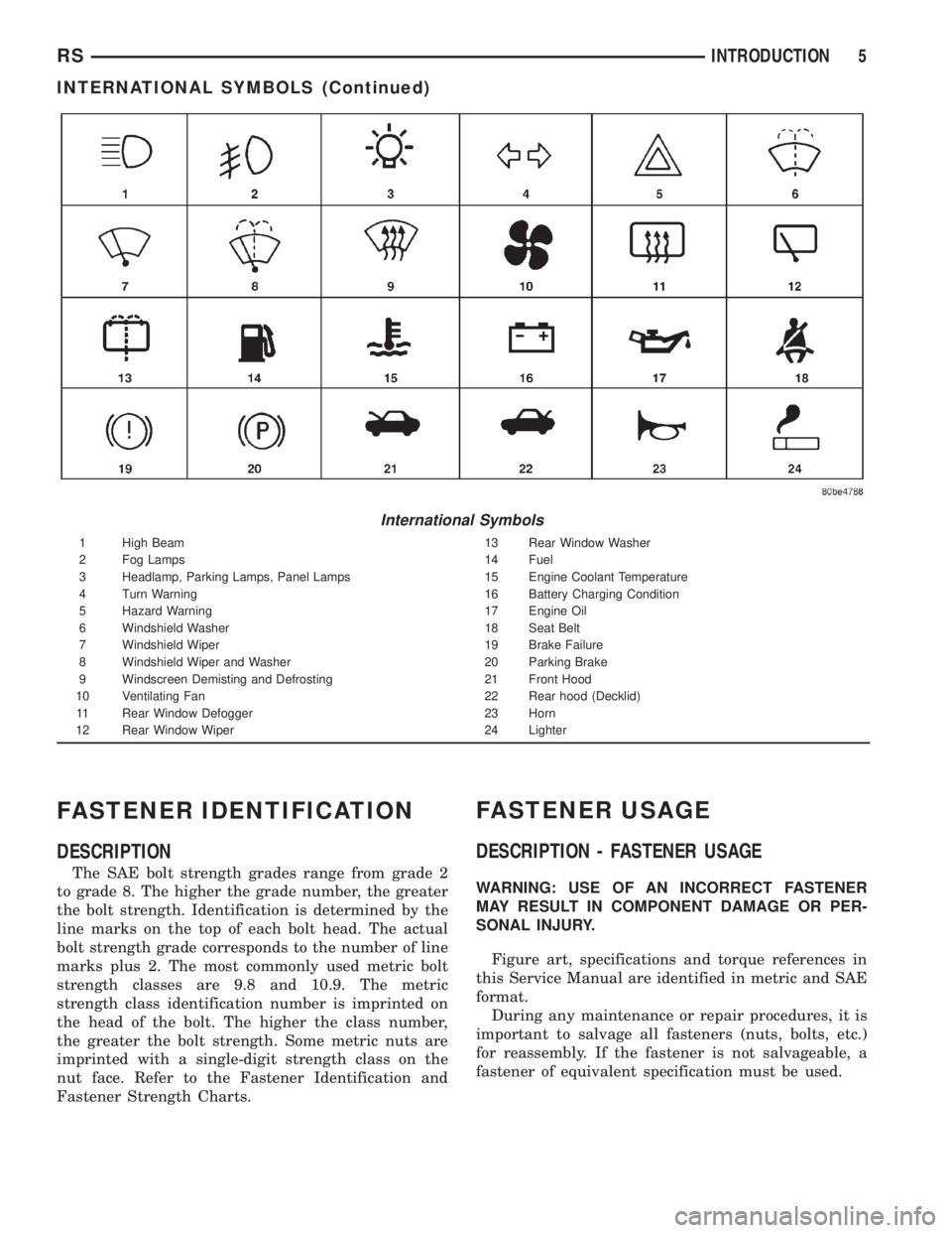
International Symbols
1 High Beam 13 Rear Window Washer
2 Fog Lamps 14 Fuel
3 Headlamp, Parking Lamps, Panel Lamps 15 Engine Coolant Temperature
4 Turn Warning 16 Battery Charging Condition
5 Hazard Warning 17 Engine Oil
6 Windshield Washer 18 Seat Belt
7 Windshield Wiper 19 Brake Failure
8 Windshield Wiper and Washer 20 Parking Brake
9 Windscreen Demisting and Defrosting 21 Front Hood
10 Ventilating Fan 22 Rear hood (Decklid)
11 Rear Window Defogger 23 Horn
12 Rear Window Wiper 24 Lighter
RSINTRODUCTION5
INTERNATIONAL SYMBOLS (Continued)
Page 1483 of 4284
FASTENER USAGE
DESCRIPTION
WARNING: USE OF AN INCORRECT FASTENER
MAY RESULT IN COMPONENT DAMAGE OR PER-
SONAL INJURY.
Figure art, specifications and torque references in
this Service Manual are identified in metric and SAE
format.
During any maintenance or repair procedures, it is
important to salvage all fasteners (nuts, bolts, etc.)
for reassembly. If the fastener is not salvageable, a
fastener of equivalent specification must be used.
THREADED HOLE REPAIR
DESCRIPTION
Most stripped threaded holes can be repaired using
a Helicoilt. Follow the vehicle or Helicoiltrecommen-
dations for application and repair procedures.
INTERNATIONAL VEHICLE
CONTROL & DISPLAY
SYMBOLS
DESCRIPTION
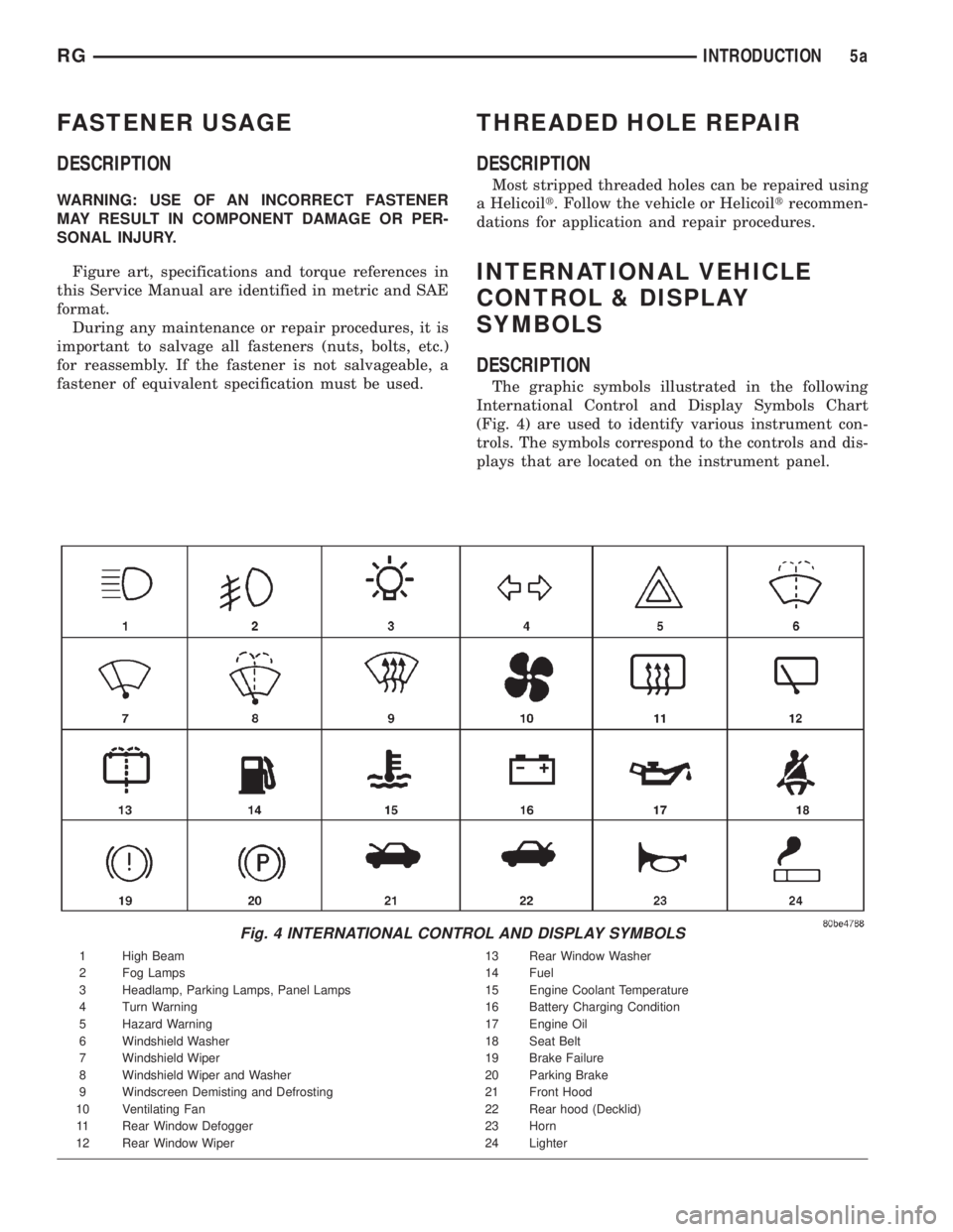
The graphic symbols illustrated in the following
International Control and Display Symbols Chart
(Fig. 4) are used to identify various instrument con-
trols. The symbols correspond to the controls and dis-
plays that are located on the instrument panel.
Fig. 4 INTERNATIONAL CONTROL AND DISPLAY SYMBOLS
1 High Beam 13 Rear Window Washer
2 Fog Lamps 14 Fuel
3 Headlamp, Parking Lamps, Panel Lamps 15 Engine Coolant Temperature
4 Turn Warning 16 Battery Charging Condition
5 Hazard Warning 17 Engine Oil
6 Windshield Washer 18 Seat Belt
7 Windshield Wiper 19 Brake Failure
8 Windshield Wiper and Washer 20 Parking Brake
9 Windscreen Demisting and Defrosting 21 Front Hood
10 Ventilating Fan 22 Rear hood (Decklid)
11 Rear Window Defogger 23 Horn
12 Rear Window Wiper 24 Lighter
RGINTRODUCTION5a
Page 1504 of 4284
Inspection and service should also be performed
anytime a malfunction is observed or suspected.
HOISTING
STANDARD PROCEDURE - HOISTING
Refer to Owner's Manual provided with vehicle for
proper emergency jacking procedures.
WARNING: THE HOISTING AND JACK LIFTING
POINTS PROVIDED ARE FOR A COMPLETE VEHI-
CLE. WHEN THE ENGINE OR REAR SUSPENSION
IS REMOVED FROM A VEHICLE, THE CENTER OF
GRAVITY IS ALTERED MAKING SOME HOISTING
CONDITIONS UNSTABLE. PROPERLY SUPPORT OR
SECURE VEHICLE TO HOISTING DEVICE WHEN
THESE CONDITIONS EXIST.
CAUTION: Do not position hoisting device on any
suspension component, including the front suspen-
sion crossmember, the rear leaf springs, and the
rear axle. Do not hoist on the front and rear
bumpers, the lower liftgate crossmember, the lower
radiator crossmember, the down standing flanges
on the sill or the front engine mount.
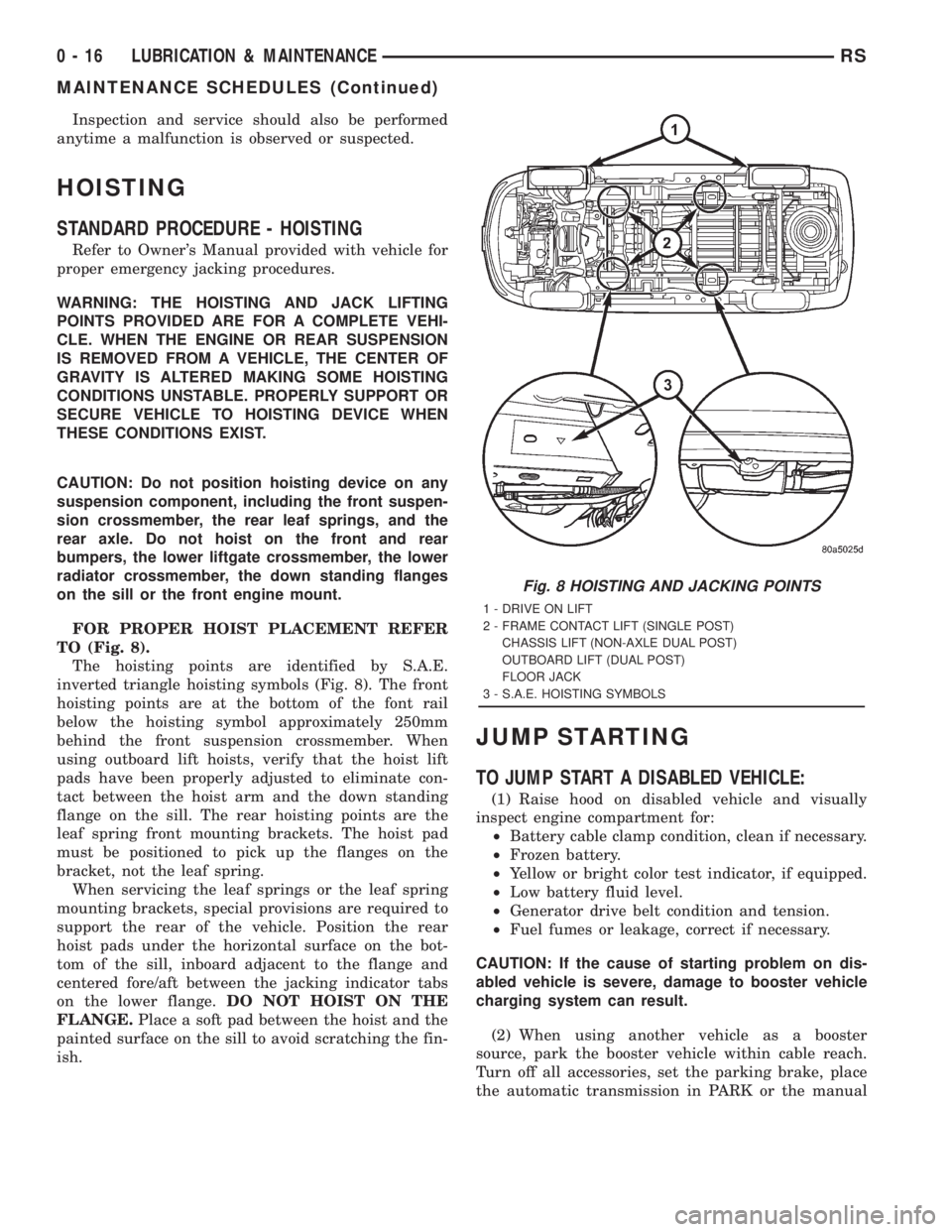
FOR PROPER HOIST PLACEMENT REFER
TO (Fig. 8).
The hoisting points are identified by S.A.E.
inverted triangle hoisting symbols (Fig. 8). The front
hoisting points are at the bottom of the font rail
below the hoisting symbol approximately 250mm
behind the front suspension crossmember. When
using outboard lift hoists, verify that the hoist lift
pads have been properly adjusted to eliminate con-
tact between the hoist arm and the down standing
flange on the sill. The rear hoisting points are the
leaf spring front mounting brackets. The hoist pad
must be positioned to pick up the flanges on the
bracket, not the leaf spring.
When servicing the leaf springs or the leaf spring
mounting brackets, special provisions are required to
support the rear of the vehicle. Position the rear
hoist pads under the horizontal surface on the bot-
tom of the sill, inboard adjacent to the flange and
centered fore/aft between the jacking indicator tabs
on the lower flange.DO NOT HOIST ON THE
FLANGE.Place a soft pad between the hoist and the
painted surface on the sill to avoid scratching the fin-
ish.
JUMP STARTING
TO JUMP START A DISABLED VEHICLE:
(1) Raise hood on disabled vehicle and visually
inspect engine compartment for:
²Battery cable clamp condition, clean if necessary.
²Frozen battery.
²Yellow or bright color test indicator, if equipped.
²Low battery fluid level.
²Generator drive belt condition and tension.
²Fuel fumes or leakage, correct if necessary.
CAUTION: If the cause of starting problem on dis-
abled vehicle is severe, damage to booster vehicle
charging system can result.
(2) When using another vehicle as a booster
source, park the booster vehicle within cable reach.
Turn off all accessories, set the parking brake, place
the automatic transmission in PARK or the manual
Fig. 8 HOISTING AND JACKING POINTS
1 - DRIVE ON LIFT
2 - FRAME CONTACT LIFT (SINGLE POST)
CHASSIS LIFT (NON-AXLE DUAL POST)
OUTBOARD LIFT (DUAL POST)
FLOOR JACK
3 - S.A.E. HOISTING SYMBOLS
0 - 16 LUBRICATION & MAINTENANCERS
MAINTENANCE SCHEDULES (Continued)