2001 CHRYSLER VOYAGER engine overheat
[x] Cancel search: engine overheatPage 49 of 4284

The DCHA assembly consists of a:
²combustion air fan assembly
²burner housing
²burner insert
²control unit/heat exchanger
²combustion chamber
²dosing pump
3.10.2.2 COMBUSTION AIR FAN
The combustion air fan assembly includes the:
²combustion air fan
²combustion air fan inlet
²fuel supply inlet
The combustion air fan delivers the air required
for combustion from the combustion air inlet to the
burner insert.
3.10.2.3 BURNER HOUSING
The burner housing includes the:
²coolant inlet
²coolant outlet
²exhaust outlet
The burner housing accommodates the burner
insert and is combined with the control unit/heat
exchanger as an assembly.
3.10.2.4 BURNER INSERT
The burner insert includes the:
²combustion pipe fuel cross section
²glow plug/flame sensor
Inside the burner insert fuel is distributed across
the combustion pipe fuel cross section. Combustion
of the fuel/air mixture takes place within the com-
bustion pipe to heat the exchanger. The glow plug/
flame sensor located in the burner insert ignites the
fuel/air mixture during heater start up. After heater
start up, the glow plug/flame sensor operates in the
flame sensor function. The glow plug/flame sensor
designed as an electrical resistor is located in the
burner insert opposite the flame side.
3.10.2.5 CONTROL UNIT/HEAT
EXCHANGER
The control unit/heat exchanger includes the:
²control unit
²temperature sensor
²overheat protection
²heat exchanger
²connector terminal
The control unit controls and monitors combus-
tion operation. The control unit is ventilated bymeans of a ventilation hose routed from the com-
bustion air collector compartment of the burner.
The heat exchanger transfers the heat generated by
combustion to the coolant circuit. The control unit/
heat exchanger and the burner housing are an
assembly and must not be disassembled.
The temperature sensor senses the coolant tem-
perature in the heat exchanger as an electrical
resistance. This signal is sent to the control unit for
processing.
The overheat protection, controlled by the tem-
perature resistor, protects the heater against undue
operating temperatures. The overheat protection
will switch the heater off if the water temperature
exceeds 105ÉC (221ÉF).
3.10.2.6 DOSING PUMP
The dosing pump is a combined delivery, dosing,
and shut-off system for the fuel supply of the heater.
The dosing pump receives its supply of fuel from the
vehicle's fuel tank.
3.10.3 OPERATION
3.10.3.1 ACTIVATION
When the ignition is in Run, the FCM monitors
the PCI bus for the Cabin Heater Activation re-
quest. The A/C ± Heater Control Module initiates
this request only when all conditions for Cabin
Heater activation are favorable (see below). The
request carries the status bit that the FCM requires
to activate its Cabin Heater Assist Control Output.
This output is a low side driver (coming from FCM
pin 15) which supplies a ground signal to the Cabin
Heater (pin 5). When the Cabin Heater receives this
ground signal input, it interprets this as an activa-
tion signal. The FCM low side driver is also capable
of diagnostic sensing. The driver will sense an open
circuit when the driver is off, and will sense a short
to voltage when the driver is on. The FCM will set
DTCs for both of these types of faults.
The DCHA will activate only when the:
²engine is running.
²coolant temperature is below 66ÉC (151ÉF).
²fuel tank has greater than 1/8 of a tank of fuel.
²Power switch on the A/C ± Heater Control Module
is on.
²Blend Control on the A/C ± Heater Control Mod-
ule is set above 95% reheat.
²Front Control Module (FCM) sees the Cabin
Heater Activation request that is bussed from the
A/C ± Heater Control Module.
When the DCHA starting sequence begins, the
glow plug and the combustion air fan are activated.
After 30 seconds, the fuel dosing pump begins oper-
20
GENERAL INFORMATION
Page 338 of 4284
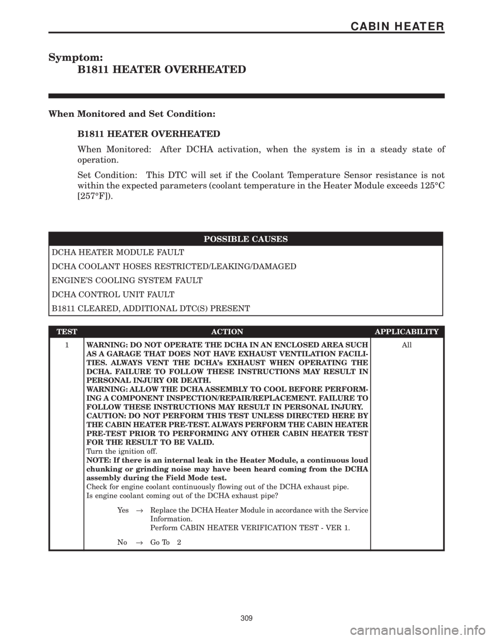
Symptom:
B1811 HEATER OVERHEATED
When Monitored and Set Condition:
B1811 HEATER OVERHEATED
When Monitored: After DCHA activation, when the system is in a steady state of
operation.
Set Condition: This DTC will set if the Coolant Temperature Sensor resistance is not
within the expected parameters (coolant temperature in the Heater Module exceeds 125ÉC
[257ÉF]).
POSSIBLE CAUSES
DCHA HEATER MODULE FAULT
DCHA COOLANT HOSES RESTRICTED/LEAKING/DAMAGED
ENGINE'S COOLING SYSTEM FAULT
DCHA CONTROL UNIT FAULT
B1811 CLEARED, ADDITIONAL DTC(S) PRESENT
TEST ACTION APPLICABILITY
1WARNING: DO NOT OPERATE THE DCHA IN AN ENCLOSED AREA SUCH
AS A GARAGE THAT DOES NOT HAVE EXHAUST VENTILATION FACILI-
TIES. ALWAYS VENT THE DCHA's EXHAUST WHEN OPERATING THE
DCHA. FAILURE TO FOLLOW THESE INSTRUCTIONS MAY RESULT IN
PERSONAL INJURY OR DEATH.
WARNING: ALLOW THE DCHA ASSEMBLY TO COOL BEFORE PERFORM-
ING A COMPONENT INSPECTION/REPAIR/REPLACEMENT. FAILURE TO
FOLLOW THESE INSTRUCTIONS MAY RESULT IN PERSONAL INJURY.
CAUTION: DO NOT PERFORM THIS TEST UNLESS DIRECTED HERE BY
THE CABIN HEATER PRE-TEST. ALWAYS PERFORM THE CABIN HEATER
PRE-TEST PRIOR TO PERFORMING ANY OTHER CABIN HEATER TEST
FOR THE RESULT TO BE VALID.
Turn the ignition off.
NOTE: If there is an internal leak in the Heater Module, a continuous loud
chunking or grinding noise may have been heard coming from the DCHA
assembly during the Field Mode test.
Check for engine coolant continuously flowing out of the DCHA exhaust pipe.
Is engine coolant coming out of the DCHA exhaust pipe?All
Ye s®Replace the DCHA Heater Module in accordance with the Service
Information.
Perform CABIN HEATER VERIFICATION TEST - VER 1.
No®Go To 2
309
CABIN HEATER
Page 339 of 4284
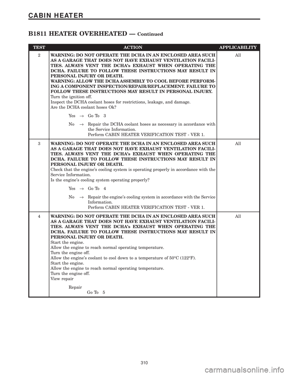
TEST ACTION APPLICABILITY
2WARNING: DO NOT OPERATE THE DCHA IN AN ENCLOSED AREA SUCH
AS A GARAGE THAT DOES NOT HAVE EXHAUST VENTILATION FACILI-
TIES. ALWAYS VENT THE DCHA's EXHAUST WHEN OPERATING THE
DCHA. FAILURE TO FOLLOW THESE INSTRUCTIONS MAY RESULT IN
PERSONAL INJURY OR DEATH.
WARNING: ALLOW THE DCHA ASSEMBLY TO COOL BEFORE PERFORM-
ING A COMPONENT INSPECTION/REPAIR/REPLACEMENT. FAILURE TO
FOLLOW THESE INSTRUCTIONS MAY RESULT IN PERSONAL INJURY.
Turn the ignition off.
Inspect the DCHA coolant hoses for restrictions, leakage, and damage.
Are the DCHA coolant hoses Ok?All
Ye s®Go To 3
No®Repair the DCHA coolant hoses as necessary in accordance with
the Service Information.
Perform CABIN HEATER VERIFICATION TEST - VER 1.
3WARNING: DO NOT OPERATE THE DCHA IN AN ENCLOSED AREA SUCH
AS A GARAGE THAT DOES NOT HAVE EXHAUST VENTILATION FACILI-
TIES. ALWAYS VENT THE DCHA's EXHAUST WHEN OPERATING THE
DCHA. FAILURE TO FOLLOW THESE INSTRUCTIONS MAY RESULT IN
PERSONAL INJURY OR DEATH.
Check that the engine's cooling system is operating properly in accordance with the
Service Information.
Is the engine's cooling system operating properly?All
Ye s®Go To 4
No®Repair the engine's cooling system in accordance with the Service
Information.
Perform CABIN HEATER VERIFICATION TEST - VER 1.
4WARNING: DO NOT OPERATE THE DCHA IN AN ENCLOSED AREA SUCH
AS A GARAGE THAT DOES NOT HAVE EXHAUST VENTILATION FACILI-
TIES. ALWAYS VENT THE DCHA's EXHAUST WHEN OPERATING THE
DCHA. FAILURE TO FOLLOW THESE INSTRUCTIONS MAY RESULT IN
PERSONAL INJURY OR DEATH.
Start the engine.
Allow the engine to reach normal operating temperature.
Turn the engine off.
Allow the engine's coolant to cool down to a temperature of 50ÉC (122ÉF).
Start the engine.
Allow the engine to reach normal operating temperature.
Turn the engine off.
View repairAll
Repair
Go To 5
310
CABIN HEATER
B1811 HEATER OVERHEATED ÐContinued
Page 340 of 4284
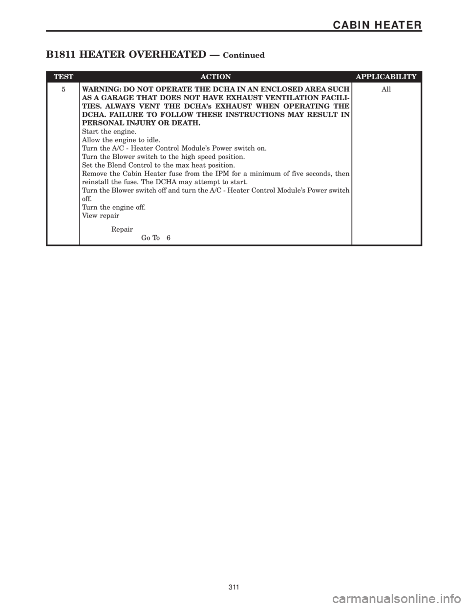
TEST ACTION APPLICABILITY
5WARNING: DO NOT OPERATE THE DCHA IN AN ENCLOSED AREA SUCH
AS A GARAGE THAT DOES NOT HAVE EXHAUST VENTILATION FACILI-
TIES. ALWAYS VENT THE DCHA's EXHAUST WHEN OPERATING THE
DCHA. FAILURE TO FOLLOW THESE INSTRUCTIONS MAY RESULT IN
PERSONAL INJURY OR DEATH.
Start the engine.
Allow the engine to idle.
Turn the A/C - Heater Control Module's Power switch on.
Turn the Blower switch to the high speed position.
Set the Blend Control to the max heat position.
Remove the Cabin Heater fuse from the IPM for a minimum of five seconds, then
reinstall the fuse. The DCHA may attempt to start.
Turn the Blower switch off and turn the A/C - Heater Control Module's Power switch
off.
Turn the engine off.
View repairAll
Repair
Go To 6
311
CABIN HEATER
B1811 HEATER OVERHEATED ÐContinued
Page 341 of 4284
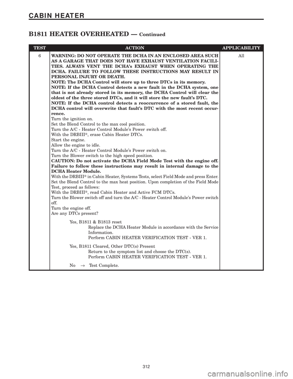
TEST ACTION APPLICABILITY
6WARNING: DO NOT OPERATE THE DCHA IN AN ENCLOSED AREA SUCH
AS A GARAGE THAT DOES NOT HAVE EXHAUST VENTILATION FACILI-
TIES. ALWAYS VENT THE DCHA's EXHAUST WHEN OPERATING THE
DCHA. FAILURE TO FOLLOW THESE INSTRUCTIONS MAY RESULT IN
PERSONAL INJURY OR DEATH.
NOTE: The DCHA Control will store up to three DTCs in its memory.
NOTE: If the DCHA Control detects a new fault in the DCHA system, one
that is not already stored in its memory, the DCHA Control will clear the
oldest of the three stored DTCs, and it will store the new fault's DTC.
NOTE: If the DCHA control detects a reoccurrence of a stored fault, the
DCHA control will overwrite that fault's DTC with the most recent occur-
rence.
Turn the ignition on.
Set the Blend Control to the max cool position.
Turn the A/C - Heater Control Module's Power switch off.
With the DRBIIIt, erase Cabin Heater DTCs.
Start the engine.
Allow the engine to idle.
Turn the A/C - Heater Control Module's Power switch on.
Turn the Blower switch to the high speed position.
CAUTION: Do not activate the DCHA Field Mode Test with the engine off.
Failure to follow these instructions may result in internal damage to the
DCHA Heater Module.
With the DRBIIItin Cabin Heater, Systems Tests, select Field Mode and press Enter.
Set the Blend Control to the max heat position. Upon completion of the Field Mode
Test, proceed as follows:
With the DRBIIIt, read Cabin Heater and Active FCM DTCs.
Turn the Blower switch off and turn the A/C - Heater Control Module's Power switch
off.
Turn the engine off.
Are any DTCs present?All
Yes, B1811 & B1813 reset
Replace the DCHA Heater Module in accordance with the Service
Information.
Perform CABIN HEATER VERIFICATION TEST - VER 1.
Yes, B1811 Cleared, Other DTC(s) Present
Return to the symptom list and choose the DTC(s).
Perform CABIN HEATER VERIFICATION TEST - VER 1.
No®Test Complete.
312
CABIN HEATER
B1811 HEATER OVERHEATED ÐContinued
Page 348 of 4284

TEST ACTION APPLICABILITY
1WARNING: DO NOT OPERATE THE DCHA IN AN ENCLOSED AREA SUCH
AS A GARAGE THAT DOES NOT HAVE EXHAUST VENTILATION FACILI-
TIES. ALWAYS VENT THE DCHA's EXHAUST WHEN OPERATING THE
DCHA. FAILURE TO FOLLOW THESE INSTRUCTIONS MAY RESULT IN
PERSONAL INJURY OR DEATH.
WARNING: ALLOW THE DCHA ASSEMBLY TO COOL BEFORE PERFORM-
ING A COMPONENT INSPECTION/REPAIR/REPLACEMENT. FAILURE TO
FOLLOW THESE INSTRUCTIONS MAY RESULT IN PERSONAL INJURY.
CAUTION: DO NOT PERFORM THIS TEST UNLESS DIRECTED HERE BY
THE CABIN HEATER PRE-TEST. ALWAYS PERFORM THE CABIN HEATER
PRE-TEST PRIOR TO PERFORMING ANY OTHER CABIN HEATER TEST
FOR THE RESULT TO BE VALID.
NOTE: If present, diagnose and repair DTC B1811 Heater Overheated and
any other conditions relating to overheating before diagnosing this DTC.
Turn the ignition off.
NOTE: Check connectors - Clean/repair as necessary.
Disconnect the Dosing Pump harness connector.
Turn the ignition on.
Set the Blend Control to the max cool position.
Turn the A/C - Heater Control Module's Power switch off.
With the DRBIIIt, erase Cabin Heater DTCs.
Start the engine.
Allow the engine to idle.
Turn the A/C - Heater Control Module's Power switch on.
Turn the Blower switch to the high speed position.
CAUTION: Do not activate the DCHA Field Mode Test with the engine off.
Failure to follow these instructions may result in internal damage to the
DCHA Heater Module.
NOTE: Do not disconnect the vehicle's battery or the DCHA's main power
supply while the DCHA is in operation or in run-down mode. Failure to
follow these instructions may result in excess emissions from the DCHA
during heater operation.
With the DRBIIItin Cabin Heater, Systems Tests, select Field Mode and press Enter.
Set the Blend Control to the max heat position. Upon completion of the Field Mode
Test, proceed as follows:
With the DRBIIIt, read Cabin Heater DTCs.
Turn the Blower switch off and turn the A/C - Heater Control Module's Power switch
off.
Turn the engine off.
Is DTC B1820 Dosing Pump Circuit: Short to Ground present?All
Ye s®Go To 2
No®Replace the Dosing Pump in accordance with the Service Infor-
mation.
Perform CABIN HEATER VERIFICATION TEST - VER 1.
319
CABIN HEATER
B1820 DOSING PUMP CIRCUIT: SHORT TO GROUND ÐContinued
Page 1221 of 4284
3.2.2 ECM OPERATING MODES
As input signals to the ECM change, the ECM
adjusts its response to the output devices. For
example, the ECM must calculate a different fuel
quantity and fuel timing for engine idle condition
than it would for a wide open throttle condition.
There are several different modes of operation that
determine how the ECM responds to the various
input signals.
Ignition Switch On (Engine Off)
When the ignition switch is turned on, the ECM
activates the glow plug relay for a time period that
is determined by engine coolant temperature, atmo-
spheric temperature and battery voltage. The ECM
also activates the lift pump to prime the fuel sys-
tem.
Engine Start-up Mode
The ECM uses the engine temperature sensor
and the crankshaft position sensor (engine speed)
inputs to determine fuel injection quantity.
Normal Driving Modes
Engine idle, warm-up, acceleration, deceleration
and wide open throttle modes are controlled based
on all of the sensor inputs to the ECM. The ECM
uses these sensor inputs to adjust fuel quantity and
fuel injector timing.
Overheat Protection Mode
If engine temperature is above 106É C (223É F)
and vehicle speed is above 40 km/h (25 MPH) the
ECM will activate the high speed fan and will limit
fuel quantity for engine protection.
Limp-In Mode
If there is a fault detected with the accelerator
pedal position sensor, the ECM will set the engine
speed at 1100 RPM.
Overspeed Detection Mode
If the ECM detects engine RPM that exceeds
5000 RPM, the ECM will set a DTC in memory and
limit engine RPM to no more that 2500 RPM until
the DTC(s) is cleared.
After-Run Mode
The ECM transfers RAM information to ROM
and performs an Input/Output state check.
3.2.3 MONITORED CIRCUITS
The ECM is able to monitor and identify most
driveability related trouble conditions. Some cir-
cuits are directly monitored through ECM feedback
circuitry. In addition, the ECM monitors the voltage
state of some circuits and compares those stateswith expected values. Other systems are monitored
indirectly when the ECM conducts a rationality test
to identify problems.
Although most subsystems of the engine control
module are either directly or indirectly monitored,
there may be occasions when diagnostic trouble
codes are not immediately identified. For a trouble
code to set, a specific set of conditions must occur
and unless these conditions occur, a DTC will not
set.
3.2.4 SKIS OVERIVEW
The sentry key immobilizer system (SKIS) is
designed to prevent unauthorized vehicle opera-
tion. The system consists of a sentry key immobi-
lizer module (SKIM), ignition key(s) equipped with
a transponder chip and the ECM. When the ignition
switch is turned on, the SKIM interrogates the
ignition key. If the ignition key is Valid or Invalid,
the SKIM sends a PCI Bus message to the ECM
indicating ignition key status. Upon receiving this
message the ECM will terminate engine operation
or allow the engine to continue to operate.
3.2.5 SKIS ON-BOARD DIAGNOSTICS
The sentry key immobilizer module (SKIM) has
been programmed to transmit and monitor many
different coded messages as well as PCI Bus mes-
sages. This monitoring is called On-Board Diagnos-
tics. Certain criteria must be met for a DTC to be
entered into SKIM memory. The criteria may be a
range of; input voltage, PCI Bus message or coded
messages to the SKIM. If all of the criteria for
monitoring a circuit or function are met and a fault
is detected, a DTC will be stored in the SKIM
memory.
3.2.6 SKIS OPERATION
When ignition power is supplied to the SKIM, the
SKIM performs an internal self-test. After the self-
test is complete, the SKIM energizes the antenna
(this activates the transponder chip) and sends a
challenge to the transponder chip. The transponder
chip responds to the challenge by generating an
encrypted response message using the following:
Secret Key - This is an electronically stored value
(identification number) that is unique to each SKIS.
The secret key is stored in the SKIM, ECM and all
ignition key transponders.
Challenge - This is a random number that is gen-
erated by the SKIM at each ignition key cycle.
The secret key and challenge are the two vari-
ables used in the algorithm that produces the
encrypted response message. The transponder uses
the crypto algorithm to receive, decode and respond
to the message sent by SKIM. After responding to
the coded message, the transponder sends a tran-
2
GENERAL INFORMATION
Page 1492 of 4284
CONTAINER IDENTIFICATION
Standard engine oil identification notations have
been adopted to aid in the proper selection of engine
oil. The identifying notations are located on the label
of engine oil plastic bottles and the top of engine oil
cans (Fig. 5).
This symbol on the front of an oil container means
that the oil has been certified by the American Petro-
leum Institute (API) to meet all the lubrication
requirements specified by DaimlerChrysler.
FLEXIBLE FUEL ENGINE OIL - 3.3L
Engine Oil Selection for Operating on E-85 Fuel
If vehicle operates on E-85 fuel either full or part-
time, use only MopartFlexible Fuel 5W-30 engine oil
or an equivalent that meets DaimlerChrysler Stan-
dard MS-9214. Equivalent commercial Flexible Fuel
engine oils may be labeled as Multi-Fuel, Variable
Fuel, Flexible Fuel, etc. These engine oils may be
satisfactory if they meet the DaimlerChrysler Stan-
dard.
SAE 5W-30 engine oil is preferred for use in Flex-
ible Fuel engines.
CAUTION: If Flexible Fuel engine oil is not used
when using E-85 fuel, engine wear or damage may
result.
DESCRIPTION - AUTOMATIC TRANSMISSION
FLUID
NOTE: Refer to the maintenance schedules for the
recommended maintenance (fluid/filter change)
intervals for this transaxle.
NOTE: For fluid level checking procedures, (Refer
to 21 - TRANSMISSION/TRANSAXLE/AUTOMATIC -
31TH/FLUID - STANDARD PROCEDURE) (Refer to 21
- TRANSMISSION/TRANSAXLE/AUTOMATIC - 41TE/
FLUID - STANDARD PROCEDURE)NOTE: The 41TE transaxle has a common transmis-
sion and differential sump. Filling the transaxle
accommodates the differential as well.
TRANSMISSION FLUID
MopartATF+4 (Automatic Transmission Fluid-
Type 9602) is required in this transaxle. Substitute
fluids can induce torque converter clutch shudder.
MopartATF+4 (Automatic Transmission Fluid-
Type 9602) when new is red in color. The ATF is dyed
red so it can be identified from other fluids used in
the vehicle such as engine oil or antifreeze. The red
color is not permanent and is not an indicator of fluid
condition. As the vehicle is driven, the ATF will begin
to look darker in color and may eventually become
brown.This is normal.A dark brown/black fluid
accompanied with a burnt odor and/or deterioration
in shift quality may indicate fluid deterioration or
transmission component failure.
FLUID ADDITIVES
DaimlerChrysler strongly recommends against the
addition of any fluids to the transmission, other than
those automatic transmission fluids listed above.
Exceptions to this policy are the use of special dyes
to aid in detecting fluid leaks.
Various ªspecialº additives and supplements exist
that claim to improve shift feel and/or quality. These
additives and others also claim to improve converter
clutch operation and inhibit overheating, oxidation,
varnish, and sludge. These claims have not been sup-
ported to the satisfaction of DaimlerChrysler and
these additivesmust not be used.The use of trans-
mission ªsealersº should also be avoided, since they
may adversely affect the integrity of transmission
seals.
DESCRIPTION - FUEL REQUIREMENTS
Your engine is designed to meet all emissions reg-
ulations and provide excellent fuel economy and per-
formance when using high quality unleaded gasoline
having an octane rating of 87. The use of premium
gasoline is not recommended. The use of premium
gasoline will provide no benefit over high quality reg-
ular gasoline, and in some circumstances may result
in poorer performance.
Light spark knock at low engine speeds is not
harmful to your engine. However, continued heavy
spark knock at high speeds can cause damage and
immediate service is required. Engine damage result-
ing from operation with a heavy spark knock may
not be covered by the new vehicle warranty.
Poor quality gasoline can cause problems such as
hard starting, stalling and hesitations. If you experi-
ence these symptoms, try another brand of gasoline
before considering service for the vehicle.
Fig. 5 Engine Oil Container Standard Notations
0 - 4 LUBRICATION & MAINTENANCERS
FLUID TYPES (Continued)