2001 CHRYSLER VOYAGER air filter
[x] Cancel search: air filterPage 46 of 4284
± Evap Temp Sensor Shorted
± Evap Temp Sensor Open
± A/C Pressure Too Low
± A/C Pressure Too High
± Invalid Conditions for Cooldown Test, Evap
Temperature Too Low
If a message other than Cooldown Test Passed
occurs, refer to the appropriate symptom for diag-
nosis.
3.9.1.7 ACTIVE AND STORED TROUBLE
CODES
The Automatic Temperature Control (ATC) is
capable of storing Active and Stored trouble codes.
Active codes indicate a current fault in the system.
Stored codes indicate that a problem has occurred
in the system, however is not currently present.
Active codes cannot be erased until the problem
causing the code has been repaired. At this time the
Active code is converted to a Stored code, which can
be erased using the DRBIIIt.
3.9.2 MANUAL TEMPERATURE CONTROL
3.9.2.1 SYSTEM AVAILABILITY
Depending on the model, either a Single-Zone Air
Conditioning System or a Dual-Zone Air Condition-
ing System is currently available in these vehicles.
3.9.2.2 CABIN HEATER
For Vehicles equipped with a diesel engine, a
Cabin Heater is used in conjunction with the HVAC
system. The Cabin Heater is designed to supply the
vehicle's occupants with heat prior to the engine
reaching operating temperature. For additional in-
formation on this system, refer to Cabin Heater
under General Information and Diagnostic Proce-
dures in this manual.
3.9.2.3 ZONE CONTROL ± SINGLE-ZONE
The Single-Zone Air Conditioning System main-
tains incoming air temperature, airflow, fan speed,
and fresh air intake for the entire vehicle from the
instrument panel mounted A/C ± Heater Control
Module. The full range of temperature that the
system can produce in any mode for the entire
vehicle is available by positioning the blend control
to the desired range.
3.9.2.4 ZONE CONTROL ± DUAL-ZONE
The Dual-Zone Air Conditioning System main-
tains incoming air temperature, airflow, fan speed,
and fresh air intake for the entire vehicle from the
instrument panel mounted A/C ± Heater ControlModule. In addition, this system provides com-
pletely independent side-to-side control of incoming
air temperature. The full range of temperature that
the system can produce in any mode is available on
either side of the vehicle by positioning the inde-
pendent driver and passenger blend controls to the
desired range.
3.9.2.5 AIR DISTRIBUTION
The HVAC unit has five fully adjustable instru-
ment panel outlets. Side-window demister outlets
in the instrument panel eliminate door ducts and
door-to-instrument panel seals. A single, central
mounted outlet delivers air for defrosting the wind-
shield. Air exhausters allow air entering at the
front of the vehicle to flow out the back to the rear
occupants. Mid-cabin comfort control directs only
cooling air flow to the intermediate seat occupants
through outlets at the rear of each front door trim
panel. Air is supplied to these outlets from the
instrument panel through ducts in the doors that
use molded seals at the instrument panel to prevent
air leakage. Wide outlets under the front seats with
directional dividers distribute heated air across the
floor to the intermediate seat occupants. Ducts in
the center of the vehicle under the carpet deliver air
from the HVAC unit to these outlets. Models
equipped with Dual-Zone A/C systems also include
a dust and odor air filter installed in the HAVC
housing.
3.9.2.6 DOOR ACTUATORS
The electric door actuators are a two-wire design.
Each door actuator uses a similar connector wired
directly to the A/C ± Heater Control Module. Single-
Zone systems have one blend door actuator, one
mode door actuator, and one recirculation door
actuator. Dual-Zone systems have two blend door
actuators, one mode door actuator, and one recircu-
lation door actuator. All of the door actuators are
accessible from the vehicle's interior.
3.9.2.7 DOOR ACTUATOR CONTROL
The A/C ± Heater Control Module knows the
number of operating actuator revolutions required
for full door travel as well as the number of actuator
commutator pulses per revolution. Using these pa-
rameters, the A/C ± Heater Control Module runs
the actuator for the number of commutator pulses
that correspond to the desired door position. To
maintain accuracy, the system recalibrates itself
periodically at known zero and full travel condi-
tions.
17
GENERAL INFORMATION
Page 1021 of 4284
MEMORY SYSTEM VERIFICATION TEST - VER 1 APPLICABILITY
1. Reconnect all previously disconnected components and connectors.
2. If any Memory Seat Memory Module Trouble Codes are present, erase at this time.
3. With the Memory Switch on the Driver's Door, program the Driver's Seat #1 Button to a
desired position and Driver #2 Button to a different position.
4. Remove the Ignition Key and close all Doors to allow the Body Control Module to time out,
about 30 seconds.
5. Verify that both Memory positions can be recalled from the RKE transmitter and the
Memory Switch on the Driver's Door.
6. Turn the ignition on, and with the DRBIII, erase all Diagnostic Trouble Codes from ALL
modules. Start the engine and allow it to run for 2 minutes and fully operate the system that
was malfunctioning.
7. Turn the ignition off and wait 5 seconds. Turn the ignition on and using the DRBIII, read
DTC's from ALL modules.
Are any DTC's present or is the original complaint still present?All
Ye s®Repair is not complete, refer to appropriate symptom.
No®Repair is complete.
POWERTRAIN VERIFICATION TEST VER - 1 APPLICABILITY
1. NOTE: If the PCM has been replaced and the correct VIN and mileage have not
been programmed, a DTC will be set in the ABS Module, Airbag Module and the
SKIM.
2. NOTE: If the vehicle is equipped with a Sentry Key Immobilizer System, Secret
Key data must be updated. Refer to the Service Information for the PCM, SKIM and
the Transponder (ignition key) for programming information.
3. Inspect the vehicle to ensure that all components related to the repair are connected
properly.
4. Inspect the engine oil for fuel contamination. Replace the oil and filter as necessary.
5. Attempt to start the engine.
6. If the No Start condition is still present, refer to the symptom list and perform the diagnostic
testing as necessary. refer to and Technical Service Bulletins that may apply.
7. Run the engine for one warm-up cycle to verify operation.
8. With the DRBIIIt, confirm that no DTCs or Secondary Indicators are present and that all
components are functioning properly.
9. If a DTC is present, refer to the appropriate category and select the corresponding symptom.
Are any DTCs present?All
Ye s®Repair is not complete, refer to appropriate symptom.
No®Repair is complete.
992
VERIFICATION TESTS
Verification Tests ÐContinued
Page 1376 of 4284
TEST ACTION APPLICABILITY
6 Refer to the appropriate Service Information and perform the Fuel Pressure Test.
NOTE: The following is a list of problems that can cause the fuel pressure to
become out of specification: restricted fuel filter or fuel lines, failed fuel
pressure solenoid, air in fuel system, failed fuel sending unit, gelled fuel,
faulty injector.
Is the fuel pressure within specification?All
Ye s®Replace the Fuel Pressure Sensor in accordance with the Service
Information.
No®Repair as necessary in accordance with the Service Information.
7WARNING: WHEN THE ENGINE IS OPERATING, DO NOT STAND IN A
DIRECT LINE WITH THE FAN. DO NOT PUT YOUR HANDS NEAR THE
PULLEYS, BELTS OR FAN. DO NOT WEAR LOOSE CLOTHING.
NOTE: The conditions that set the DTC are not present at this time. The
following list may help in identifying the intermittent condition.
With the engine running and at normal operating temperature, monitor the DRB
parameters related to the DTC while wiggling the wiring harness. Look for param-
eter values to change and/or a DTC to set.
Review the DTC When Monitored and Set Conditions. If possible, try to duplicate the
conditions under which the DTC was set.
Refer to any Technical Service Bulletins (TSB) that may apply.
Visually inspect the related wiring harness. Look for any chafed, pierced, pinched, or
partially broken wires.
Visually inspect the related wiring harness connectors. Look for broken, bent, pushed
out, or corroded terminals.
Were any of the above conditions present?All
Ye s®Repair as necessary.
No®Test Complete.
157
DRIVEABILITY - DIESEL
P1130-FUEL RAIL PRESSURE MALFUNCTION LEAKAGE DETECTED Ð
Continued
Page 1413 of 4284
Symptom:
*CHECKING THE ENGINE MECHANICAL SYSTEMS
POSSIBLE CAUSES
CHECKING ENGINE MECHANICAL SYSTEMS
TEST ACTION APPLICABILITY
1NOTE: The following items should be checked as a possible cause of a
Driveability or No-Start problem.
WARNING: Do not attempt to remove or separate high pressure fuel line.
Attempting to do so could result in severe bodily injury or death.
Engine Valve Timing - must be within specification
Engine Compression - must be within specifications
Camshaft Lobes - check for abnormal wear
Camshaft Position Sensor - check the camshaft position sensor tooth for debris and
deterioration
Crankshaft Position Sensor - check the crankshaft tone wheel for debris and
deterioration
Engine Exhaust System - must be free of any restriction
Engine Drive Sprocket - must be properly positioned
Power Brake Booster - must be free of any vacuum leaks
Fuel - must have adequate supply and must be free of contamination and gasoline
Fuel Injectors - must not be plugged or restricted
Fuel Injection Pump - must be producing the correct output volume and pressure
Inspect the Fuel Lines, Fuel Filter and Fuel Pressure Relief Valve for signs of
restriction and leaks
NOTE: Check for any Technical Service Bulletins that may relate to the
problem.
Are there any problems evident?All
Ye s®Repair as necessary.
Perform ROAD TEST VERIFICATION - VER-2.
No®Test Complete.
194
DRIVEABILITY - DIESEL
Page 1442 of 4284
Verification Tests
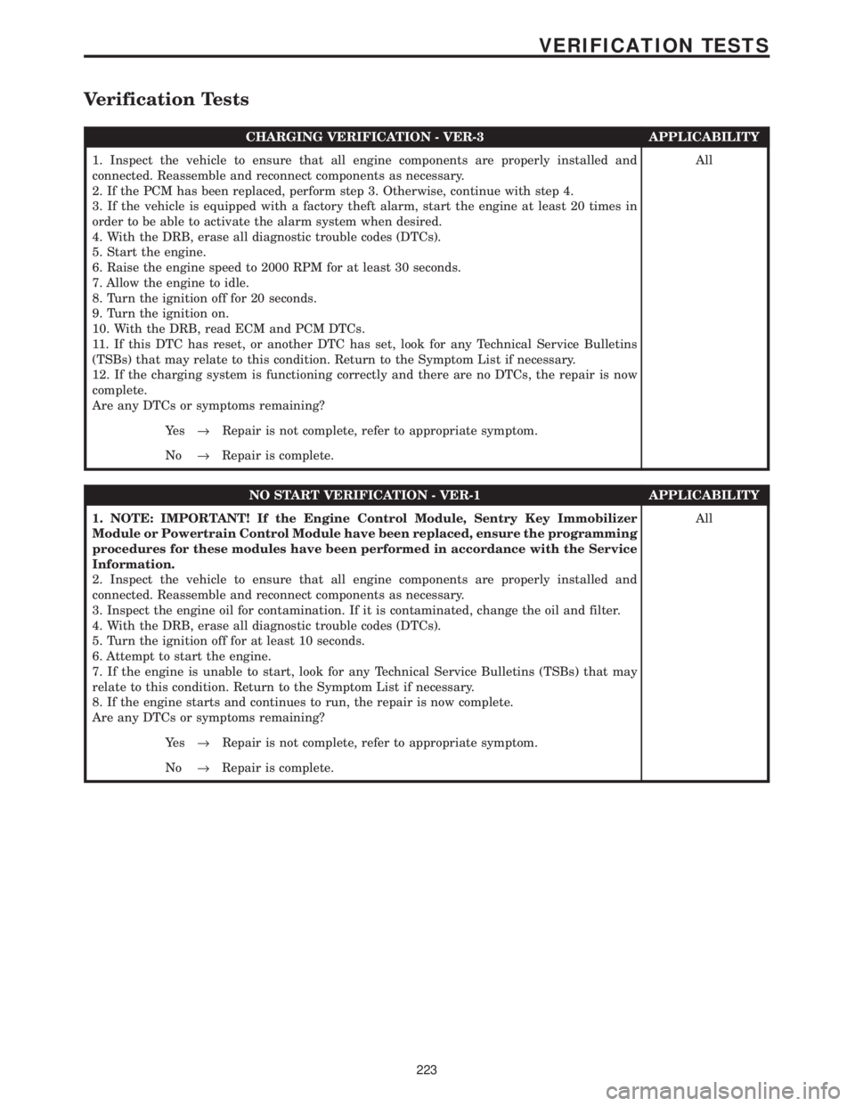
CHARGING VERIFICATION - VER-3 APPLICABILITY
1. Inspect the vehicle to ensure that all engine components are properly installed and
connected. Reassemble and reconnect components as necessary.
2. If the PCM has been replaced, perform step 3. Otherwise, continue with step 4.
3. If the vehicle is equipped with a factory theft alarm, start the engine at least 20 times in
order to be able to activate the alarm system when desired.
4. With the DRB, erase all diagnostic trouble codes (DTCs).
5. Start the engine.
6. Raise the engine speed to 2000 RPM for at least 30 seconds.
7. Allow the engine to idle.
8. Turn the ignition off for 20 seconds.
9. Turn the ignition on.
10. With the DRB, read ECM and PCM DTCs.
11. If this DTC has reset, or another DTC has set, look for any Technical Service Bulletins
(TSBs) that may relate to this condition. Return to the Symptom List if necessary.
12. If the charging system is functioning correctly and there are no DTCs, the repair is now
complete.
Are any DTCs or symptoms remaining?All
Ye s®Repair is not complete, refer to appropriate symptom.
No®Repair is complete.
NO START VERIFICATION - VER-1 APPLICABILITY
1. NOTE: IMPORTANT! If the Engine Control Module, Sentry Key Immobilizer
Module or Powertrain Control Module have been replaced, ensure the programming
procedures for these modules have been performed in accordance with the Service
Information.
2. Inspect the vehicle to ensure that all engine components are properly installed and
connected. Reassemble and reconnect components as necessary.
3. Inspect the engine oil for contamination. If it is contaminated, change the oil and filter.
4. With the DRB, erase all diagnostic trouble codes (DTCs).
5. Turn the ignition off for at least 10 seconds.
6. Attempt to start the engine.
7. If the engine is unable to start, look for any Technical Service Bulletins (TSBs) that may
relate to this condition. Return to the Symptom List if necessary.
8. If the engine starts and continues to run, the repair is now complete.
Are any DTCs or symptoms remaining?All
Ye s®Repair is not complete, refer to appropriate symptom.
No®Repair is complete.
223
VERIFICATION TESTS
Page 1495 of 4284
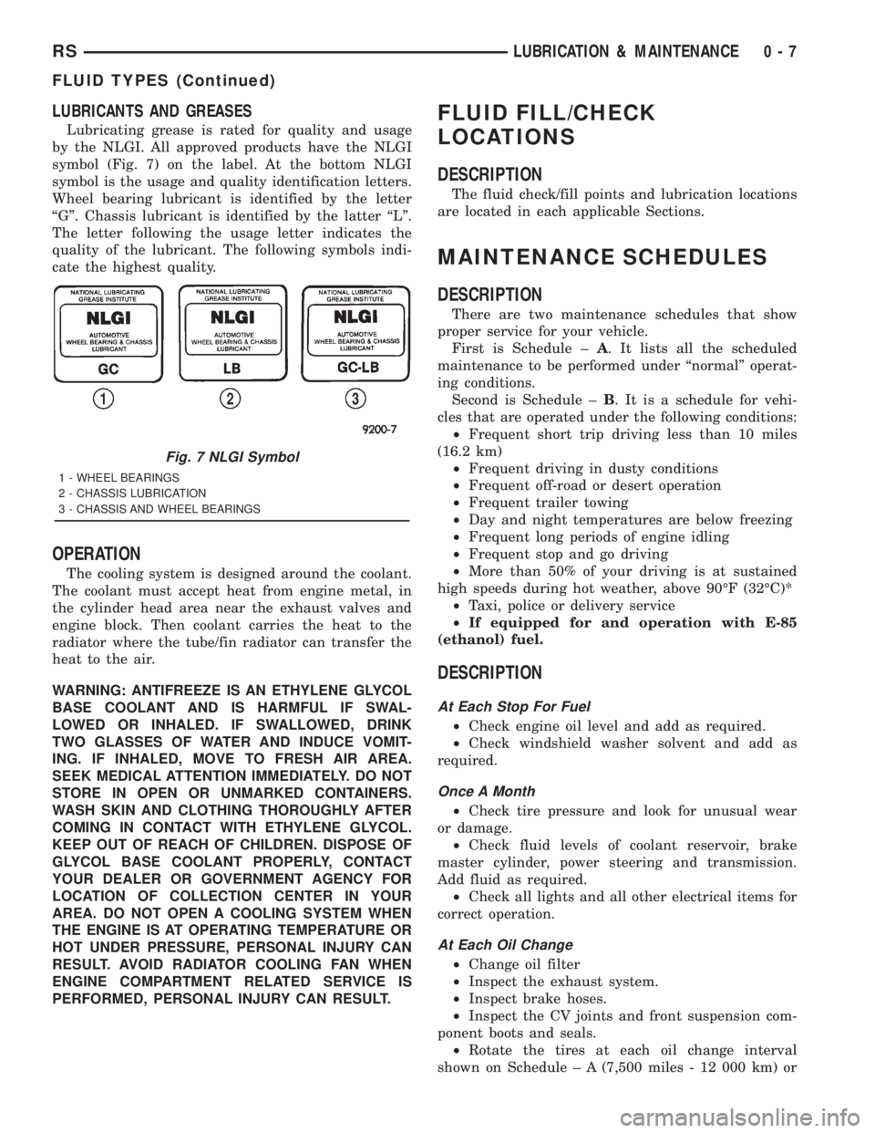
LUBRICANTS AND GREASES
Lubricating grease is rated for quality and usage
by the NLGI. All approved products have the NLGI
symbol (Fig. 7) on the label. At the bottom NLGI
symbol is the usage and quality identification letters.
Wheel bearing lubricant is identified by the letter
ªGº. Chassis lubricant is identified by the latter ªLº.
The letter following the usage letter indicates the
quality of the lubricant. The following symbols indi-
cate the highest quality.
OPERATION
The cooling system is designed around the coolant.
The coolant must accept heat from engine metal, in
the cylinder head area near the exhaust valves and
engine block. Then coolant carries the heat to the
radiator where the tube/fin radiator can transfer the
heat to the air.
WARNING: ANTIFREEZE IS AN ETHYLENE GLYCOL
BASE COOLANT AND IS HARMFUL IF SWAL-
LOWED OR INHALED. IF SWALLOWED, DRINK
TWO GLASSES OF WATER AND INDUCE VOMIT-
ING. IF INHALED, MOVE TO FRESH AIR AREA.
SEEK MEDICAL ATTENTION IMMEDIATELY. DO NOT
STORE IN OPEN OR UNMARKED CONTAINERS.
WASH SKIN AND CLOTHING THOROUGHLY AFTER
COMING IN CONTACT WITH ETHYLENE GLYCOL.
KEEP OUT OF REACH OF CHILDREN. DISPOSE OF
GLYCOL BASE COOLANT PROPERLY, CONTACT
YOUR DEALER OR GOVERNMENT AGENCY FOR
LOCATION OF COLLECTION CENTER IN YOUR
AREA. DO NOT OPEN A COOLING SYSTEM WHEN
THE ENGINE IS AT OPERATING TEMPERATURE OR
HOT UNDER PRESSURE, PERSONAL INJURY CAN
RESULT. AVOID RADIATOR COOLING FAN WHEN
ENGINE COMPARTMENT RELATED SERVICE IS
PERFORMED, PERSONAL INJURY CAN RESULT.
FLUID FILL/CHECK
LOCATIONS
DESCRIPTION
The fluid check/fill points and lubrication locations
are located in each applicable Sections.
MAINTENANCE SCHEDULES
DESCRIPTION
There are two maintenance schedules that show
proper service for your vehicle.
First is Schedule ±A. It lists all the scheduled
maintenance to be performed under ªnormalº operat-
ing conditions.
Second is Schedule ±B. It is a schedule for vehi-
cles that are operated under the following conditions:
²Frequent short trip driving less than 10 miles
(16.2 km)
²Frequent driving in dusty conditions
²Frequent off-road or desert operation
²Frequent trailer towing
²Day and night temperatures are below freezing
²Frequent long periods of engine idling
²Frequent stop and go driving
²More than 50% of your driving is at sustained
high speeds during hot weather, above 90ÉF (32ÉC)*
²Taxi, police or delivery service
²If equipped for and operation with E-85
(ethanol) fuel.
DESCRIPTION
At Each Stop For Fuel
²Check engine oil level and add as required.
²Check windshield washer solvent and add as
required.
Once A Month
²Check tire pressure and look for unusual wear
or damage.
²Check fluid levels of coolant reservoir, brake
master cylinder, power steering and transmission.
Add fluid as required.
²Check all lights and all other electrical items for
correct operation.
At Each Oil Change
²Change oil filter
²Inspect the exhaust system.
²Inspect brake hoses.
²Inspect the CV joints and front suspension com-
ponent boots and seals.
²Rotate the tires at each oil change interval
shown on Schedule ± A (7,500 miles - 12 000 km) or
Fig. 7 NLGI Symbol
1 - WHEEL BEARINGS
2 - CHASSIS LUBRICATION
3 - CHASSIS AND WHEEL BEARINGS
RSLUBRICATION & MAINTENANCE0-7
FLUID TYPES (Continued)
Page 1496 of 4284
every other interval on Schedule ± B (6,000 miles -
10 000 km).
²Check the engine coolant level, hoses, and
clamps.
EMISSION CONTROL SYSTEM MAINTENANCE
The scheduled emission maintenance listed inbold
typeon the Maintenance Schedules, must be done at
the mileage specified to assure the continued proper
functioning of the emission control system. These,
and all other maintenance services included in this
manual, should be done to provide the best vehicle
performance and reliability. More frequent mainte-
nance may be needed for vehicles in severe operating
conditions such as dusty areas and very short trip
driving.
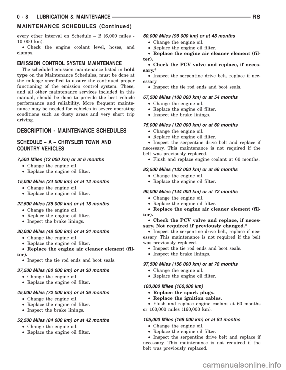
DESCRIPTION - MAINTENANCE SCHEDULES
SCHEDULE±A±CHRYSLER TOWN AND
COUNTRY VEHICLES
7,500 Miles (12 000 km) or at 6 months
²Change the engine oil.
²Replace the engine oil filter.
15,000 Miles (24 000 km) or at 12 months
²Change the engine oil.
²Replace the engine oil filter.
22,500 Miles (36 000 km) or at 18 months
²Change the engine oil.
²Replace the engine oil filter.
²Inspect the brake linings.
30,000 Miles (48 000 km) or at 24 months
²Change the engine oil.
²Replace the engine oil filter.
²Replace the engine air cleaner element (fil-
ter).
²Inspect the tie rod ends and boot seals.
37,500 Miles (60 000 km) or at 30 months
²Change the engine oil.
²Replace the engine oil filter.
45,000 Miles (72 000 km) or at 36 months
²Change the engine oil.
²Replace the engine oil filter.
²Inspect the brake linings.
52,500 Miles (84 000 km) or at 42 months
²Change the engine oil.
²Replace the engine oil filter.
60,000 Miles (96 000 km) or at 48 months
²Change the engine oil.
²Replace the engine oil filter.
²Replace the engine air cleaner element (fil-
ter).
²Check the PCV valve and replace, if neces-
sary.*
²Inspect the serpentine drive belt, replace if nec-
essary.
²Inspect the tie rod ends and boot seals.
67,500 Miles (108 000 km) or at 54 months
²Change the engine oil.
²Replace the engine oil filter.
²Inspect the brake linings.
75,000 Miles (120 000 km) or at 60 months
²Change the engine oil.
²Replace the engine oil filter.
²Inspect the serpentine drive belt and replace if
necessary. This maintenance is not required if the
belt was previously replaced.
²Flush and replace engine coolant at 60 months.
82,500 Miles (132 000 km) or at 66 months
²Change the engine oil.
²Replace the engine oil filter.
90,000 Miles (144 000 km) or at 72 months
²Change the engine oil.
²Replace the engine oil filter.
²Replace the engine air cleaner element (fil-
ter).
²Check the PCV valve and replace, if neces-
sary. Not required if previously changed.*
²Inspect the serpentine drive belt, replace if nec-
essary. This maintenance is not required if the belt
was previously replaced.
²Inspect the tie rod ends and boot seals.
²Inspect the brake linings.
97,500 Miles (156 000 km) or at 78 months
²Change the engine oil.
²Replace the engine oil filter.
100,000 Miles (160,000 km)
²Replace the spark plugs.
²Replace the ignition cables.
²Flush and replace engine coolant at 60 months
or 100,000 miles (160,000 km).
105,000 Miles (168 000 km) or at 84 months
²Change the engine oil.
²Replace the engine oil filter.
²Inspect the serpentine drive belt and replace if
necessary. This maintenance is not required if the
belt was previously replaced.
0 - 8 LUBRICATION & MAINTENANCERS
MAINTENANCE SCHEDULES (Continued)
Page 1497 of 4284
112,500 Miles (180 000 km) or at 90 months
²Change the engine oil.
²Replace the engine oil filter.
²Inspect the brake linings.
120,000 Miles (192 000 km) or at 96 months
²Change the engine oil.
²Replace the engine oil filter.
²Replace the engine air cleaner element (fil-
ter).
²Check and replace the PCV valve, if neces-
sary.*
²Inspect the serpentine drive belt. Not required if
replaced at 75,000, 90,000 or 105,000 miles.
²Inspect the tie rod ends and boot seals.
*This maintenance is recommended by Daimler-
Chrysler Corporation to the owner but is not
required to maintain the emissions warranty.
NOTE: Inspection and service should also be per-
formed anytime a malfunction is observed or sus-
pected. Retain all receipts.
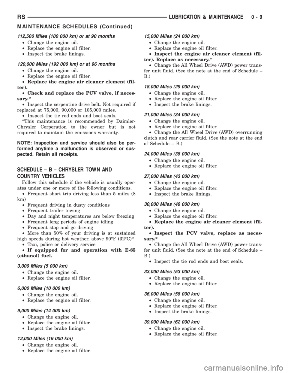
SCHEDULE±B±CHRYSLER TOWN AND
COUNTRY VEHICLES
Follow this schedule if the vehicle is usually oper-
ates under one or more of the following conditions.
²Frequent short trip driving less than 5 miles (8
km)
²Frequent driving in dusty conditions
²Frequent trailer towing
²Day and night temperatures are below freezing
²Frequent long periods of engine idling
²Frequent stop and go driving
²More than 50% of your driving is at sustained
high speeds during hot weather, above 90ÉF (32ÉC)*
²Taxi, police or delivery service
²If equipped for and operation with E-85
(ethanol) fuel.
3,000 Miles (5 000 km)
²Change the engine oil.
²Replace the engine oil filter.
6,000 Miles (10 000 km)
²Change the engine oil.
²Replace the engine oil filter.
9,000 Miles (14 000 km)
²Change the engine oil.
²Replace the engine oil filter.
²Inspect the brake linings.
12,000 Miles (19 000 km)
²Change the engine oil.
²Replace the engine oil filter.
15,000 Miles (24 000 km)
²Change the engine oil.
²Replace the engine oil filter.
²Inspect the engine air cleaner element (fil-
ter). Replace as necessary.*
²Change the All Wheel Drive (AWD) power trans-
fer unit fluid. (See the note at the end of Schedule ±
B.)
18,000 Miles (29 000 km)
²Change the engine oil.
²Replace the engine oil filter.
²Inspect the brake linings.
21,000 Miles (34 000 km)
²Change the engine oil.
²Replace the engine oil filter.
²Change the All Wheel Drive (AWD) overrunning
clutch and rear carrier fluid. (See the note at the end
of Schedule ± B.)
24,000 Miles (38 000 km)
²Change the engine oil.
²Replace the engine oil filter.
27,000 Miles (43 000 km)
²Change the engine oil.
²Replace the engine oil filter.
²Inspect the brake linings.
30,000 Miles (48 000 km)
²Change the engine oil.
²Replace the engine oil filter.
²Replace the engine air cleaner element (fil-
ter).
²Inspect the PCV valve, replace as neces-
sary.*
²Change the All Wheel Drive (AWD) power trans-
fer unit fluid. (See the note at the end of Schedule ±
B.)
²Inspect the tie rod ends and boot seals.
33,000 Miles (53 000 km)
²Change the engine oil.
²Replace the engine oil filter.
36,000 Miles (58 000 km)
²Change the engine oil.
²Replace the engine oil filter.
²Inspect the brake linings.
39,000 Miles (62 000 km)
²Change the engine oil.
²Replace the engine oil filter.
RSLUBRICATION & MAINTENANCE0-9
MAINTENANCE SCHEDULES (Continued)