2001 CHRYSLER VOYAGER glove box
[x] Cancel search: glove boxPage 24 of 4284

TABLE OF CONTENTS - Continued
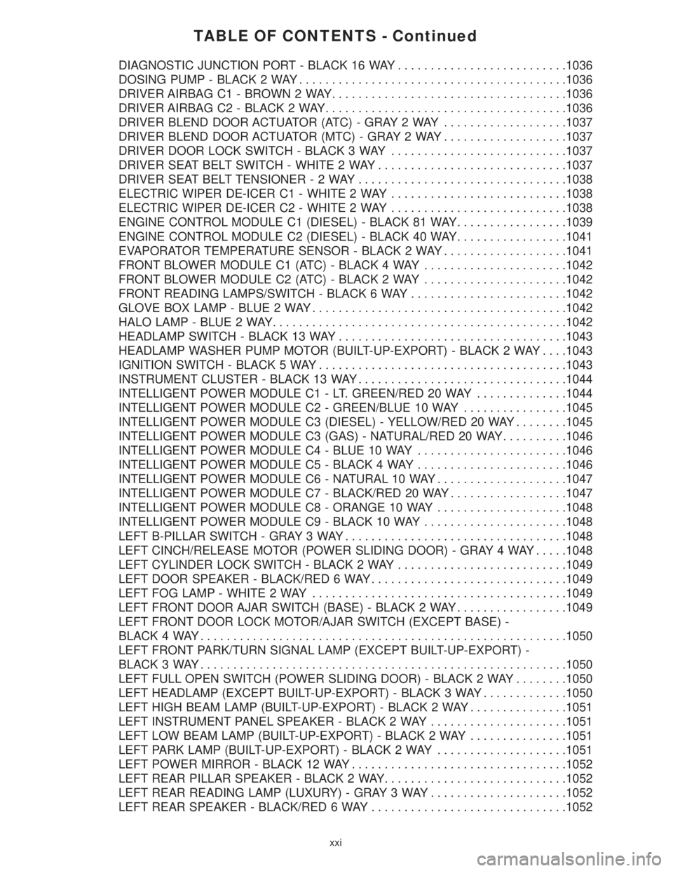
DIAGNOSTIC JUNCTION PORT - BLACK 16 WAY..........................1036
DOSING PUMP - BLACK 2 WAY.........................................1036
DRIVER AIRBAG C1 - BROWN 2 WAY....................................1036
DRIVER AIRBAG C2 - BLACK 2 WAY.....................................1036
DRIVER BLEND DOOR ACTUATOR (ATC) - GRAY 2 WAY...................1037
DRIVER BLEND DOOR ACTUATOR (MTC) - GRAY 2 WAY...................1037
DRIVER DOOR LOCK SWITCH - BLACK 3 WAY...........................1037
DRIVER SEAT BELT SWITCH - WHITE 2 WAY.............................1037
DRIVER SEAT BELT TENSIONER-2WAY................................1038
ELECTRIC WIPER DE-ICER C1 - WHITE 2 WAY...........................1038
ELECTRIC WIPER DE-ICER C2 - WHITE 2 WAY...........................1038
ENGINE CONTROL MODULE C1 (DIESEL) - BLACK 81 WAY.................1039
ENGINE CONTROL MODULE C2 (DIESEL) - BLACK 40 WAY.................1041
EVAPORATOR TEMPERATURE SENSOR - BLACK 2 WAY...................1041
FRONT BLOWER MODULE C1 (ATC) - BLACK 4 WAY......................1042
FRONT BLOWER MODULE C2 (ATC) - BLACK 2 WAY......................1042
FRONT READING LAMPS/SWITCH - BLACK 6 WAY........................1042
GLOVE BOX LAMP - BLUE 2 WAY.......................................1042
HALO LAMP - BLUE 2 WAY.............................................1042
HEADLAMP SWITCH - BLACK 13 WAY...................................1043
HEADLAMP WASHER PUMP MOTOR (BUILT-UP-EXPORT) - BLACK 2 WAY. . . .1043
IGNITION SWITCH - BLACK 5 WAY......................................1043
INSTRUMENT CLUSTER - BLACK 13 WAY................................1044
INTELLIGENT POWER MODULE C1 - LT. GREEN/RED 20 WAY..............1044
INTELLIGENT POWER MODULE C2 - GREEN/BLUE 10 WAY................1045
INTELLIGENT POWER MODULE C3 (DIESEL) - YELLOW/RED 20 WAY........1045
INTELLIGENT POWER MODULE C3 (GAS) - NATURAL/RED 20 WAY..........1046
INTELLIGENT POWER MODULE C4 - BLUE 10 WAY.......................1046
INTELLIGENT POWER MODULE C5 - BLACK 4 WAY.......................1046
INTELLIGENT POWER MODULE C6 - NATURAL 10 WAY....................1047
INTELLIGENT POWER MODULE C7 - BLACK/RED 20 WAY..................1047
INTELLIGENT POWER MODULE C8 - ORANGE 10 WAY....................1048
INTELLIGENT POWER MODULE C9 - BLACK 10 WAY......................1048
LEFT B-PILLAR SWITCH - GRAY 3 WAY..................................1048
LEFT CINCH/RELEASE MOTOR (POWER SLIDING DOOR) - GRAY 4 WAY.....1048
LEFT CYLINDER LOCK SWITCH - BLACK 2 WAY..........................1049
LEFT DOOR SPEAKER - BLACK/RED 6 WAY..............................1049
LEFT FOG LAMP - WHITE 2 WAY.......................................1049
LEFT FRONT DOOR AJAR SWITCH (BASE) - BLACK 2 WAY.................1049
LEFT FRONT DOOR LOCK MOTOR/AJAR SWITCH (EXCEPT BASE) -
BLACK 4 WAY........................................................1050
LEFT FRONT PARK/TURN SIGNAL LAMP (EXCEPT BUILT-UP-EXPORT) -
BLACK 3 WAY........................................................1050
LEFT FULL OPEN SWITCH (POWER SLIDING DOOR) - BLACK 2 WAY........1050
LEFT HEADLAMP (EXCEPT BUILT-UP-EXPORT) - BLACK 3 WAY.............1050
LEFT HIGH BEAM LAMP (BUILT-UP-EXPORT) - BLACK 2 WAY...............1051
LEFT INSTRUMENT PANEL SPEAKER - BLACK 2 WAY.....................1051
LEFT LOW BEAM LAMP (BUILT-UP-EXPORT) - BLACK 2 WAY...............1051
LEFT PARK LAMP (BUILT-UP-EXPORT) - BLACK 2 WAY....................1051
LEFT POWER MIRROR - BLACK 12 WAY.................................1052
LEFT REAR PILLAR SPEAKER - BLACK 2 WAY............................1052
LEFT REAR READING LAMP (LUXURY) - GRAY 3 WAY.....................1052
LEFT REAR SPEAKER - BLACK/RED 6 WAY..............................1052
xxi
Page 33 of 4284

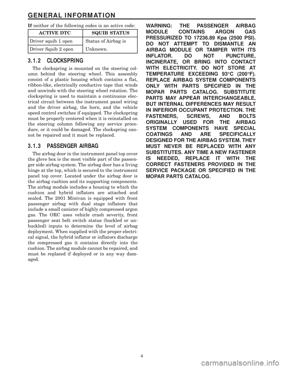
Ifneither of the following codes is an active code:
ACTIVE DTC SQUIB STATUS
Driver squib 1 open Status of Airbag is
Driver Squib 2 open Unknown.
3.1.2 CLOCKSPRING
The clockspring is mounted on the steering col-
umn behind the steering wheel. This assembly
consist of a plastic housing which contains a flat,
ribbon-like, electrically conductive tape that winds
and unwinds with the steering wheel rotation. The
clockspring is used to maintain a continuous elec-
trical circuit between the instrument panel wiring
and the driver airbag, the horn, and the vehicle
speed control switches if equipped. The clockspring
must be properly centered when it is reinstalled on
the steering column following any service proce-
dure, or it could be damaged. The clockspring can-
not be repaired and it must be replaced.
3.1.3 PASSENGER AIRBAG
The airbag door in the instrument panel top cover
the glove box is the most visible part of the passen-
ger side airbag system. The airbag door has a living
hinge at the top, which is secured to the instrument
panel top cover. Located under the airbag door is
the airbag cushion and its supporting components.
The airbag module includes a housing to which the
cushion and hybrid inflators are attached and
sealed. The 2001 Minivan is equipped with front
passenger airbag with dual stage inflators that
include a small canister of highly compressed argon
gas. The ORC uses vehicle crash severity, front
passenger seat belt switch status (buckled or un-
buckled) inputs to determine the level of airbag
deployment. When supplied with the proper electri-
cal signal, the hybrid inflator or inflators discharge
the compressed gas it contains directly into the
cushion. The airbag module cannot be repaired, and
must be replaced if deployed or in any way dam-
aged.
WARNING: THE PASSENGER AIRBAG
MODULE CONTAINS ARGON GAS
PRESSURIZED TO 17236.89 Kpa (2500 PSI).
DO NOT ATTEMPT TO DISMANTLE AN
AIRBAG MODULE OR TAMPER WITH ITS
INFLATOR. DO NOT PUNCTURE,
INCINERATE, OR BRING INTO CONTACT
WITH ELECTRICITY. DO NOT STORE AT
TEMPERATURE EXCEEDING 93ÉC (200ÉF).
REPLACE AIRBAG SYSTEM COMPONENTS
ONLY WITH PARTS SPECIFIED IN THE
MOPAR PARTS CATALOG. SUBSTITUTE
PARTS MAY APPEAR INTERCHANGEABLE,
BUT INTERNAL DIFFERENCES MAY RESULT
IN INFERIOR OCCUPANT PROTECTION. THE
FASTENERS, SCREWS, AND BOLTS
ORIGINALLY USED FOR THE AIRBAG
SYSTEM COMPONENTS HAVE SPECIAL
COATINGS AND ARE SPECIFICALLY
DESIGNED FOR THE AIRBAG SYSTEM. THEY
MUST NEVER BE REPLACED WITH ANY
SUBSTITUTES. ANY TIME A NEW FASTENER
IS NEEDED, REPLACE IT WITH THE
CORRECT FASTENERS PROVIDED IN THE
SERVICE PACKAGE OR SPECIFIED IN THE
MOPAR PARTS CATALOG.
4
GENERAL INFORMATION
Page 51 of 4284

On vehicles equipped with AutoStick, the display
includes an O/D OFF indicator that is illuminated
when the driver presses the Overdrive Off button
on the transaxle shifter.
3.11.1 INSTRUMENT CLUSTER SELF TEST
1. Depress and hold the Odometer Reset button.
2. Turn the ignition switch to the RUN/START
position.
3. Release the Odometer reset button.
The Instrument Cluster will illuminate all indi-
cators and step the gauges through several calibra-
tion points. Also, the odometer will display any
stored codes that may have set.
3.11.2 MESSAGE CENTER
The Message Center is located above the brow of
the Instrument Cluster. It houses the following
warning indicators: Check Engine/Service Engine
Soon, high beam, left and right turn signals, Secu-
rity Alarm Set, and low oil pressure. On base
models equipped with the three-speed transaxle,
these indicators appear in the face of the cluster.
The Security Alarm set indicator is a red circle.
Activation of Instrument Cluster indicators is
coordinated with indicators in the message center
and EVIC to avoid redundancy. A revised safety
standard now requires that the seat belt warning
lamp in the Instrument Cluster remain lit if the
driver seat belt is not buckled. A headlamp out ISO
indicator has been added to the Instrument Cluster
to alert the driver when a headlamp is not function-
ing.
3.12 INTERIOR LIGHTING
3.12.1 COURTESY LAMP CONTROL
The body controller has direct control over all of
the vehicle's courtesy lamps. The body computer
will illuminate the courtesy lamps under any of the
following conditions:
1. Any door ajar and courtesy lamp switch on the
headlamp switch is not in the dome off position.
2. The courtesy lamp switch on the headlamp
switch is in the dome on position.
3. A Remote Keyless Entry unlock message is re-
ceived.
4. Driver door unlocked with key (with VTSS only).
3.12.2 ILLUMINATED ENTRY
Illuminated entry will be initiated when the cus-
tomer enters the vehicle by unlocking the doors
with the key fob, or with the key if the vehicle is
equipped with vehicle theft alarm. Upon exiting thevehicle, if the lock button is pressed with a door
open, illuminated entry will cancel when the door
closes. If the doors are closed and the ignition
switch is turned on, the illuminated entry also
cancels. The illuminated entry feature will not
operate if the courtesy lamp switch is in the dome
off position.
3.12.3 INTERIOR LIGHTING BATTERY
SAVER
If any of the interior lamps are left on after the
ignition is turned off, the BCM will turn them off
after 8 minutes. To return to normal operation, the
courtesy lamps will operate after the dome lamp
switch or door ajar switch changes state. The glove
box and switched reading lamps require that the
ignition be turned to the on/acc position.
3.13 MEMORY SYSTEM
The memory system consists of power driver 's
seat, power mirrors and radio presets. The Memory
Seat/Mirror Module (MSMM) is located under the
driver 's seat. It receives input from the following:
driver 's manual 8-way seat switch, driver 's seat
position sensors, PCI bus circuits, and the power
mirror sensors. The module uses these inputs to
perform the following functions: position the driv-
er 's memory seat, both exterior mirrors (during
recalls), and send/receive the memory system infor-
mation over the PCI bus.
The Memory Set Switch is wired to the Body
Control Module (BCM). When a button (either #1 or
#2) is pressed on the set switch causes the to BCM
send a message to the MSMM which in turn sends
a motion status messages to the BCM. If the BCM
receives no motion from the MSMM it will send a
recall message to the MSMM and radio (once igni-
tion is in run or accessory). The MSMM will in turn
position the drivers seat, both mirrors along with
recalling the radio presets. If the drivers seat or
either exterior mirror is inoperative from its own
respective switches, use the service information
and schematic to diagnose the problem. This man-
ual addresses the memory problems only and it is
assumed there is not a basic component failure.
3.13.1 POWER SEAT
The memory power seat provides the driver with
2 position settings for the driver 's seat. Each power
seat motor is connected to the MSMM with two
motor drive circuits. Each circuit is switched be-
tween battery and ground. By being able to bi-
directionally drive the circuits, the MSMM controls
the movement of the motors based on input from
the power seat switch or from the position sensors
when performing a memory recall. Each motor
22
GENERAL INFORMATION
Page 567 of 4284

Symptom:
EVAPORATOR TEMPERATURE SENSOR CIRCUIT OPEN (ACTIVE)
- MANUAL A/C
When Monitored and Set Condition:
EVAPORATOR TEMPERATURE SENSOR CIRCUIT OPEN (ACTIVE) - MANUAL
A/C
When Monitored: With the ignition on.
Set Condition: This DTC will set if the Evaporator Temperature Sensor/sensor circuit is
open.
POSSIBLE CAUSES
EVAPORATOR TEMPERATURE SENSOR
EVAPORATOR TEMPERATURE SENSOR SIGNAL CIRCUIT OPEN
SENSOR GROUND CIRCUIT OPEN
A/C - HEATER CONTROL MODULE
TEST ACTION APPLICABILITY
1 Turn the ignition off.
Open the glove box door. Disconnect the glove box door roller latch from each side of
the glove box. Roll the glove box downward toward the floor.
Disconnect the in-line C202 harness connector.
Connect a jumper wire between the Evaporator Temperature Sensor Signal circuit
and the Sensor Ground circuit at the in-line C202 harness connector (HVAC side).
Turn the ignition on.
With the DRBIIItin Sensor Display, read the Evaporator Temperature Sensor
voltage.
Does the DRBIIItdisplay: 0.0 volts?All
Ye s®Check the wiring harness between the in-line C202 harness
connector (plenum side) and the Evap Temp Sensor for an open.
Repair as necessary. If Ok, replace the Evaporator Temperature
Sensor in accordance with the Service Information.
Perform BODY VERIFICATION TEST - VER 1.
No®Go To 2
538
HEATING & A/C
Page 568 of 4284

TEST ACTION APPLICABILITY
2 Turn the ignition off.
Disconnect the A/C - Heater Control Module C1 harness connector.
Open the glove box door. Disconnect the glove box door roller latch from each side of
the glove box. Roll the glove box downward toward the floor.
Disconnect the in-line C202 harness connector.
Measure the resistance of the Evaporator Temperature Sensor Signal circuit between
the A/C - Heater Control Module C1 harness connector and the in-line C202 harness
connector.
Is the resistance below 5.0 ohms?All
Ye s®Go To 3
No®Repair the Evaporator Temperature Sensor Signal circuit be-
tween the A/C - Heater Control Module C1 harness connector and
the in-line C202 harness connector (HVAC side) for an open.
Perform BODY VERIFICATION TEST - VER 1.
3 Turn the ignition off.
Disconnect the A/C - Heater Control Module C1 harness connector.
Open the glove box door. Disconnect the glove box door roller latch from each side of
the glove box. Roll the glove box downward toward the floor.
Disconnect the in-line C202 harness connector.
Measure the resistance of the Sensor Ground circuit between the A/C - Heater
Control Module C1 harness connector and the in-line C202 harness connector.
Is the resistance below 5.0 ohms?All
Ye s®Replace the A/C - Heater Control Module in accordance with the
Service Information.
Perform BODY VERIFICATION TEST - VER 1.
No®Repair the Sensor Ground circuit between the A/C - Heater
Control Module C1 harness connector and the in-line C202
harness connector (HVAC side) for an open.
Perform BODY VERIFICATION TEST - VER 1.
539
HEATING & A/C
EVAPORATOR TEMPERATURE SENSOR CIRCUIT OPEN (ACTIVE) -
MANUAL A/C Ð
Continued
Page 569 of 4284

Symptom:
EVAPORATOR TEMPERATURE SENSOR CIRCUIT SHORT (AC-
TIVE) - MANUAL A/C
When Monitored and Set Condition:
EVAPORATOR TEMPERATURE SENSOR CIRCUIT SHORT (ACTIVE) - MANUAL
A/C
When Monitored: With the ignition on.
Set Condition: This DTC will set if the Evaporator Temperature Sensor/sensor circuit is
shorted low.
POSSIBLE CAUSES
EVAPORATOR TEMPERATURE SENSOR
EVAPORATOR TEMPERATURE SENSOR SIGNAL CIRCUIT SHORT TO GROUND
EVAPORATOR TEMPERATURE SENSOR SIGNAL CIRCUIT SHORT TO SENSOR GROUND CIR-
CUIT
A/C - HEATER CONTROL MODULE
TEST ACTION APPLICABILITY
1 Turn the ignition off.
Open the glove box door. Disconnect the glove box door roller latch from each side of
the glove box. Roll the glove box downward toward the floor.
Disconnect the in-line C202 harness connector.
Turn the ignition on.
With the DRBIIItin Sensor Display, read the Evaporator Temperature Sensor
voltage.
Does the DRBIIItdisplay: 5.0 volts or greater?All
Ye s®Check the Evap Temp Sensor Signal circuit between the in-line
C202 harness connector (plenum side) and the Evap Temp Sensor
for a short to ground. Repair as necessary. If Ok, replace the
Evaporator Temperature Sensor in accordance with the Service
Info.
Perform BODY VERIFICATION TEST - VER 1.
No®Go To 2
540
HEATING & A/C
Page 570 of 4284

TEST ACTION APPLICABILITY
2 Turn the ignition off.
Disconnect the A/C - Heater Control Module C1 harness connector.
Open the glove box door. Disconnect the glove box door roller latch from each side of
the glove box. Roll the glove box downward toward the floor.
Disconnect the in-line C202 harness connector.
Measure the resistance between ground and the Evaporator Temperature Sensor
Signal circuit (HVAC side).
Is the resistance above 10K ohms?All
Ye s®Go To 3
No®Repair the Evaporator Temperature Sensor Signal circuit be-
tween the A/C - Heater Control Module C1 harness connector and
the in-line C202 harness connector (HVAC side) for a short to
ground.
Perform BODY VERIFICATION TEST - VER 1.
3 Turn the ignition off.
Disconnect the A/C - Heater Control Module C1 harness connector.
Open the glove box door. Disconnect the glove box door roller latch from each side of
the glove box. Roll the glove box downward toward the floor.
Disconnect the in-line C202 harness connector.
Measure the resistance between the Evaporator Temperature Sensor Signal circuit
and the Sensor Ground circuit (HVAC side).
Is the resistance above 10K ohms?All
Ye s®Replace the A/C - Heater Control Module in accordance with the
Service Information.
Perform BODY VERIFICATION TEST - VER 1.
No®Repair the Evaporator Temperature Sensor Signal circuit be-
tween the A/C - Heater Control Module C1 harness connector and
the in-line C202 harness connector (HVAC side) for a short to
Sensor Ground.
Perform BODY VERIFICATION TEST - VER 1.
541
HEATING & A/C
EVAPORATOR TEMPERATURE SENSOR CIRCUIT SHORT (ACTIVE) -
MANUAL A/C Ð
Continued
Page 1045 of 4284

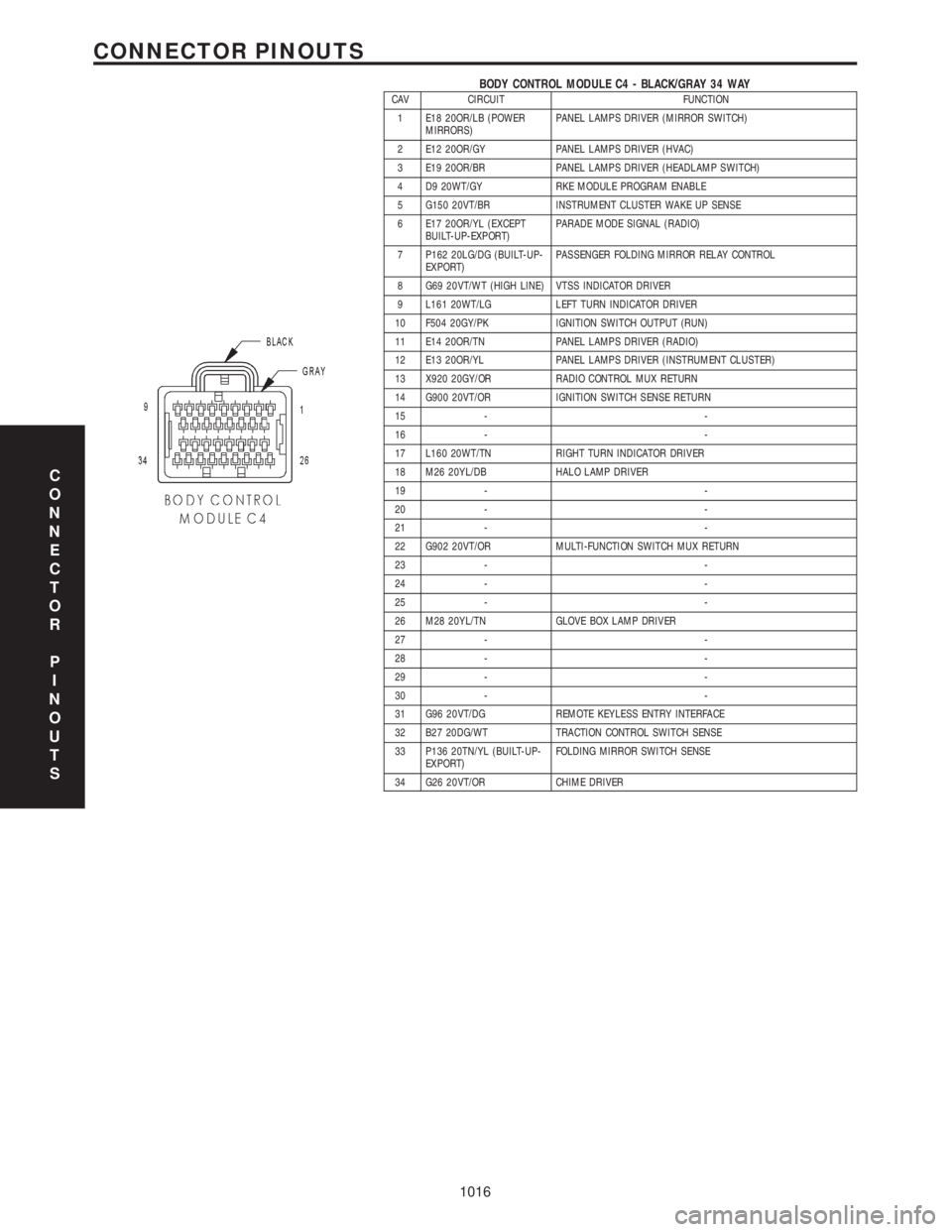
BODY CONTROL MODULE C4 - BLACK/GRAY 34 WAYCAV CIRCUIT FUNCTION
1 E18 20OR/LB (POWER
MIRRORS)PANEL LAMPS DRIVER (MIRROR SWITCH)
2 E12 20OR/GY PANEL LAMPS DRIVER (HVAC)
3 E19 20OR/BR PANEL LAMPS DRIVER (HEADLAMP SWITCH)
4 D9 20WT/GY RKE MODULE PROGRAM ENABLE
5 G150 20VT/BR INSTRUMENT CLUSTER WAKE UP SENSE
6 E17 20OR/YL (EXCEPT
BUILT-UP-EXPORT)PARADE MODE SIGNAL (RADIO)
7 P162 20LG/DG (BUILT-UP-
EXPORT)PASSENGER FOLDING MIRROR RELAY CONTROL
8 G69 20VT/WT (HIGH LINE) VTSS INDICATOR DRIVER
9 L161 20WT/LG LEFT TURN INDICATOR DRIVER
10 F504 20GY/PK IGNITION SWITCH OUTPUT (RUN)
11 E14 20OR/TN PANEL LAMPS DRIVER (RADIO)
12 E13 20OR/YL PANEL LAMPS DRIVER (INSTRUMENT CLUSTER)
13 X920 20GY/OR RADIO CONTROL MUX RETURN
14 G900 20VT/OR IGNITION SWITCH SENSE RETURN
15 - -
16 - -
17 L160 20WT/TN RIGHT TURN INDICATOR DRIVER
18 M26 20YL/DB HALO LAMP DRIVER
19 - -
20 - -
21 - -
22 G902 20VT/OR MULTI-FUNCTION SWITCH MUX RETURN
23 - -
24 - -
25 - -
26 M28 20YL/TN GLOVE BOX LAMP DRIVER
27 - -
28 - -
29 - -
30 - -
31 G96 20VT/DG REMOTE KEYLESS ENTRY INTERFACE
32 B27 20DG/WT TRACTION CONTROL SWITCH SENSE
33 P136 20TN/YL (BUILT-UP-
EXPORT)FOLDING MIRROR SWITCH SENSE
34 G26 20VT/OR CHIME DRIVER
C
O
N
N
E
C
T
O
R
P
I
N
O
U
T
S
1016
CONNECTOR PINOUTS