2001 CHRYSLER VOYAGER glove box
[x] Cancel search: glove boxPage 1071 of 4284
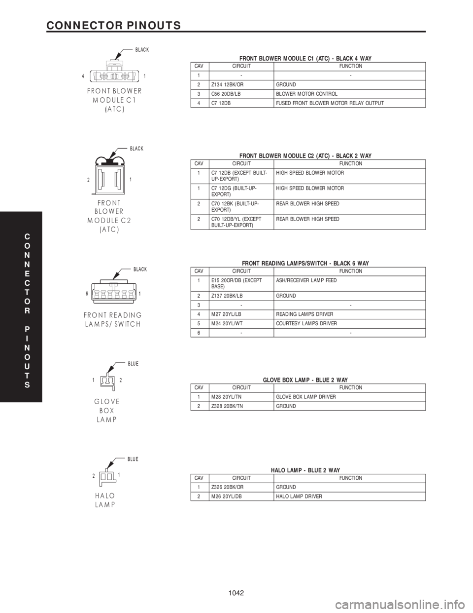
FRONT BLOWER MODULE C1 (ATC) - BLACK 4 WAYCAV CIRCUIT FUNCTION
1- -
2 Z134 12BK/OR GROUND
3 C56 20DB/LB BLOWER MOTOR CONTROL
4 C7 12DB FUSED FRONT BLOWER MOTOR RELAY OUTPUT
FRONT BLOWER MODULE C2 (ATC) - BLACK 2 WAYCAV CIRCUIT FUNCTION
1 C7 12DB (EXCEPT BUILT-
UP-EXPORT)HIGH SPEED BLOWER MOTOR
1 C7 12DG (BUILT-UP-
EXPORT)HIGH SPEED BLOWER MOTOR
2 C70 12BK (BUILT-UP-
EXPORT)REAR BLOWER HIGH SPEED
2 C70 12DB/YL (EXCEPT
BUILT-UP-EXPORT)REAR BLOWER HIGH SPEED
FRONT READING LAMPS/SWITCH - BLACK 6 WAYCAV CIRCUIT FUNCTION
1 E15 20OR/DB (EXCEPT
BASE)ASH/RECEIVER LAMP FEED
2 Z137 20BK/LB GROUND
3- -
4 M27 20YL/LB READING LAMPS DRIVER
5 M24 20YL/WT COURTESY LAMPS DRIVER
6- -
GLOVE BOX LAMP - BLUE 2 WAYCAV CIRCUIT FUNCTION
1 M28 20YL/TN GLOVE BOX LAMP DRIVER
2 Z328 20BK/TN GROUND
HALO LAMP - BLUE 2 WAYCAV CIRCUIT FUNCTION
1 Z326 20BK/OR GROUND
2 M26 20YL/DB HALO LAMP DRIVER
C
O
N
N
E
C
T
O
R
P
I
N
O
U
T
S
1042
CONNECTOR PINOUTS
Page 1808 of 4284
TEST 1
Test 1 determines of the antenna mast is insulated
from the base. Proceed as follows:
(1) Unplug the antenna coaxial cable from the
radio chassis and isolate. Remove the antenna mast.
(2) Connect an ohmmeter test lead to the inside
center of the antenna base. Connect the other test
lead to a metallic portion on the outside of the
antenna base. Check for continuity.
(3) There should be no continuity. If continuity is
found, replace the faulty or damaged antenna base
and cable assembly.
TEST 2
Test 2 checks the antenna for an open circuit as
follows:
(1) Unplug the antenna coaxial cable connector
from the radio chassis. Remove the antenna mast.
The painted mast prevents measurement directly
through the mast.
(2) Connect an ohmmeter test lead to the inside
center of the antenna base. Connect the other test
lead to the center pin of the antenna coaxial cable
connector.
(3) Continuity should exist (the ohmmeter should
only register a fraction of an ohm). High or infinite
resistance indicates damage to the base and cable
assembly. Replace the faulty base and cable if
required.
TEST 3
Test 3 checks the condition of the ground between
the antenna base and the vehicle body as follows:
(1) Connect one ohmmeter test lead to the fender
on an exposed metal area (paint and e-coat must be
penetrated to obtain continuity). Connect the other
test lead to the outer crimp on the antenna coaxial
cable connector.
(2) The resistance should be less than (1) ohm.
(3) If the resistance is more than (1) ohm, clean
and/or tighten the antenna base to the fender mount-
ing hardware.
REMOVAL
ANTENNA MAST AND CABLE LEAD
(1) Remove glove box from instrument panel,
(Refer to 23 - BODY/INSTRUMENT PANEL/GLOVE
BOX - REMOVAL).
(2) Disconnect antenna cable connector from exten-
sion cable (Fig. 2).
(3) Remove right kick trim panel.
(4) Disengage rubber grommet insulator from door
hinge pillar.
(5) Pull antenna cable through hinge pillar into
opening between door hinges.(6) Hoist and support vehicle on safety stands.
(7) Remove front wheel.
(8) Remove front wheelhouse splash shield. (Refer
to 23 - BODY/EXTERIOR/LF WHEELHOUSE
SPLASH SHIELD - REMOVAL).
(9) Remove antenna mast from antenna base (Fig.
3).
(10) Remove plastic cap from the cap nut. Using
cap nut tool, remove cap nut holding antenna base to
front fender (Fig. 4).
(11) Remove antenna base from under front fender.
ANTENNA EXTENSION CABLE
(1) Remove glove box. (Refer to 23 - BODY/IN-
STRUMENT PANEL/GLOVE BOX - REMOVAL).
(2) Disconnect extension cable end from antenna
cable end.
(3) Disconnect cable hanger clip from HVAC unit.
(4) Remove radio as necessary to gain access to
extension cable. (Refer to 8 - ELECTRICAL/AUDIO/
RADIO - REMOVAL).
(5) Disconnect extension cable from back of radio.
(6) Remove extension cable from vehicle.
INSTALLATION
ANTENNA MAST AND CABLE LEAD
(1) Install antenna base to underside of front
fender.
(2) Install cap nut holding antenna base to front
fender.
(3) Install plastic cap to the cap nut.
(4) Install antenna mast to antenna base.
(5) Install front wheelhouse splash shield.
(6) Install front wheel.
(7) Lower vehicle.
(8) Push antenna cable through opening in hinge
pillar.
(9) Insert rubber grommet into door hinge pillar.
(10) Install kick panel.
(11) Connect antenna cable connector to extension
cable.
(12) Install glove box to instrument panel.
ANTENNA EXTENSION CABLE
(1) Install extension cable to vehicle.
(2) Connect extension cable to back of radio.
(3) Install radio. (Refer to 8 - ELECTRICAL/AU-
DIO/RADIO - INSTALLATION).
(4) Connect cable hanger clip to HVAC unit.
(5) Connect extension cable end to antenna cable
end.
(6) Install glove box. (Refer to 23 - BODY/IN-
STRUMENT PANEL/GLOVE BOX - INSTALLA-
TION).
8A - 4 AUDIORS
ANTENNA BODY & CABLE (Continued)
Page 1814 of 4284
REMOTE SWITCHES
DESCRIPTION
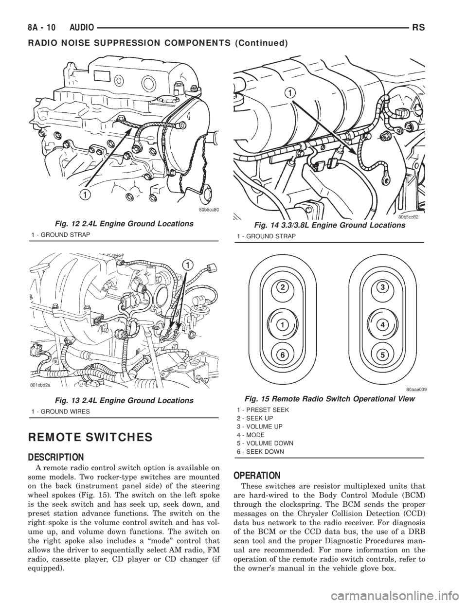
A remote radio control switch option is available on
some models. Two rocker-type switches are mounted
on the back (instrument panel side) of the steering
wheel spokes (Fig. 15). The switch on the left spoke
is the seek switch and has seek up, seek down, and
preset station advance functions. The switch on the
right spoke is the volume control switch and has vol-
ume up, and volume down functions. The switch on
the right spoke also includes a ªmodeº control that
allows the driver to sequentially select AM radio, FM
radio, cassette player, CD player or CD changer (if
equipped).
OPERATION
These switches are resistor multiplexed units that
are hard-wired to the Body Control Module (BCM)
through the clockspring. The BCM sends the proper
messages on the Chrysler Collision Detection (CCD)
data bus network to the radio receiver. For diagnosis
of the BCM or the CCD data bus, the use of a DRB
scan tool and the proper Diagnostic Procedures man-
ual are recommended. For more information on the
operation of the remote radio switch controls, refer to
the owner's manual in the vehicle glove box.
Fig. 12 2.4L Engine Ground Locations
1 - GROUND STRAP
Fig. 13 2.4L Engine Ground Locations
1 - GROUND WIRES
Fig. 14 3.3/3.8L Engine Ground Locations
1 - GROUND STRAP
Fig. 15 Remote Radio Switch Operational View
1 - PRESET SEEK
2 - SEEK UP
3 - VOLUME UP
4 - MODE
5 - VOLUME DOWN
6 - SEEK DOWN
8A - 10 AUDIORS
RADIO NOISE SUPPRESSION COMPONENTS (Continued)
Page 1856 of 4284
BATTERY SYSTEM
DESCRIPTION
A single 12-volt battery system is standard factory-
installed equipment on this model. All of the compo-
nents of the battery system are located within the
engine compartment of the vehicle. The service infor-
mation for the battery system in this vehicle covers
the following related components, which are covered
in further detail elsewhere in this service manual:
²Battery- The storage battery provides a reli-
able means of storing a renewable source of electrical
energy within the vehicle.
²Battery Cable- The battery cables connect the
battery terminal posts to the vehicle electrical sys-
tem.
²Battery Holddown- The battery holddown
hardware secures the battery in the battery tray in
the engine compartment.
²Battery Thermoguard- The battery thermo-
guard insulates the battery to protect it from engine
compartment temperature extremes.
²Battery Tray- The battery tray provides a
secure mounting location in the vehicle for the bat-
tery and an anchor point for the battery holddown
hardware.
For battery system maintenance schedules and
jump starting procedures, see the owner's manual in
the vehicle glove box. Optionally, refer to Lubrication
and Maintanance for the recommended battery main-
tenance schedules and for the proper battery jump
starting procedures. While battery charging can be
considered a maintenance procedure, the battery
charging procedures and related information are
located in the standard procedures section of this ser-
vice manual. This was done because the battery must
be fully-charged before any battery system diagnosis
or testing procedures can be performed. Refer to
Standard procedures for the proper battery charging
procedures.
OPERATION
The battery system is designed to provide a safe,
efficient, reliable and mobile means of delivering and
storing electrical energy. This electrical energy is
required to operate the engine starting system, as
well as to operate many of the other vehicle acces-sory systems for limited durations while the engine
and/or the charging system are not operating. The
battery system is also designed to provide a reserve
of electrical energy to supplement the charging sys-
tem for short durations while the engine is running
and the electrical current demands of the vehicle
exceed the output of the charging system. In addition
to delivering, and storing electrical energy for the
vehicle, the battery system serves as a capacitor and
voltage stabilizer for the vehicle electrical system. It
absorbs most abnormal or transient voltages caused
by the switching of any of the electrical components
or circuits in the vehicle.
DIAGNOSIS AND TESTING - BATTERY SYSTEM
The battery, starting, and charging systems in the
vehicle operate with one another and must be tested
as a single complete system. In order for the engine
to start and the battery to charge properly, all of the
components that are used in these systems must per-
form within specifications. It is important that the
battery, starting, and charging systems be thoroughly
tested and inspected any time a battery needs to be
charged or replaced. The cause of abnormal battery
discharge, overcharging or early battery failure must
be diagnosed and corrected before a battery is
replaced and before a vehicle is returned to service.
The service information for these systems has been
separated within this service manual to make it eas-
ier to locate the specific information you are seeking.
However, when attempting to diagnose any of these
systems, it is important that you keep their interde-
pendency in mind.
The diagnostic procedures used for the battery,
starting, and charging systems include the most
basic conventional diagnostic methods, to the more
sophisticated On-Board Diagnostics (OBD) built into
the Powertrain Control Module (PCM). Use of an
induction-type milliampere ammeter, a volt/ohmme-
ter, a battery charger, a carbon pile rheostat (load
tester) and a 12-volt test lamp may be required. All
OBD-sensed systems are monitored by the PCM.
Each monitored circuit is assigned a Diagnostic Trou-
ble Code (DTC). The PCM will store a DTC in elec-
tronic memory for any failure it detects. Refer to
Charging System for the proper charging system on-
board diagnostic test procedures.
8F - 2 BATTERY SYSTEMRS
Page 1904 of 4284
²Remote Keyless Entry Module (RKE)- Refer
toRemote Keyless Entry Modulein Power Locks
for more information.
²Electronic Vehicle Information Center
(EVIC)- Refer toElectronic Vehicle Information
Centerin Overhead Console for more information.
²Heated Seat Module (HSM)- Refer toHeated
Seat Modulein Electronic Control Modules for more
information.
²Memory Heated Seat Module (MHSM)-If
the vehicle is equipped with the Memory System,
refer toMemory Seat Mirror Module (MSMM)in
Electronic Control Modules for more information.
Refer toWiring Diagramsfor complete circuit
diagrams. Following are general descriptions of the
major components in the heated seat system.
OPERATION
The heated seat system will only operate when the
ignition switch is in the On position, and the surface
temperature at the front seat heating element sen-
sors is below the designed temperature set points of
the system. The heated seat system will not operate
in ambient temperatures greater than about 41É C
(105É F). The front seat heating elements and sensors
are hard wired to the Heated Seat Module (HSM) or
the Memory Heated Seat Module (MHSM).
The heated seat switches are hard wired to the
Body Control Module (BCM). The BCM monitors the
heated seat switch inputs, then sends heated seat
switch status messages to the HSM or MHSM over
the Programmable Communications Interface J1850
(PCI) data bus. The HSM or MHSM contains the con-
trol logic for the heated seat system. The HSM or
MHSM responds to the heated seat switch status
messages, ignition switch status messages, and the
front seat heating element sensor inputs by control-
ling the output to the front seat heating elements
through integral solid-state relays.
When a seat heater is turned on, the sensor
located on the seat cushion electric heater element
provides the HSM or MHSM with an input indicating
the surface temperature of the seat cushion. If the
surface temperature input is below the temperature
set point for the selected Low or High heated seat
switch position, the HSM or MHSM energizes the
integral solid-state relay, which supplies battery cur-
rent to the heating elements in the seat cushion and
back. When the sensor input indicates the correct
temperature set point has been achieved, the HSM or
MHSM de-energizes the solid-state relay. The HSM
or MHSM will continue to cycle the solid-state relay
as needed to maintain the temperature set point.
The HSM or MHSM and the seat heater elements
operate on non-switched battery current supplied
through the power seat fuse in the intelligent powermodule. However, the HSM or MHSM will automati-
cally turn off the heating elements if it detects an
open in the sensor circuit, a short in the heating ele-
ment circuit causing an excessive current draw, or
when the ignition switch is turned to the Off posi-
tion.
See the owner's manual in the vehicle glove box for
more information on the features, use and operation
of the heated seat system.
DRIVER HEATED SEAT
SWITCH
DESCRIPTION
The heated seat switches are mounted in the
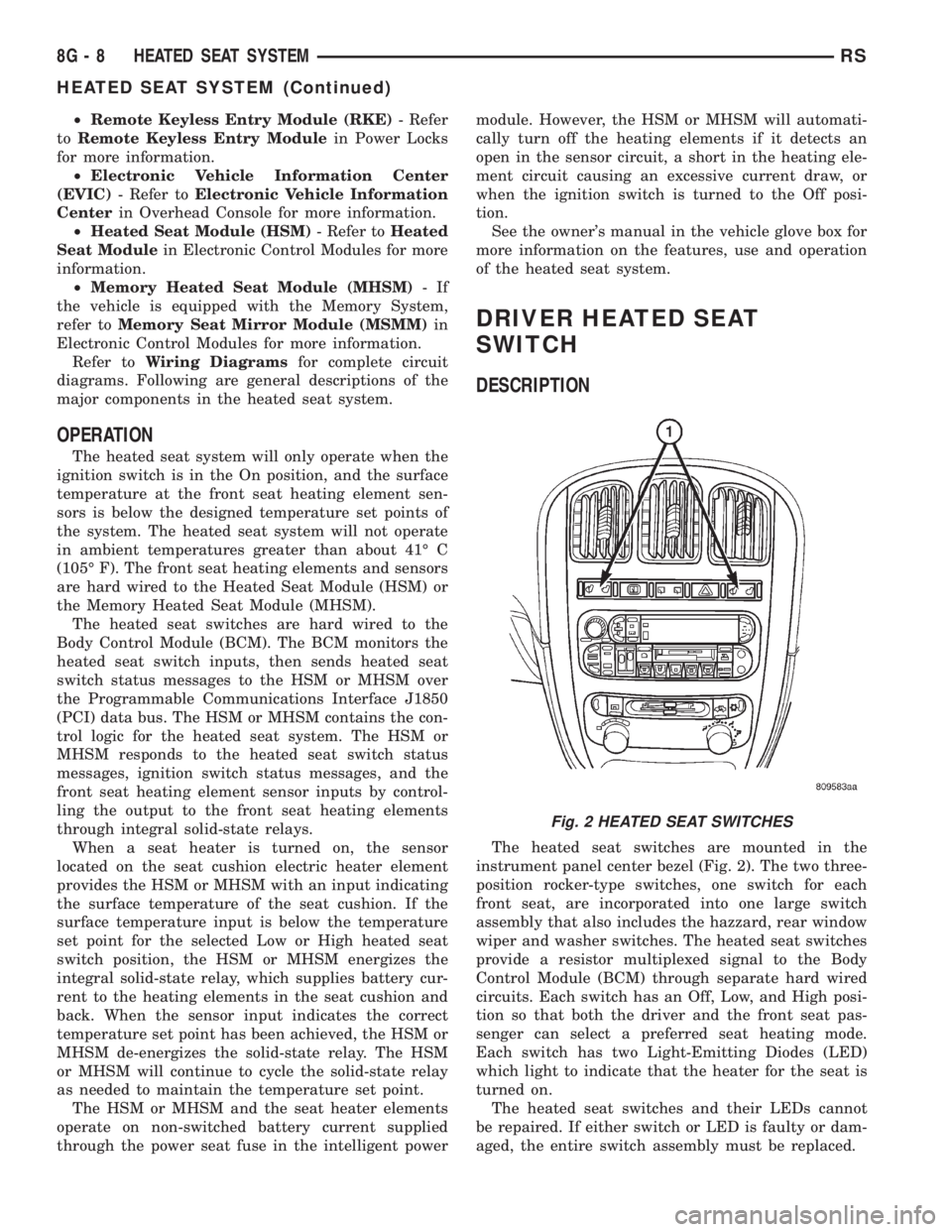
instrument panel center bezel (Fig. 2). The two three-
position rocker-type switches, one switch for each
front seat, are incorporated into one large switch
assembly that also includes the hazzard, rear window
wiper and washer switches. The heated seat switches
provide a resistor multiplexed signal to the Body
Control Module (BCM) through separate hard wired
circuits. Each switch has an Off, Low, and High posi-
tion so that both the driver and the front seat pas-
senger can select a preferred seat heating mode.
Each switch has two Light-Emitting Diodes (LED)
which light to indicate that the heater for the seat is
turned on.
The heated seat switches and their LEDs cannot
be repaired. If either switch or LED is faulty or dam-
aged, the entire switch assembly must be replaced.
Fig. 2 HEATED SEAT SWITCHES
8G - 8 HEATED SEAT SYSTEMRS
HEATED SEAT SYSTEM (Continued)
Page 1957 of 4284
LAMPS/LIGHTING - INTERIOR
TABLE OF CONTENTS
page page
LAMPS/LIGHTING - INTERIOR
SPECIFICATIONS........................17
CENTER CONSOLE LAMP SWITCH
REMOVAL..............................18
INSTALLATION...........................18
CLUSTER ILLUMINATION LAMPS
REMOVAL..............................18
INSTALLATION...........................18
COURTESY LAMP
REMOVAL..............................18
INSTALLATION...........................18
DOME LAMP
REMOVAL..............................18INSTALLATION...........................18
GLOVE BOX LAMP SWITCH
REMOVAL..............................18
INSTALLATION...........................19
LIFTGATE LAMP
REMOVAL..............................19
INSTALLATION...........................19
READING LAMP
REMOVAL..............................19
INSTALLATION...........................20
VANITY LAMP
REMOVAL..............................20
INSTALLATION...........................20
LAMPS/LIGHTING - INTERIOR
SPECIFICATIONS
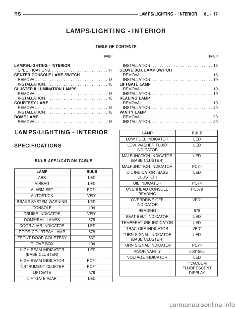
BULB APPLICATION TABLE
LAMP BULB
ABS LED
AIRBAG LED
ALARM SET PC74
AUTOSTICK VFD*
BRAKE SYSTEM WARNING LED
CONSOLE 194
CRUISE INDICATOR VFD*
DOME/RAIL LAMPS 578
DOOR AJAR INDICATOR LED
DOOR COURTESY LAMP 578
FRONT DOOR COURTESY 567
GLOVE BOX 194
HIGH BEAM INDICATOR
(BASE CLUSTER)LED
HIGH BEAM INDICATOR PC74
INSTRUMENT CLUSTER PC74
LIFTGATE 578
LIFTGATE AJAR LED
LAMP BULB
LOW FUEL INDICATOR LED
LOW WASHER FLUID
INDICATORLED
MALFUNCTION INDICATOR
(BASE CLUSTER)LED
MALFUNCTION INDICATOR PC74
OIL INDICATOR (BASE
CLUSTER)LED
OIL INDICATOR PC74
OVERHEAD CONSOLE
READINGPC579
OVERDRIVE OFF
INDICATORVFD*
READING 578
SEAT BELT INDICATOR LED
TEMPERATURE INDICATOR LED
TRAC OFF INDICATOR VFD*
TURN SIGNAL INDICATOR
(BASE CLUSTER)LED
TURN SIGNAL INDICATOR PC74
VISOR VANITY 6501966
VOLTAGE INDICATOR LED
* VACUUM
FLUORESCENT
DISPLAY
RSLAMPS/LIGHTING - INTERIOR8L-17
Page 1958 of 4284
CENTER CONSOLE LAMP
SWITCH
REMOVAL
(1) Disconnect and isolate the battery negative
cable.
(2) Open console lid and remove tray.
(3) Using a flat bladed tool, pry up on the switch.
(4) Remove bulb from switch.
INSTALLATION
(1) Install bulb into switch.
(2) Push switch into console opening.
(3) Install tray and close lid.
(4) Connect battery negative cable.
CLUSTER ILLUMINATION
LAMPS
REMOVAL
(1) Remove the Instrument Cluster. Refer to Elec-
trical, Instrument Cluster, Removal.
(2) Turn over cluster and expose the illumination
bulb sockets.
(3) Identify which bulb is defective and twist it out
of the cluster using a counterclockwise motion.
INSTALLATION
(1) Install the new bulb socket into the cluster
using a clockwise motion.
(2) Install the Instrument Cluster. Refer to Electri-
cal, Instrument Cluster, Installation.
COURTESY LAMP
REMOVAL
(1) Disconnect and isolate the battery negative
cable.
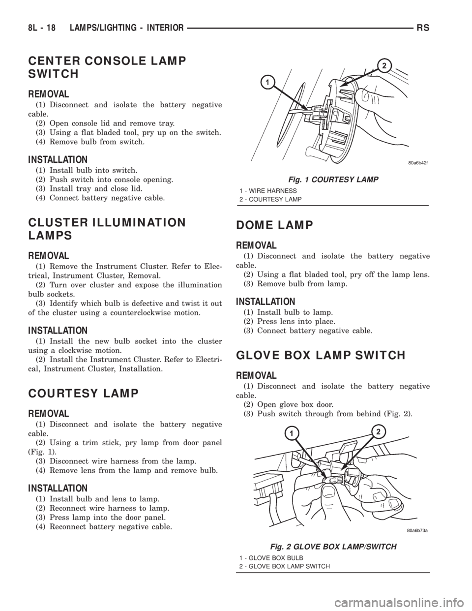
(2) Using a trim stick, pry lamp from door panel
(Fig. 1).
(3) Disconnect wire harness from the lamp.
(4) Remove lens from the lamp and remove bulb.
INSTALLATION
(1) Install bulb and lens to lamp.
(2) Reconnect wire harness to lamp.
(3) Press lamp into the door panel.
(4) Reconnect battery negative cable.
DOME LAMP
REMOVAL
(1) Disconnect and isolate the battery negative
cable.
(2) Using a flat bladed tool, pry off the lamp lens.
(3) Remove bulb from lamp.
INSTALLATION
(1) Install bulb to lamp.
(2) Press lens into place.
(3) Connect battery negative cable.
GLOVE BOX LAMP SWITCH
REMOVAL
(1) Disconnect and isolate the battery negative
cable.
(2) Open glove box door.
(3) Push switch through from behind (Fig. 2).
Fig. 1 COURTESY LAMP
1 - WIRE HARNESS
2 - COURTESY LAMP
Fig. 2 GLOVE BOX LAMP/SWITCH
1 - GLOVE BOX BULB
2 - GLOVE BOX LAMP SWITCH
8L - 18 LAMPS/LIGHTING - INTERIORRS
Page 1959 of 4284
(4) Disconnect wire harness from switch.
(5) Pull bulb from switch.
INSTALLATION
(1) Push bulb into switch.
(2) Connect wire harness to switch.
(3) Push switch into instrument panel.
(4) Close glove box door.
(5) Reconnect the battery negative cable.
LIFTGATE LAMP
REMOVAL
(1) Disconnect and isolate the battery negative
cable.
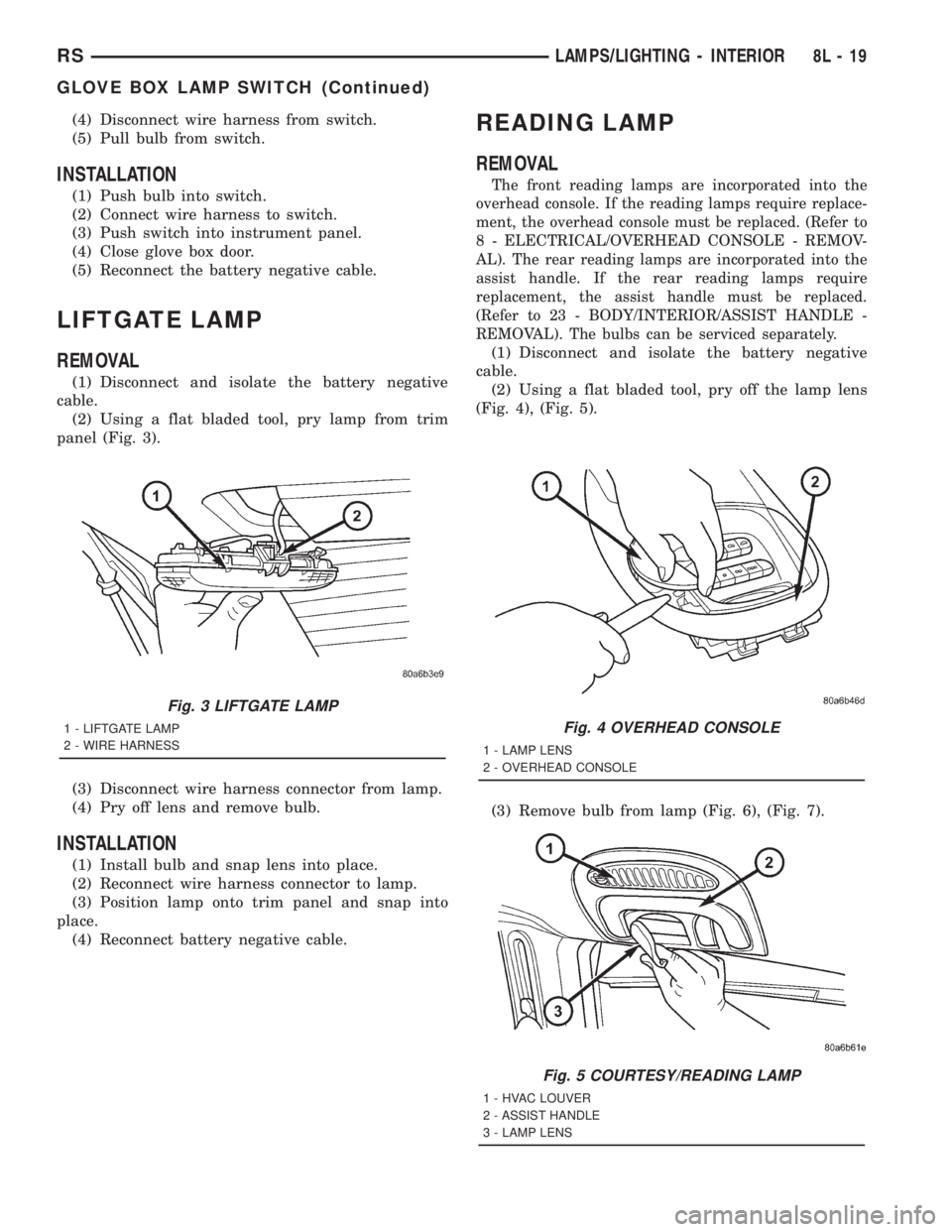
(2) Using a flat bladed tool, pry lamp from trim
panel (Fig. 3).
(3) Disconnect wire harness connector from lamp.
(4) Pry off lens and remove bulb.
INSTALLATION
(1) Install bulb and snap lens into place.
(2) Reconnect wire harness connector to lamp.
(3) Position lamp onto trim panel and snap into
place.
(4) Reconnect battery negative cable.
READING LAMP
REMOVAL
The front reading lamps are incorporated into the
overhead console. If the reading lamps require replace-
ment, the overhead console must be replaced. (Refer to
8 - ELECTRICAL/OVERHEAD CONSOLE - REMOV-
AL). The rear reading lamps are incorporated into the
assist handle. If the rear reading lamps require
replacement, the assist handle must be replaced.
(Refer to 23 - BODY/INTERIOR/ASSIST HANDLE -
REMOVAL). The bulbs can be serviced separately.
(1) Disconnect and isolate the battery negative
cable.
(2) Using a flat bladed tool, pry off the lamp lens
(Fig. 4), (Fig. 5).
(3) Remove bulb from lamp (Fig. 6), (Fig. 7).
Fig. 3 LIFTGATE LAMP
1 - LIFTGATE LAMP
2 - WIRE HARNESSFig. 4 OVERHEAD CONSOLE
1 - LAMP LENS
2 - OVERHEAD CONSOLE
Fig. 5 COURTESY/READING LAMP
1 - HVAC LOUVER
2 - ASSIST HANDLE
3 - LAMP LENS
RSLAMPS/LIGHTING - INTERIOR8L-19
GLOVE BOX LAMP SWITCH (Continued)