2001 CHRYSLER VOYAGER check transmission fluid
[x] Cancel search: check transmission fluidPage 1017 of 4284
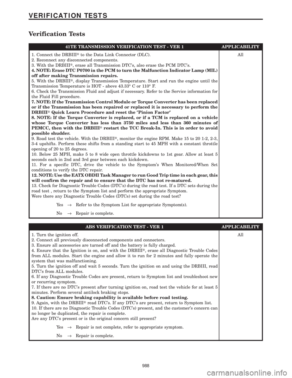
Verification Tests
41TE TRANSMISSION VERIFICATION TEST - VER 1 APPLICABILITY
1. Connect the DRBIIItto the Data Link Connector (DLC).
2. Reconnect any disconnected components.
3. With the DRBIIIt, erase all Transmission DTC's, also erase the PCM DTC's.
4. NOTE: Erase DTC P0700 in the PCM to turn the Malfunction Indicator Lamp (MIL)
off after making Transmission repairs.
5. With the DRBIIIt, display Transmission Temperature. Start and run the engine until the
Transmission Temperature is HOT - above 43.33É C or 110É F.
6. Check the Transmission Fluid and adjust if necessary. Refer to the Service information for
the Fluid Fill procedure.
7. NOTE: If the Transmission Control Module or Torque Converter has been replaced
or if the Transmission has been repaired or replaced it is necessary to perform the
DRBIIItQuick Learn Procedure and reset the(Pinion Factor(
8. NOTE: If the Torque Converter is replaced, or if a TCM is replaced on a vehicle
whose Torque Converter has less than 3750 miles and less than 360 minutes of
PEMCC, then with the DRBIIItrestart the TCC Break-In. This is in order to avoid
possible shudder.
9. Road test the vehicle. With the DRBIIIt, monitor the engine RPM. Make 15 to 20 1-2, 2-3,
3-4 upshifts. Perform these shifts from a standing start to 45 MPH with a constant throttle
opening of 20 to 25 degrees.
10. Below 25 MPH, make 5 to 8 wide open throttle kickdowns to 1st gear. Allow at least 5
seconds each in 2nd and 3rd gear between each kickdown.
11. For a specific DTC, drive the vehicle to the Symptom's When Monitored/When Set
conditions to verify the DTC repair.
12. NOTE: Use the EATX OBDII Task Manager to run Good Trip time in each gear, this
will confirm the repair and to ensure that the DTC has not re-matured.
13. Check for Diagnostic Trouble Codes (DTC's) during the road test. If a DTC sets during the
road test , return to the Symptom list and perform the appropriate Symptom.
Were there any Diagnostic Trouble Codes (DTCs) set during the road test?All
Ye s®Refer to the Symptom List for appropriate Symptom(s).
No®Repair is complete.
ABS VERIFICATION TEST - VER 1 APPLICABILITY
1. Turn the ignition off.
2. Connect all previously disconnected components and connectors.
3. Ensure all accessories are turned off and the battery is fully charged.
4. Ensure that the Ignition is on, and with the DRBIIIt, erase all Diagnostic Trouble Codes
from ALL modules. Start the engine and allow it to run for 2 minutes and fully operate the
system that was malfunctioning.
5. Turn the ignition off and wait 5 seconds. Turn the ignition on and using the DRBIII, read
DTC's from ALL modules.
6. If any Diagnostic Trouble Codes are present, return to Symptom list and troubleshoot new
or recurring symptom.
7. If there are no DTC's present after turning ignition on, road test the vehicle for at least 5
minutes. Perform several antilock braking stops.
8. Caution: Ensure braking capability is available before road testing.
9. Again, with the DRBIIItread DTC's. If any DTC's are present, return to Symptom list.
10. If there are no Diagnostic Trouble Codes (DTC's) present, and the customer's concern can
no longer be duplicated, the repair is complete.
Are any DTC's present or is the original concern still present?All
Ye s®Repair is not complete, refer to appropriate symptom.
No®Repair is complete.
988
VERIFICATION TESTS
Page 1492 of 4284
CONTAINER IDENTIFICATION
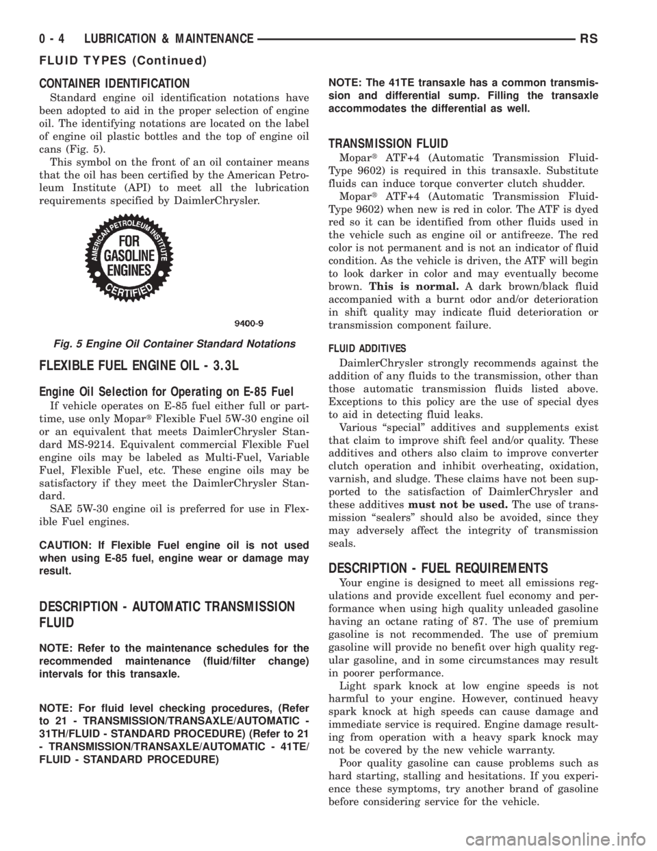
Standard engine oil identification notations have
been adopted to aid in the proper selection of engine
oil. The identifying notations are located on the label
of engine oil plastic bottles and the top of engine oil
cans (Fig. 5).
This symbol on the front of an oil container means
that the oil has been certified by the American Petro-
leum Institute (API) to meet all the lubrication
requirements specified by DaimlerChrysler.
FLEXIBLE FUEL ENGINE OIL - 3.3L
Engine Oil Selection for Operating on E-85 Fuel
If vehicle operates on E-85 fuel either full or part-
time, use only MopartFlexible Fuel 5W-30 engine oil
or an equivalent that meets DaimlerChrysler Stan-
dard MS-9214. Equivalent commercial Flexible Fuel
engine oils may be labeled as Multi-Fuel, Variable
Fuel, Flexible Fuel, etc. These engine oils may be
satisfactory if they meet the DaimlerChrysler Stan-
dard.
SAE 5W-30 engine oil is preferred for use in Flex-
ible Fuel engines.
CAUTION: If Flexible Fuel engine oil is not used
when using E-85 fuel, engine wear or damage may
result.
DESCRIPTION - AUTOMATIC TRANSMISSION
FLUID
NOTE: Refer to the maintenance schedules for the
recommended maintenance (fluid/filter change)
intervals for this transaxle.
NOTE: For fluid level checking procedures, (Refer
to 21 - TRANSMISSION/TRANSAXLE/AUTOMATIC -
31TH/FLUID - STANDARD PROCEDURE) (Refer to 21
- TRANSMISSION/TRANSAXLE/AUTOMATIC - 41TE/
FLUID - STANDARD PROCEDURE)NOTE: The 41TE transaxle has a common transmis-
sion and differential sump. Filling the transaxle
accommodates the differential as well.
TRANSMISSION FLUID
MopartATF+4 (Automatic Transmission Fluid-
Type 9602) is required in this transaxle. Substitute
fluids can induce torque converter clutch shudder.
MopartATF+4 (Automatic Transmission Fluid-
Type 9602) when new is red in color. The ATF is dyed
red so it can be identified from other fluids used in
the vehicle such as engine oil or antifreeze. The red
color is not permanent and is not an indicator of fluid
condition. As the vehicle is driven, the ATF will begin
to look darker in color and may eventually become
brown.This is normal.A dark brown/black fluid
accompanied with a burnt odor and/or deterioration
in shift quality may indicate fluid deterioration or
transmission component failure.
FLUID ADDITIVES
DaimlerChrysler strongly recommends against the
addition of any fluids to the transmission, other than
those automatic transmission fluids listed above.
Exceptions to this policy are the use of special dyes
to aid in detecting fluid leaks.
Various ªspecialº additives and supplements exist
that claim to improve shift feel and/or quality. These
additives and others also claim to improve converter
clutch operation and inhibit overheating, oxidation,
varnish, and sludge. These claims have not been sup-
ported to the satisfaction of DaimlerChrysler and
these additivesmust not be used.The use of trans-
mission ªsealersº should also be avoided, since they
may adversely affect the integrity of transmission
seals.
DESCRIPTION - FUEL REQUIREMENTS
Your engine is designed to meet all emissions reg-
ulations and provide excellent fuel economy and per-
formance when using high quality unleaded gasoline
having an octane rating of 87. The use of premium
gasoline is not recommended. The use of premium
gasoline will provide no benefit over high quality reg-
ular gasoline, and in some circumstances may result
in poorer performance.
Light spark knock at low engine speeds is not
harmful to your engine. However, continued heavy
spark knock at high speeds can cause damage and
immediate service is required. Engine damage result-
ing from operation with a heavy spark knock may
not be covered by the new vehicle warranty.
Poor quality gasoline can cause problems such as
hard starting, stalling and hesitations. If you experi-
ence these symptoms, try another brand of gasoline
before considering service for the vehicle.
Fig. 5 Engine Oil Container Standard Notations
0 - 4 LUBRICATION & MAINTENANCERS
FLUID TYPES (Continued)
Page 1495 of 4284
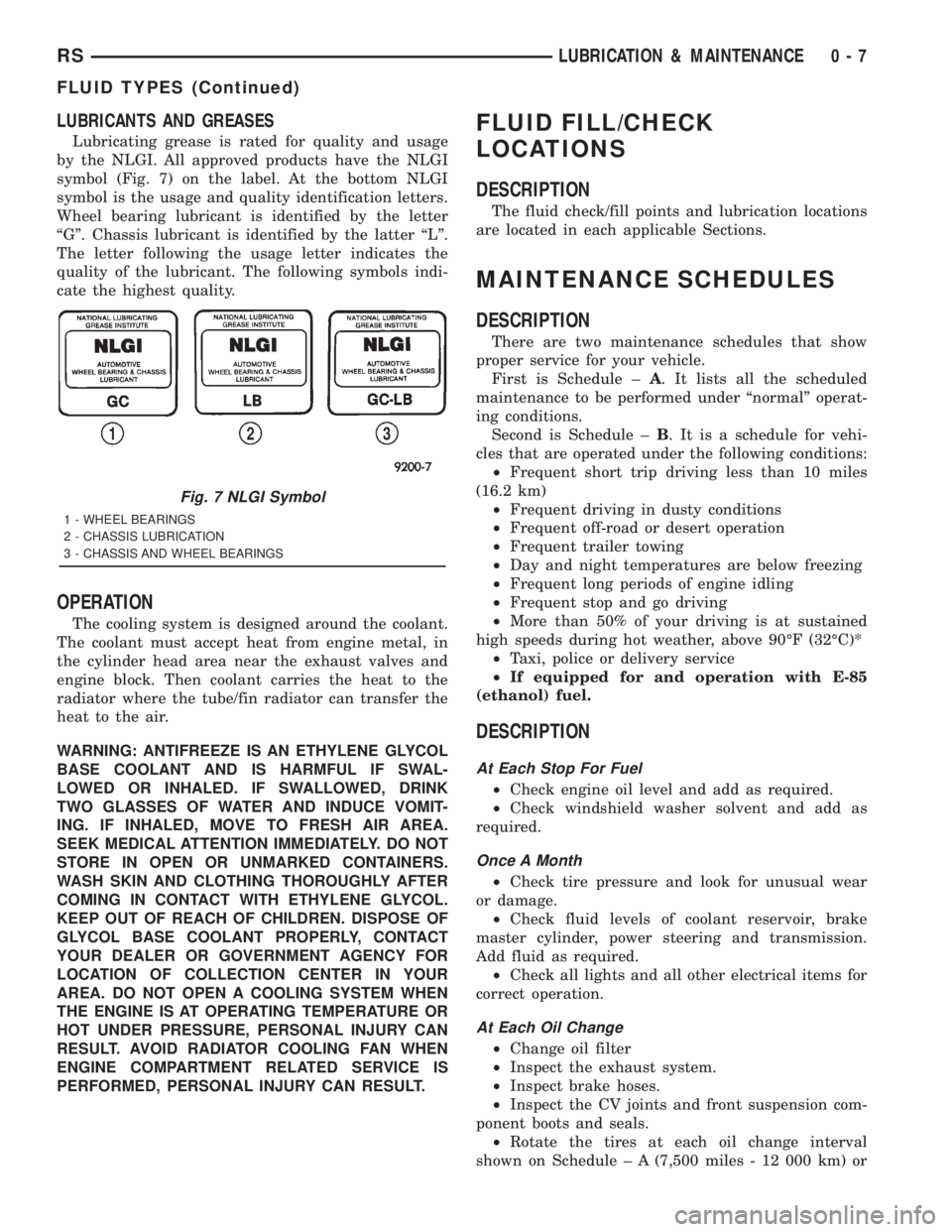
LUBRICANTS AND GREASES
Lubricating grease is rated for quality and usage
by the NLGI. All approved products have the NLGI
symbol (Fig. 7) on the label. At the bottom NLGI
symbol is the usage and quality identification letters.
Wheel bearing lubricant is identified by the letter
ªGº. Chassis lubricant is identified by the latter ªLº.
The letter following the usage letter indicates the
quality of the lubricant. The following symbols indi-
cate the highest quality.
OPERATION
The cooling system is designed around the coolant.
The coolant must accept heat from engine metal, in
the cylinder head area near the exhaust valves and
engine block. Then coolant carries the heat to the
radiator where the tube/fin radiator can transfer the
heat to the air.
WARNING: ANTIFREEZE IS AN ETHYLENE GLYCOL
BASE COOLANT AND IS HARMFUL IF SWAL-
LOWED OR INHALED. IF SWALLOWED, DRINK
TWO GLASSES OF WATER AND INDUCE VOMIT-
ING. IF INHALED, MOVE TO FRESH AIR AREA.
SEEK MEDICAL ATTENTION IMMEDIATELY. DO NOT
STORE IN OPEN OR UNMARKED CONTAINERS.
WASH SKIN AND CLOTHING THOROUGHLY AFTER
COMING IN CONTACT WITH ETHYLENE GLYCOL.
KEEP OUT OF REACH OF CHILDREN. DISPOSE OF
GLYCOL BASE COOLANT PROPERLY, CONTACT
YOUR DEALER OR GOVERNMENT AGENCY FOR
LOCATION OF COLLECTION CENTER IN YOUR
AREA. DO NOT OPEN A COOLING SYSTEM WHEN
THE ENGINE IS AT OPERATING TEMPERATURE OR
HOT UNDER PRESSURE, PERSONAL INJURY CAN
RESULT. AVOID RADIATOR COOLING FAN WHEN
ENGINE COMPARTMENT RELATED SERVICE IS
PERFORMED, PERSONAL INJURY CAN RESULT.
FLUID FILL/CHECK
LOCATIONS
DESCRIPTION
The fluid check/fill points and lubrication locations
are located in each applicable Sections.
MAINTENANCE SCHEDULES
DESCRIPTION
There are two maintenance schedules that show
proper service for your vehicle.
First is Schedule ±A. It lists all the scheduled
maintenance to be performed under ªnormalº operat-
ing conditions.
Second is Schedule ±B. It is a schedule for vehi-
cles that are operated under the following conditions:
²Frequent short trip driving less than 10 miles
(16.2 km)
²Frequent driving in dusty conditions
²Frequent off-road or desert operation
²Frequent trailer towing
²Day and night temperatures are below freezing
²Frequent long periods of engine idling
²Frequent stop and go driving
²More than 50% of your driving is at sustained
high speeds during hot weather, above 90ÉF (32ÉC)*
²Taxi, police or delivery service
²If equipped for and operation with E-85
(ethanol) fuel.
DESCRIPTION
At Each Stop For Fuel
²Check engine oil level and add as required.
²Check windshield washer solvent and add as
required.
Once A Month
²Check tire pressure and look for unusual wear
or damage.
²Check fluid levels of coolant reservoir, brake
master cylinder, power steering and transmission.
Add fluid as required.
²Check all lights and all other electrical items for
correct operation.
At Each Oil Change
²Change oil filter
²Inspect the exhaust system.
²Inspect brake hoses.
²Inspect the CV joints and front suspension com-
ponent boots and seals.
²Rotate the tires at each oil change interval
shown on Schedule ± A (7,500 miles - 12 000 km) or
Fig. 7 NLGI Symbol
1 - WHEEL BEARINGS
2 - CHASSIS LUBRICATION
3 - CHASSIS AND WHEEL BEARINGS
RSLUBRICATION & MAINTENANCE0-7
FLUID TYPES (Continued)
Page 1498 of 4284
42,000 Miles (67 000 km)
²Change the engine oil.
²Replace the engine oil filter.
²Change the All Wheel Drive (AWD) overrunning
clutch and rear carrier fluid. (See the note at the end
of Schedule ± B.)
45,000 Miles (72 000 km)
²Change the engine oil.
²Replace the engine oil filter.
²Inspect the engine air cleaner element (fil-
ter). Replace as necessary.*
²Change the All Wheel Drive (AWD) power trans-
fer unit fluid. (See the note at the end of Schedule ±
B.)
²Inspect the brake linings.
48,000 Miles (77 000 km)
²Change the engine oil.
²Replace the engine oil filter.
²Drain and refill the automatic transmission fluid
and replace the filter. (See the note at the end of
Schedule ± B.)
51,000 Miles (82 000 km)
²Change the engine oil.
54,000 Miles (86 000 km)
²Change the engine oil.
²Replace the engine oil filter.
²Inspect the brake linings.
57,000 Miles (91 000 km)
²Change the engine oil.
²Replace the engine oil filter.
60,000 Miles (96 000 km)
²Change the engine oil.
²Replace the engine oil filter.
²Replace the engine air cleaner element (fil-
ter).
²Inspect the PCV valve and replace if neces-
sary.*
²Inspect the serpentine drive belt and replace if
necessary.
²Change the All Wheel Drive (AWD) power trans-
fer unit fluid. (See the note at the end of Schedule ±
B.)
²Inspect the tie rod ends and boot seals.
63,000 Miles (101 000 km)
²Change the engine oil.
²Replace the engine oil filter.
²Inspect the brake linings.
²Change the All Wheel Drive (AWD) overrunning
clutch and rear carrier fluid. (See the note at the end
of Schedule ± B.)
66,000 Miles (106 000 km)
²Change the engine oil.
²Replace the engine oil filter.
69,000 Miles (110 000 km)
²Change the engine oil.
²Replace the engine oil filter.
72,000 Miles (115 000 km)
²Change the engine oil.
²Replace the engine oil filter.
²Inspect the brake linings.
75,000 Miles (120 000 km)
²Change the engine oil.
²Replace the engine oil filter.
²Inspect the engine air cleaner element (fil-
ter) and replace as necessary.*
²Replace the spark plugs.
²Replace the ignition cables.
²Inspect the serpentine drive belt and replace if
necessary. This maintenance is not required if belt
was previously replaced.
²Change the All Wheel Drive (AWD) power trans-
fer unit fluid. (See the note at the end of Schedule ±
B.)
78,000 Miles (125 000 km)
²Change the engine oil.
²Replace the engine oil filter.
81,000 Miles (130 000 km)
²Change the engine oil.
²Replace the engine oil filter.
²Inspect the brake linings.
84,000 Miles (134 000 km)
²Change the engine oil.
²Replace the engine oil filter.
²Change the All Wheel Drive (AWD) overrunning
clutch and rear carrier fluid. (See the note at the end
of Schedule ± B.)
87,000 Miles (139 000 km)
²Change the engine oil.
²Replace the engine oil filter.
90,000 Miles (144 000 km)
²Change the engine oil.
²Replace the engine oil filter.
²Replace the engine air cleaner element (fil-
ter).
²Check the PCV valve and replace if neces-
sary. Not required if previously changed.*
²Inspect the serpentine drive belt and replace if
necessary. This maintenance is not required if belt
was previously replaced.
0 - 10 LUBRICATION & MAINTENANCERS
MAINTENANCE SCHEDULES (Continued)
Page 1503 of 4284
²Check thePCV valveand replace if necessary.
Not required if previously changed.*
²Replace thespark plugson 2.4 liter engines.
²Inspect the generator belt on 2.4 liter engines
and replace if necessary.
²Inspect the serpentine drive belt (3.3 liter and
3.8 liter engines) and replace if necessary. This main-
tenance is not required if belt was previously
replaced.
²Change the All Wheel Drive (AWD) power trans-
fer unit fluid. (See the note at the end of Schedule ±
B.)
²Inspect the tie rod ends and boot seals.
²Inspect the brake linings.
93,000 Miles (149 000 km)
²Change the engine oil.
²Replace the engine oil filter.
96,000 Miles (154 000 km)
²Change the engine oil.
²Replace the engine oil filter.
²Drain and replace the automatic transmission
fluid and filter.
²Adjust bands on 3±speed transmission. (See the
note at the end of Schedule ± B.)
99,000 Miles (158 000 km)
²Change the engine oil.
²Replace the engine oil filter.
²Inspect the brake linings.
100,000 Miles (160 000 km)
²Flush and replace engine coolant at 60 months
or 100,000 miles (160 000 km).
102,000 Miles (163 000 km)
²Change the engine oil.
²Replace the engine oil filter.
105,000 Miles (168 000 km)
²Change the engine oil.
²Replace the engine oil filter.
²Inspect theengine air cleaner element (fil-
ter)and replace as necessary.*
²Inspect the generator belt on 2.4 liter engines
and replace if necessary.
²Inspect the serpentine drive belt on 3.3 liter and
3.8 liter engines and replace if necessary. This main-
tenance is not required if the belt was previously
replaced.
²Change the All Wheel Drive (AWD) power trans-
fer unit fluid. (See the note at the end of Schedule ±
B.)
²Change the All Wheel Drive (AWD) overrunning
clutch and rear carrier fluid. (See the note at the end
of Schedule ± B.)
108,000 Miles (173 000 km)
²Change the engine oil.
²Replace the engine oil filter.
²Inspect the brake linings.
111,000 Miles (178 000 km)
²Change the engine oil.
²Replace the engine oil filter.
114,000 Miles (182 000 km)
²Change the engine oil.
²Replace the engine oil filter.
117,000 Miles (187 000 km)
²Change the engine oil.
²Replace the engine oil filter.
²Inspect the brake linings.
120,000 Miles (192 000 km)
²Change the engine oil.
²Replace the engine oil filter.
²Replace theengine air cleaner element (fil-
ter).
²Inspect thePCV valveand replace as neces-
sary.*
²Replace thespark plugson 2.4 liter engines.
²Inspect the generator belt and power steering
pump belt tension, replace the belt if necessary on
2.4 liter engines.
²Inspect the serpentine drive belt on 3.3 liter and
3.8 liter engines. Not required if replaced at 75,000,
90,000 or 105,000 miles.
²Replace theengine timing belton 2.4 liter
engines.
²Change the All Wheel Drive (AWD) power trans-
fer unit fluid. (See the note at the end of Schedule ±
B.)
²Inspect the tie rod ends and boot seals.
* This maintenance is recommended by Daimler-
Chrysler Corporation to the owner but is not
required to maintain the emissions warranty.
NOTE: Operating the vehicle more than 50% in
heavy traffic during hot weather, above 90ÉF (32ÉC),
using vehicle for police, taxi, limousine type opera-
tion or trailer towing require the more frequent tran-
saxle service noted in Schedule ± B. Perform these
services if vehicle usually operate under these con-
ditions.
NOTE: The AWD power transfer unit fluid and the
AWD overrunning clutch/rear carrier fluid must be
changed at the more frequent intervals shown in
schedule B if the vehicle is operated under any of
the conditions noted by an asterisk at the begin-
ning of the schedule.
RSLUBRICATION & MAINTENANCE0-15
MAINTENANCE SCHEDULES (Continued)
Page 1509 of 4284
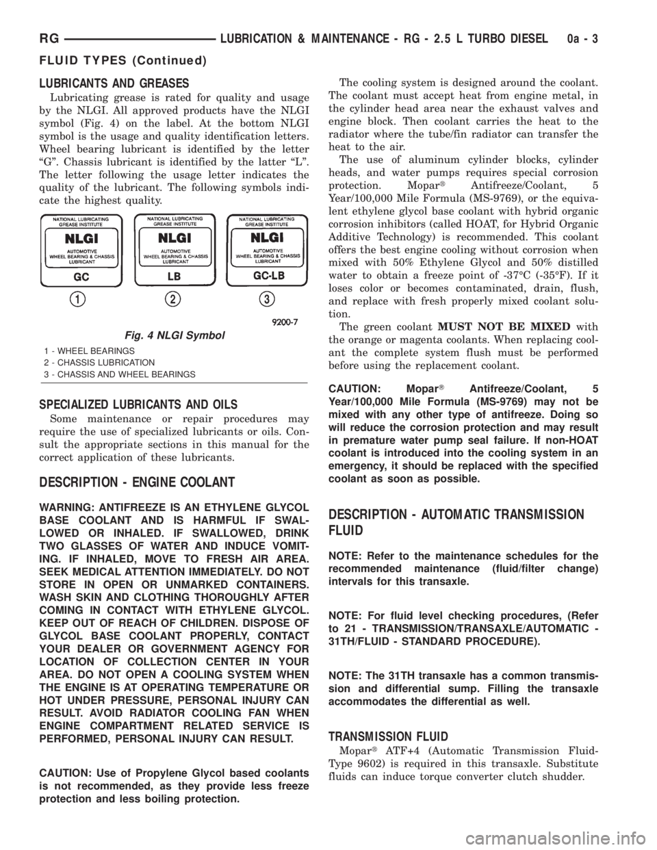
LUBRICANTS AND GREASES
Lubricating grease is rated for quality and usage
by the NLGI. All approved products have the NLGI
symbol (Fig. 4) on the label. At the bottom NLGI
symbol is the usage and quality identification letters.
Wheel bearing lubricant is identified by the letter
ªGº. Chassis lubricant is identified by the latter ªLº.
The letter following the usage letter indicates the
quality of the lubricant. The following symbols indi-
cate the highest quality.
SPECIALIZED LUBRICANTS AND OILS
Some maintenance or repair procedures may
require the use of specialized lubricants or oils. Con-
sult the appropriate sections in this manual for the
correct application of these lubricants.
DESCRIPTION - ENGINE COOLANT
WARNING: ANTIFREEZE IS AN ETHYLENE GLYCOL
BASE COOLANT AND IS HARMFUL IF SWAL-
LOWED OR INHALED. IF SWALLOWED, DRINK
TWO GLASSES OF WATER AND INDUCE VOMIT-
ING. IF INHALED, MOVE TO FRESH AIR AREA.
SEEK MEDICAL ATTENTION IMMEDIATELY. DO NOT
STORE IN OPEN OR UNMARKED CONTAINERS.
WASH SKIN AND CLOTHING THOROUGHLY AFTER
COMING IN CONTACT WITH ETHYLENE GLYCOL.
KEEP OUT OF REACH OF CHILDREN. DISPOSE OF
GLYCOL BASE COOLANT PROPERLY, CONTACT
YOUR DEALER OR GOVERNMENT AGENCY FOR
LOCATION OF COLLECTION CENTER IN YOUR
AREA. DO NOT OPEN A COOLING SYSTEM WHEN
THE ENGINE IS AT OPERATING TEMPERATURE OR
HOT UNDER PRESSURE, PERSONAL INJURY CAN
RESULT. AVOID RADIATOR COOLING FAN WHEN
ENGINE COMPARTMENT RELATED SERVICE IS
PERFORMED, PERSONAL INJURY CAN RESULT.
CAUTION: Use of Propylene Glycol based coolants
is not recommended, as they provide less freeze
protection and less boiling protection.The cooling system is designed around the coolant.
The coolant must accept heat from engine metal, in
the cylinder head area near the exhaust valves and
engine block. Then coolant carries the heat to the
radiator where the tube/fin radiator can transfer the
heat to the air.
The use of aluminum cylinder blocks, cylinder
heads, and water pumps requires special corrosion
protection. MopartAntifreeze/Coolant, 5
Year/100,000 Mile Formula (MS-9769), or the equiva-
lent ethylene glycol base coolant with hybrid organic
corrosion inhibitors (called HOAT, for Hybrid Organic
Additive Technology) is recommended. This coolant
offers the best engine cooling without corrosion when
mixed with 50% Ethylene Glycol and 50% distilled
water to obtain a freeze point of -37ÉC (-35ÉF). If it
loses color or becomes contaminated, drain, flush,
and replace with fresh properly mixed coolant solu-
tion.
The green coolantMUST NOT BE MIXEDwith
the orange or magenta coolants. When replacing cool-
ant the complete system flush must be performed
before using the replacement coolant.
CAUTION: MoparTAntifreeze/Coolant, 5
Year/100,000 Mile Formula (MS-9769) may not be
mixed with any other type of antifreeze. Doing so
will reduce the corrosion protection and may result
in premature water pump seal failure. If non-HOAT
coolant is introduced into the cooling system in an
emergency, it should be replaced with the specified
coolant as soon as possible.DESCRIPTION - AUTOMATIC TRANSMISSION
FLUID
NOTE: Refer to the maintenance schedules for the
recommended maintenance (fluid/filter change)
intervals for this transaxle.
NOTE: For fluid level checking procedures, (Refer
to 21 - TRANSMISSION/TRANSAXLE/AUTOMATIC -
31TH/FLUID - STANDARD PROCEDURE).
NOTE: The 31TH transaxle has a common transmis-
sion and differential sump. Filling the transaxle
accommodates the differential as well.
TRANSMISSION FLUID
MopartATF+4 (Automatic Transmission Fluid-
Type 9602) is required in this transaxle. Substitute
fluids can induce torque converter clutch shudder.
Fig. 4 NLGI Symbol
1 - WHEEL BEARINGS
2 - CHASSIS LUBRICATION
3 - CHASSIS AND WHEEL BEARINGS
RGLUBRICATION & MAINTENANCE - RG - 2.5 L TURBO DIESEL0a-3
FLUID TYPES (Continued)
Page 1582 of 4284
(7) Install steering knuckle in clevis bracket of
strut damper assembly. Install the strut damper to
steering knuckle attaching bolts. Tighten both bolts
to a torque of 81 N´m (60 ft. lbs.) plus an additional
1/4 turn.
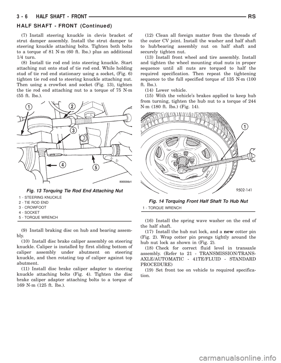
(8) Install tie rod end into steering knuckle. Start
attaching nut onto stud of tie rod end. While holding
stud of tie rod end stationary using a socket, (Fig. 6)
tighten tie rod end to steering knuckle attaching nut.
Then using a crowfoot and socket (Fig. 13), tighten
the tie rod end attaching nut to a torque of 75 N´m
(55 ft. lbs.).
(9) Install braking disc on hub and bearing assem-
bly.
(10) Install disc brake caliper assembly on steering
knuckle. Caliper is installed by first sliding bottom of
caliper assembly under abutment on steering
knuckle, and then rotating top of caliper against top
abutment.
(11) Install disc brake caliper adapter to steering
knuckle attaching bolts (Fig. 4). Tighten the disc
brake caliper adapter attaching bolts to a torque of
169 N´m (125 ft. lbs.).(12) Clean all foreign matter from the threads of
the outer CV joint. Install the washer and half shaft
to hub/bearing assembly nut on half shaft and
securely tighten nut.
(13) Install front wheel and tire assembly. Install
and tighten the wheel mounting stud nuts in proper
sequence until all nuts are torqued to half the
required specification. Then repeat the tightening
sequence to the full specified torque of 135 N´m (100
ft. lbs.).
(14) Lower vehicle.
(15) With the vehicle's brakes applied to keep hub
from turning, tighten the hub nut to a torque of 244
N´m (180 ft. lbs.) (Fig. 14).
(16) Install the spring wave washer on the end of
the half shaft.
(17) Install the hub nut lock, and anewcotter pin
(Fig. 2). Wrap cotter pin prongs tightly around the
hub nut lock as shown in (Fig. 2).
(18) Check for correct fluid level in transaxle
assembly. (Refer to 21 - TRANSMISSION/TRANS-
AXLE/AUTOMATIC - 41TE/FLUID - STANDARD
PROCEDURE)
(19) Set front toe on vehicle to required specifica-
tion.
Fig. 13 Torquing Tie Rod End Attaching Nut
1 - STEERING KNUCKLE
2 - TIE ROD END
3 - CROWFOOT
4 - SOCKET
5 - TORQUE WRENCHFig. 14 Torquing Front Half Shaft To Hub Nut
1 - TORQUE WRENCH
3 - 6 HALF SHAFT - FRONTRS
HALF SHAFT - FRONT (Continued)
Page 1603 of 4284
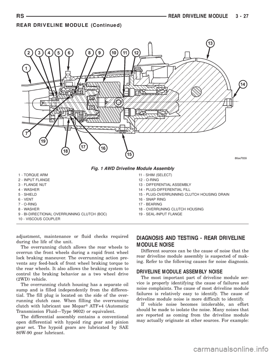
adjustment, maintenance or fluid checks required
during the life of the unit.
The overrunning clutch allows the rear wheels to
overrun the front wheels during a rapid front wheel
lock braking maneuver. The overrunning action pre-
vents any feed-back of front wheel braking torque to
the rear wheels. It also allows the braking system to
control the braking behavior as a two wheel drive
(2WD) vehicle.
The overrunning clutch housing has a separate oil
sump and is filled independently from the differen-
tial. The fill plug is located on the side of the over-
running clutch case. When filling the overrunning
clutch with lubricant use MopartATF+4 (Automatic
Transmission FluidÐType 9602) or equivalent.
The differential assembly contains a conventional
open differential with hypoid ring gear and pinion
gear set. The hypoid gears are lubricated by SAE
80W-90 gear lubricant.DIAGNOSIS AND TESTING - REAR DRIVELINE
MODULE NOISE
Different sources can be the cause of noise that the
rear driveline module assembly is suspected of mak-
ing. Refer to the following causes for noise diagnosis.
DRIVELINE MODULE ASSEMBLY NOISE
The most important part of driveline module ser-
vice is properly identifying the cause of failures and
noise complaints. The cause of most driveline module
failures is relatively easy to identify. The cause of
driveline module noise is more difficult to identify.
If vehicle noise becomes intolerable, an effort
should be made to isolate the noise. Many noises that
are reported as coming from the driveline module
may actually originate at other sources. For example:
Fig. 1 AWD Driveline Module Assembly
1 - TORQUE ARM
2 - INPUT FLANGE
3 - FLANGE NUT
4 - WASHER
5 - SHIELD
6 - VENT
7 - O-RING
8 - WASHER
9 - BI-DIRECTIONAL OVERRUNNING CLUTCH (BOC)
10 - VISCOUS COUPLER11 - SHIM (SELECT)
12 - O-RING
13 - DIFFERENTIAL ASSEMBLY
14 - PLUG-DIFFERENTIAL FILL
15 - PLUG-OVERRUNNING CLUTCH HOUSING DRAIN
16 - SNAP RING
17 - BEARING
18 - OVERRUNING CLUTCH HOUSING
19 - SEAL-INPUT FLANGE
RSREAR DRIVELINE MODULE3-27
REAR DRIVELINE MODULE (Continued)