2001 CHRYSLER VOYAGER check transmission fluid
[x] Cancel search: check transmission fluidPage 2942 of 4284
ing gear. This travel pushes and pulls the tie rods to
change the direction of the vehicle's front wheels.
Power assist steering provided by the power steer-
ing pump is controlled by an open center, rotary type
control valve which directs oil from the pump to
either side of the integral rack piston upon demand.
Road feel is controlled by the diameter of a torsion
bar which initially steers the vehicle. As required
steering effort increases, as in a turn, the torsion bar
twists, causing relative rotary motion between the
rotary valve body and the valve spool. This move-
ment directs oil behind the integral rack piston
which, in turn, builds up hydraulic pressure and
assists in the turning effort.
Manual steering control of the vehicle can be main-
tained if power steering assist is lost. However,
under this condition, steering effort is significantly
increased.
SERVICE WARNINGS AND CAUTIONS
WARNING: POWER STEERING FLUID, ENGINE
PARTS AND EXHAUST SYSTEM MAY BE
EXTREMELY HOT IF ENGINE HAS BEEN RUNNING.
DO NOT START ENGINE WITH ANY LOOSE OR DIS-
CONNECTED HOSES. DO NOT ALLOW HOSES TO
TOUCH HOT EXHAUST MANIFOLD OR CATALYST.
WARNING: FLUID LEVEL SHOULD BE CHECKED
WITH THE ENGINE OFF TO PREVENT PERSONAL
INJURY FROM MOVING PARTS.
CAUTION: When the system is open, cap all open
ends of the hoses, power steering pump fittings or
power steering gear ports to prevent entry of for-
eign material into the components.
REMOVAL - GEAR
CAUTION: Positioning the steering column in the
locked position will prevent the clockspring from
being accidentally over-extended when the steering
column is disconnected from the intermediate
steering coupler.
(1) Remove cap from power steering fluid reser-
voir.
(2) Using a siphon pump, remove as much fluid as
possible from the power steering fluid reservoir.
(3) With the ignition key in the locked position
turn the steering wheel to the left until the steering
wheel is in the locked position.
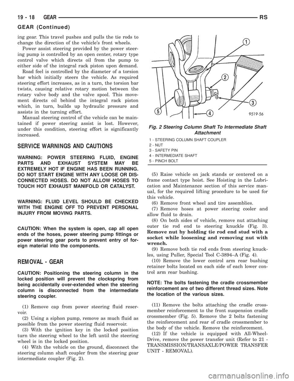
(4) With the vehicle on the ground, disconnect the
steering column shaft coupler from the steering gear
intermediate coupler (Fig. 2).(5) Raise vehicle on jack stands or centered on a
frame contact type hoist. See Hoisting in the Lubri-
cation and Maintenance section of this service man-
ual, for the required lifting procedure to be used for
this vehicle.
(6) Remove front wheel and tire assemblies.
(7) Remove hoses at power steering cooler and
allow fluid to drain.
(8) On both sides of vehicle, remove nut attaching
outer tie rod end to steering knuckle (Fig. 3).
Remove nut by holding tie rod end stud with a
socket while loosening and removing nut with
wrench.
(9) Remove both tie rod ends from steering knuck-
les, using Puller, Special Tool C-3894±A (Fig. 4).
(10) Remove the lower control arm rear bushing
retainer bolts located on each side of each lower con-
trol arm rear bushing.
NOTE: The bolts fastening the cradle crossmember
reinforcement are of two different thread sizes. Note
the location of the various sizes.
(11) Remove the bolts attaching the cradle cross-
member reinforcement to the front suspension cradle
crossmember (Fig. 5). Remove the 2 bolts fastening
the reinforcement and rear of cradle crossmember to
the body of the vehicle. Remove the reinforcement.
(12) If the vehicle is equipped with All-Wheel-
Drive, remove the power transfer unit (Refer to 21 -
TRANSMISSION/TRANSAXLE/POWER TRANSFER
UNIT - REMOVAL).
Fig. 2 Steering Column Shaft To Intermediate Shaft
Attachment
1 - STEERING COLUMN SHAFT COUPLER
2 - NUT
3 - SAFETY PIN
4 - INTERMEDIATE SHAFT
5 - PINCH BOLT
19 - 18 GEARRS
GEAR (Continued)
Page 2975 of 4284
END COVER SEAL
REMOVAL
The Power Transfer Unit must be removed from
the vehicle to perform this operation. (Refer to 21 -
TRANSMISSION/TRANSAXLE/POWER TRANSFER
UNIT - REMOVAL)
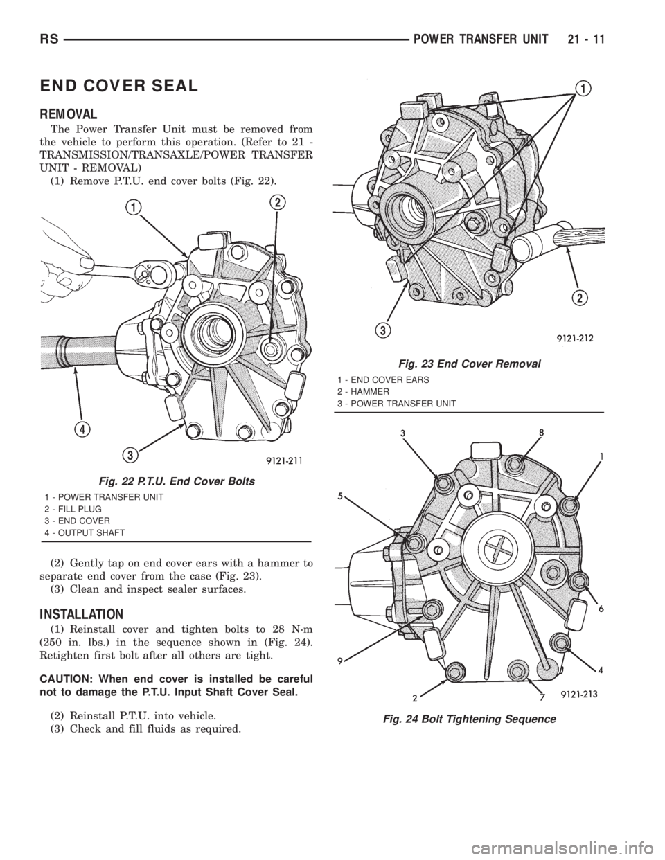
(1) Remove P.T.U. end cover bolts (Fig. 22).
(2) Gently tap on end cover ears with a hammer to
separate end cover from the case (Fig. 23).
(3) Clean and inspect sealer surfaces.
INSTALLATION
(1) Reinstall cover and tighten bolts to 28 N´m
(250 in. lbs.) in the sequence shown in (Fig. 24).
Retighten first bolt after all others are tight.
CAUTION: When end cover is installed be careful
not to damage the P.T.U. Input Shaft Cover Seal.
(2) Reinstall P.T.U. into vehicle.
(3) Check and fill fluids as required.
Fig. 22 P.T.U. End Cover Bolts
1 - POWER TRANSFER UNIT
2 - FILL PLUG
3 - END COVER
4 - OUTPUT SHAFT
Fig. 23 End Cover Removal
1 - END COVER EARS
2 - HAMMER
3 - POWER TRANSFER UNIT
Fig. 24 Bolt Tightening Sequence
RSPOWER TRANSFER UNIT21-11
Page 2985 of 4284
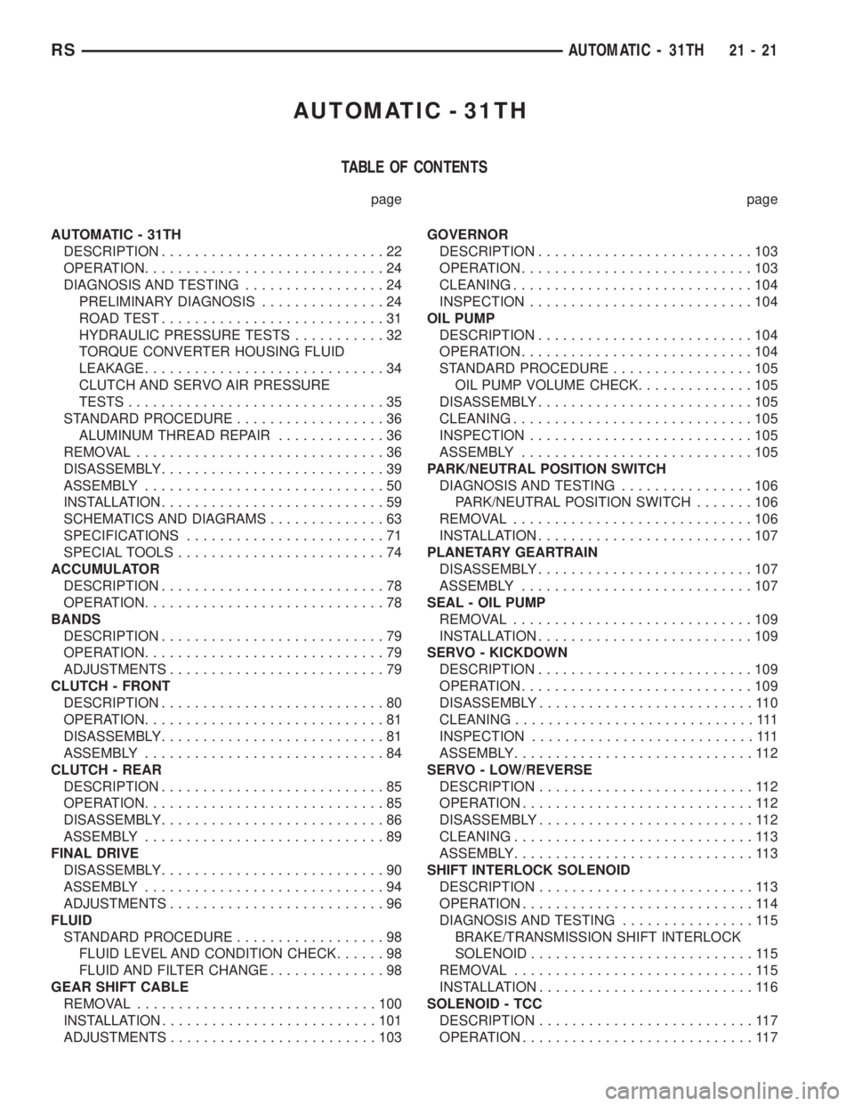
AUTOMATIC - 31TH
TABLE OF CONTENTS
page page
AUTOMATIC - 31TH
DESCRIPTION...........................22
OPERATION.............................24
DIAGNOSIS AND TESTING.................24
PRELIMINARY DIAGNOSIS...............24
ROAD TEST...........................31
HYDRAULIC PRESSURE TESTS...........32
TORQUE CONVERTER HOUSING FLUID
LEAKAGE.............................34
CLUTCH AND SERVO AIR PRESSURE
TESTS...............................35
STANDARD PROCEDURE..................36
ALUMINUM THREAD REPAIR.............36
REMOVAL..............................36
DISASSEMBLY...........................39
ASSEMBLY.............................50
INSTALLATION...........................59
SCHEMATICS AND DIAGRAMS..............63
SPECIFICATIONS........................71
SPECIAL TOOLS.........................74
ACCUMULATOR
DESCRIPTION...........................78
OPERATION.............................78
BANDS
DESCRIPTION...........................79
OPERATION.............................79
ADJUSTMENTS..........................79
CLUTCH - FRONT
DESCRIPTION...........................80
OPERATION.............................81
DISASSEMBLY...........................81
ASSEMBLY.............................84
CLUTCH - REAR
DESCRIPTION...........................85
OPERATION.............................85
DISASSEMBLY...........................86
ASSEMBLY.............................89
FINAL DRIVE
DISASSEMBLY...........................90
ASSEMBLY.............................94
ADJUSTMENTS..........................96
FLUID
STANDARD PROCEDURE..................98
FLUID LEVEL AND CONDITION CHECK......98
FLUID AND FILTER CHANGE..............98
GEAR SHIFT CABLE
REMOVAL.............................100
INSTALLATION..........................101
ADJUSTMENTS.........................103GOVERNOR
DESCRIPTION..........................103
OPERATION............................103
CLEANING.............................104
INSPECTION...........................104
OIL PUMP
DESCRIPTION..........................104
OPERATION............................104
STANDARD PROCEDURE.................105
OIL PUMP VOLUME CHECK..............105
DISASSEMBLY..........................105
CLEANING.............................105
INSPECTION...........................105
ASSEMBLY............................105
PARK/NEUTRAL POSITION SWITCH
DIAGNOSIS AND TESTING................106
PARK/NEUTRAL POSITION SWITCH.......106
REMOVAL.............................106
INSTALLATION..........................107
PLANETARY GEARTRAIN
DISASSEMBLY..........................107
ASSEMBLY............................107
SEAL - OIL PUMP
REMOVAL.............................109
INSTALLATION..........................109
SERVO - KICKDOWN
DESCRIPTION..........................109
OPERATION............................109
DISASSEMBLY..........................110
CLEANING.............................111
INSPECTION...........................111
ASSEMBLY.............................112
SERVO - LOW/REVERSE
DESCRIPTION..........................112
OPERATION............................112
DISASSEMBLY..........................112
CLEANING.............................113
ASSEMBLY.............................113
SHIFT INTERLOCK SOLENOID
DESCRIPTION..........................113
OPERATION............................114
DIAGNOSIS AND TESTING................115
BRAKE/TRANSMISSION SHIFT INTERLOCK
SOLENOID...........................115
REMOVAL.............................115
INSTALLATION..........................116
SOLENOID - TCC
DESCRIPTION..........................117
OPERATION............................117
RSAUTOMATIC - 31TH21-21
Page 2988 of 4284
OPERATION
Transmission output is directed to an integral dif-
ferential by a transfer gear system in the following
input-to-output ratios:
FIRST 2.69:1
SECOND 1.55:1
THIRD 1.00:1
REVERSE 2.10:1
DIAGNOSIS AND TESTING - PRELIMINARY
DIAGNOSIS
Automatic transaxle malfunctions are usually
caused by the following general conditions:
²Improper fluid level/condition
²Poor engine performance
²Improper engine or transaxle adjustments
²Transaxle hydraulic malfunctions²Transaxle mechanical malfunctions
Diagnosis of transaxle problems should always
begin with checking the easily accessible variables:
²Fluid level and condition
²Gearshift cable adjustment
²Throttle valve cable adjustment
After verifying or adjusting these variables, road
test the vehicle to determine if the problem has been
corrected or that further diagnosis is necessary. If the
problem still exists, refer to the following diagnosis
charts to aid in determining the source or cause of
failure.
Hydraulic pressure tests should be performed
when a transaxle internal failure is suspected. The
hydraulic flow charts, in the Schematics and Dia-
grams section of this group, outline fluid flow and
hydraulic circuitry. Circuit operation is provided for
all gear ranges. Normal working pressures are also
supplied for each of the gear ranges.
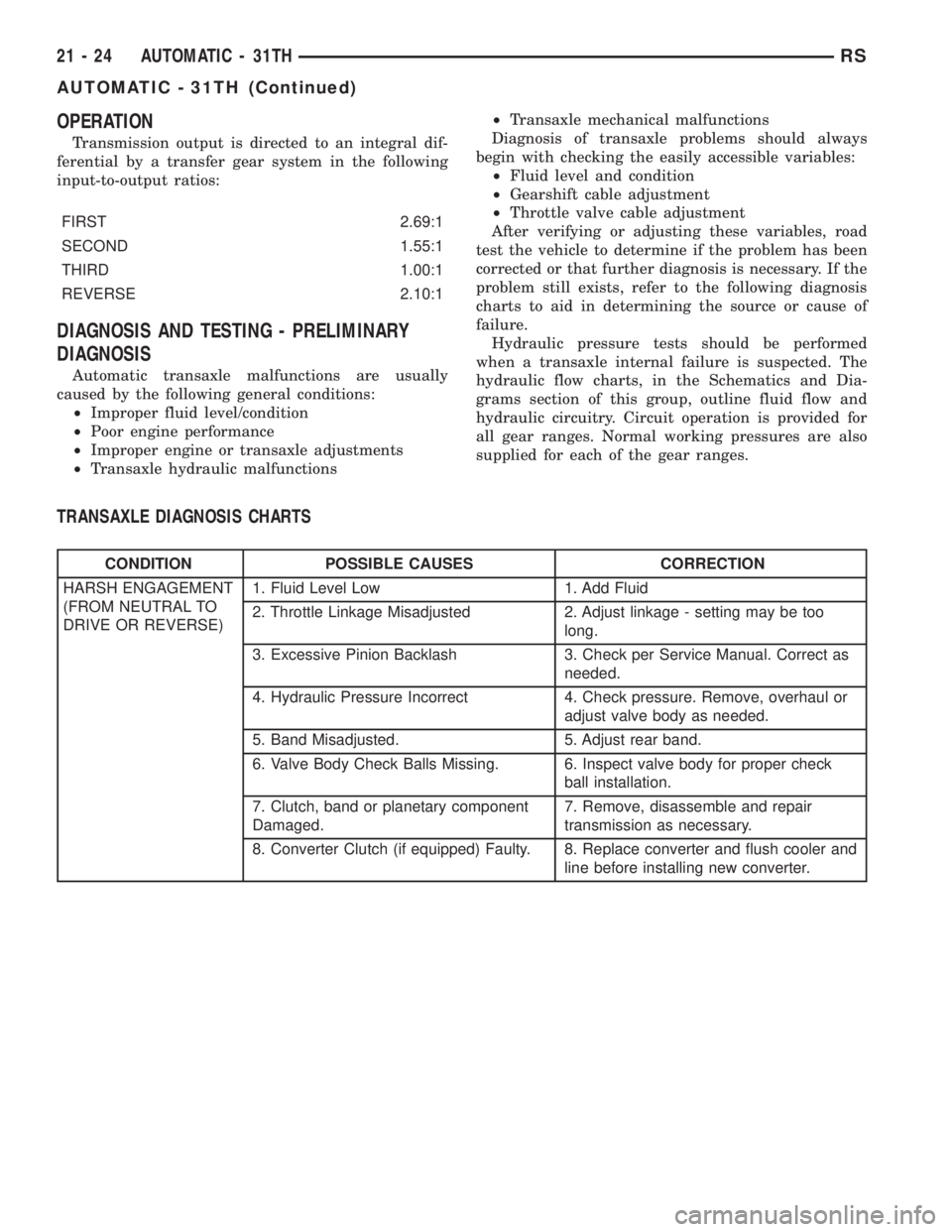
TRANSAXLE DIAGNOSIS CHARTS
CONDITION POSSIBLE CAUSES CORRECTION
HARSH ENGAGEMENT
(FROM NEUTRAL TO
DRIVE OR REVERSE)1. Fluid Level Low 1. Add Fluid
2. Throttle Linkage Misadjusted 2. Adjust linkage - setting may be too
long.
3. Excessive Pinion Backlash 3. Check per Service Manual. Correct as
needed.
4. Hydraulic Pressure Incorrect 4. Check pressure. Remove, overhaul or
adjust valve body as needed.
5. Band Misadjusted. 5. Adjust rear band.
6. Valve Body Check Balls Missing. 6. Inspect valve body for proper check
ball installation.
7. Clutch, band or planetary component
Damaged.7. Remove, disassemble and repair
transmission as necessary.
8. Converter Clutch (if equipped) Faulty. 8. Replace converter and flush cooler and
line before installing new converter.
21 - 24 AUTOMATIC - 31THRS
AUTOMATIC - 31TH (Continued)
Page 2989 of 4284
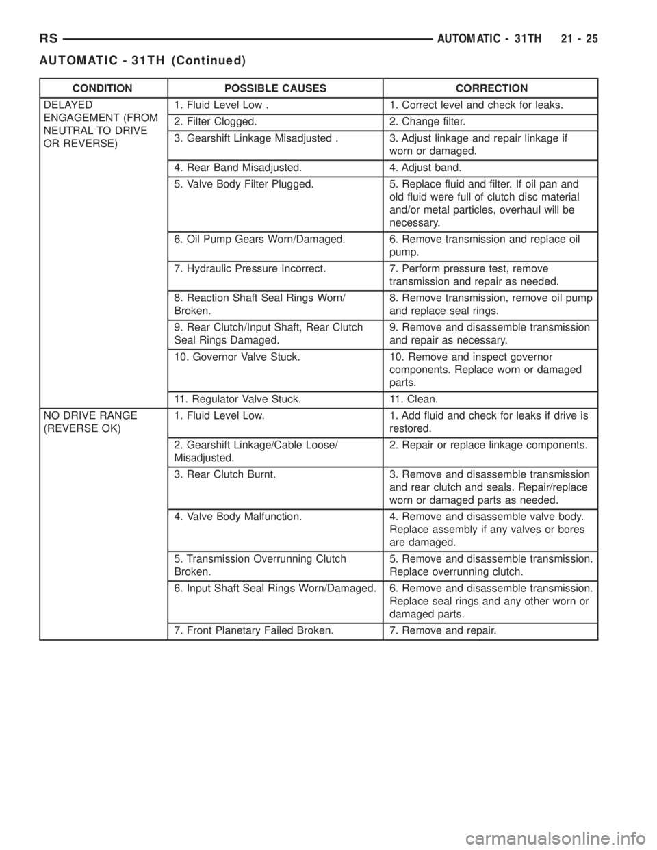
CONDITION POSSIBLE CAUSES CORRECTION
DELAYED
ENGAGEMENT (FROM
NEUTRAL TO DRIVE
OR REVERSE)1. Fluid Level Low . 1. Correct level and check for leaks.
2. Filter Clogged. 2. Change filter.
3. Gearshift Linkage Misadjusted . 3. Adjust linkage and repair linkage if
worn or damaged.
4. Rear Band Misadjusted. 4. Adjust band.
5. Valve Body Filter Plugged. 5. Replace fluid and filter. If oil pan and
old fluid were full of clutch disc material
and/or metal particles, overhaul will be
necessary.
6. Oil Pump Gears Worn/Damaged. 6. Remove transmission and replace oil
pump.
7. Hydraulic Pressure Incorrect. 7. Perform pressure test, remove
transmission and repair as needed.
8. Reaction Shaft Seal Rings Worn/
Broken.8. Remove transmission, remove oil pump
and replace seal rings.
9. Rear Clutch/Input Shaft, Rear Clutch
Seal Rings Damaged.9. Remove and disassemble transmission
and repair as necessary.
10. Governor Valve Stuck. 10. Remove and inspect governor
components. Replace worn or damaged
parts.
11. Regulator Valve Stuck. 11. Clean.
NO DRIVE RANGE
(REVERSE OK)1. Fluid Level Low. 1. Add fluid and check for leaks if drive is
restored.
2. Gearshift Linkage/Cable Loose/
Misadjusted.2. Repair or replace linkage components.
3. Rear Clutch Burnt. 3. Remove and disassemble transmission
and rear clutch and seals. Repair/replace
worn or damaged parts as needed.
4. Valve Body Malfunction. 4. Remove and disassemble valve body.
Replace assembly if any valves or bores
are damaged.
5. Transmission Overrunning Clutch
Broken.5. Remove and disassemble transmission.
Replace overrunning clutch.
6. Input Shaft Seal Rings Worn/Damaged. 6. Remove and disassemble transmission.
Replace seal rings and any other worn or
damaged parts.
7. Front Planetary Failed Broken. 7. Remove and repair.
RSAUTOMATIC - 31TH21-25
AUTOMATIC - 31TH (Continued)
Page 2990 of 4284
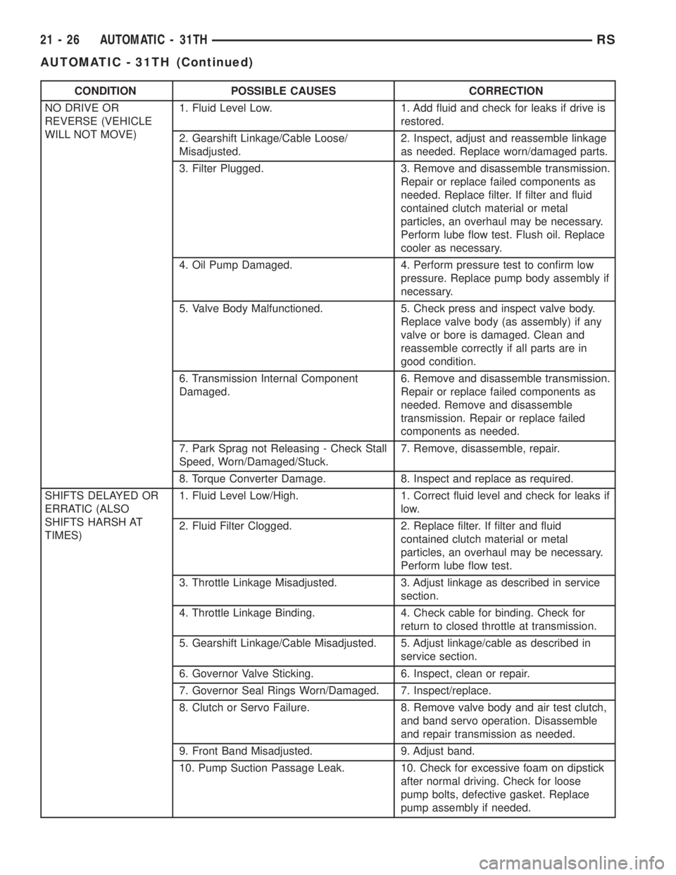
CONDITION POSSIBLE CAUSES CORRECTION
NO DRIVE OR
REVERSE (VEHICLE
WILL NOT MOVE)1. Fluid Level Low. 1. Add fluid and check for leaks if drive is
restored.
2. Gearshift Linkage/Cable Loose/
Misadjusted.2. Inspect, adjust and reassemble linkage
as needed. Replace worn/damaged parts.
3. Filter Plugged. 3. Remove and disassemble transmission.
Repair or replace failed components as
needed. Replace filter. If filter and fluid
contained clutch material or metal
particles, an overhaul may be necessary.
Perform lube flow test. Flush oil. Replace
cooler as necessary.
4. Oil Pump Damaged. 4. Perform pressure test to confirm low
pressure. Replace pump body assembly if
necessary.
5. Valve Body Malfunctioned. 5. Check press and inspect valve body.
Replace valve body (as assembly) if any
valve or bore is damaged. Clean and
reassemble correctly if all parts are in
good condition.
6. Transmission Internal Component
Damaged.6. Remove and disassemble transmission.
Repair or replace failed components as
needed. Remove and disassemble
transmission. Repair or replace failed
components as needed.
7. Park Sprag not Releasing - Check Stall
Speed, Worn/Damaged/Stuck.7. Remove, disassemble, repair.
8. Torque Converter Damage. 8. Inspect and replace as required.
SHIFTS DELAYED OR
ERRATIC (ALSO
SHIFTS HARSH AT
TIMES)1. Fluid Level Low/High. 1. Correct fluid level and check for leaks if
low.
2. Fluid Filter Clogged. 2. Replace filter. If filter and fluid
contained clutch material or metal
particles, an overhaul may be necessary.
Perform lube flow test.
3. Throttle Linkage Misadjusted. 3. Adjust linkage as described in service
section.
4. Throttle Linkage Binding. 4. Check cable for binding. Check for
return to closed throttle at transmission.
5. Gearshift Linkage/Cable Misadjusted. 5. Adjust linkage/cable as described in
service section.
6. Governor Valve Sticking. 6. Inspect, clean or repair.
7. Governor Seal Rings Worn/Damaged. 7. Inspect/replace.
8. Clutch or Servo Failure. 8. Remove valve body and air test clutch,
and band servo operation. Disassemble
and repair transmission as needed.
9. Front Band Misadjusted. 9. Adjust band.
10. Pump Suction Passage Leak. 10. Check for excessive foam on dipstick
after normal driving. Check for loose
pump bolts, defective gasket. Replace
pump assembly if needed.
21 - 26 AUTOMATIC - 31THRS
AUTOMATIC - 31TH (Continued)
Page 3045 of 4284
OPERATION
To apply the clutch, pressure is applied between
the clutch retainer and piston. The fluid pressure is
provided by the oil pump, transferred through the
control valves and passageways, and enters the
clutch through the hub of the reaction shaft support.
With pressure applied between the clutch retainer
and piston, the piston moves away from the clutch
retainer and compresses the clutch pack. This action
applies the clutch pack, allowing torque to flow
through the input shaft into the driving discs, and
into the clutch plates and pressure plate that are
lugged to the clutch retainer. The waved snap-ring is
used to cushion the application of the clutch pack. In
some transmissions, the snap-ring is selective and
used to adjust clutch pack clearance.
When pressure is released from the piston, the
spring returns the piston to its fully released position
and disengages the clutch. The release spring also
helps to cushion the application of the clutch assem-
bly. When the clutch is in the process of being
released by the release spring, fluid flows through a
vent and one-way ball-check-valve located in the
clutch retainer. The check-valve is needed to elimi-
nate the possibility of plate drag caused by centrifu-
gal force acting on the residual fluid trapped in the
clutch piston retainer.
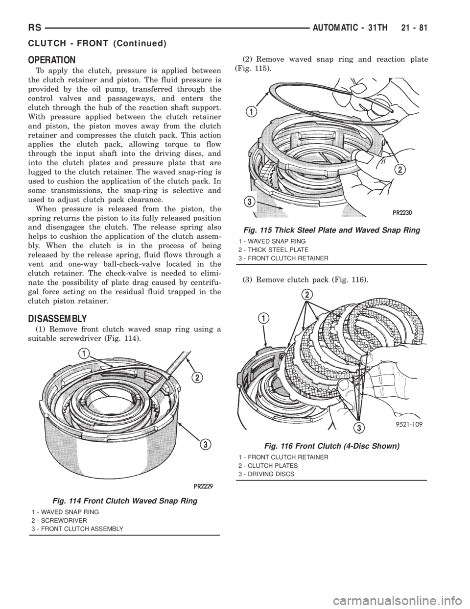
DISASSEMBLY
(1) Remove front clutch waved snap ring using a
suitable screwdriver (Fig. 114).(2) Remove waved snap ring and reaction plate
(Fig. 115).
(3) Remove clutch pack (Fig. 116).
Fig. 114 Front Clutch Waved Snap Ring
1 - WAVED SNAP RING
2 - SCREWDRIVER
3 - FRONT CLUTCH ASSEMBLY
Fig. 115 Thick Steel Plate and Waved Snap Ring
1 - WAVED SNAP RING
2 - THICK STEEL PLATE
3 - FRONT CLUTCH RETAINER
Fig. 116 Front Clutch (4-Disc Shown)
1 - FRONT CLUTCH RETAINER
2 - CLUTCH PLATES
3 - DRIVING DISCS
RSAUTOMATIC - 31TH21-81
CLUTCH - FRONT (Continued)
Page 3049 of 4284
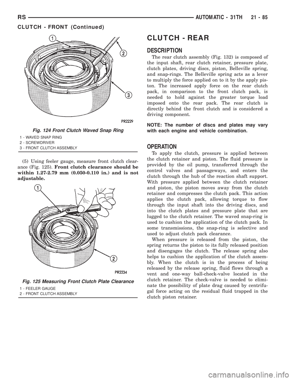
(5) Using feeler gauge, measure front clutch clear-
ance (Fig. 125).Front clutch clearance should be
within 1.27-2.79 mm (0.050-0.110 in.) and is not
adjustable.
CLUTCH - REAR
DESCRIPTION
The rear clutch assembly (Fig. 132) is composed of
the input shaft, rear clutch retainer, pressure plate,
clutch plates, driving discs, piston, Belleville spring,
and snap-rings. The Belleville spring acts as a lever
to multiply the force applied on to it by the apply pis-
ton. The increased apply force on the rear clutch
pack, in comparison to the front clutch pack, is
needed to hold against the greater torque load
imposed onto the rear pack. The rear clutch is
directly behind the front clutch and is considered a
driving component.
NOTE: The number of discs and plates may vary
with each engine and vehicle combination.
OPERATION
To apply the clutch, pressure is applied between
the clutch retainer and piston. The fluid pressure is
provided by the oil pump, transferred through the
control valves and passageways, and enters the
clutch through the hub of the reaction shaft support.
With pressure applied between the clutch retainer
and piston, the piston moves away from the clutch
retainer and compresses the clutch pack. This action
applies the clutch pack, allowing torque to flow
through the input shaft into the driving discs, and
into the clutch plates and pressure plate that are
lugged to the clutch retainer. The waved snap-ring is
used to cushion the application of the clutch pack. In
some transmissions, the snap-ring is selective and
used to adjust clutch pack clearance.
When pressure is released from the piston, the
spring returns the piston to its fully released position
and disengages the clutch. The release spring also
helps to cushion the application of the clutch assem-
bly. When the clutch is in the process of being
released by the release spring, fluid flows through a
vent and one-way ball-check-valve located in the
clutch retainer. The check-valve is needed to elimi-
nate the possibility of plate drag caused by centrifu-
gal force acting on the residual fluid trapped in the
clutch piston retainer.
Fig. 124 Front Clutch Waved Snap Ring
1 - WAVED SNAP RING
2 - SCREWDRIVER
3 - FRONT CLUTCH ASSEMBLY
Fig. 125 Measuring Front Clutch Plate Clearance
1 - FEELER GAUGE
2 - FRONT CLUTCH ASSEMBLY
RSAUTOMATIC - 31TH21-85
CLUTCH - FRONT (Continued)