2001 CHRYSLER VOYAGER check transmission fluid
[x] Cancel search: check transmission fluidPage 3303 of 4284
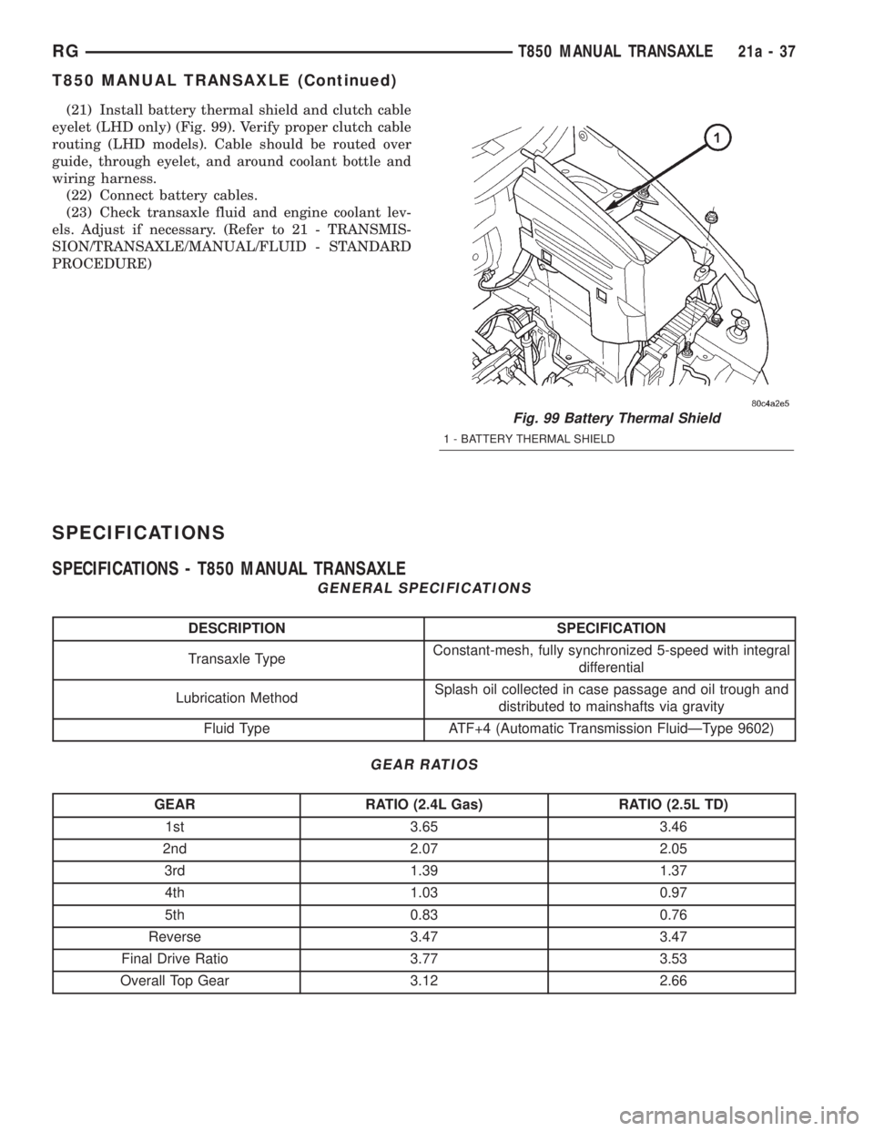
(21) Install battery thermal shield and clutch cable
eyelet (LHD only) (Fig. 99). Verify proper clutch cable
routing (LHD models). Cable should be routed over
guide, through eyelet, and around coolant bottle and
wiring harness.
(22) Connect battery cables.
(23) Check transaxle fluid and engine coolant lev-
els. Adjust if necessary. (Refer to 21 - TRANSMIS-
SION/TRANSAXLE/MANUAL/FLUID - STANDARD
PROCEDURE)
SPECIFICATIONS
SPECIFICATIONS - T850 MANUAL TRANSAXLE
GENERAL SPECIFICATIONS
DESCRIPTION SPECIFICATION
Transaxle TypeConstant-mesh, fully synchronized 5-speed with integral
differential
Lubrication MethodSplash oil collected in case passage and oil trough and
distributed to mainshafts via gravity
Fluid Type ATF+4 (Automatic Transmission FluidÐType 9602)
GEAR RATIOS
GEAR RATIO (2.4L Gas) RATIO (2.5L TD)
1st 3.65 3.46
2nd 2.07 2.05
3rd 1.39 1.37
4th 1.03 0.97
5th 0.83 0.76
Reverse 3.47 3.47
Final Drive Ratio 3.77 3.53
Overall Top Gear 3.12 2.66
Fig. 99 Battery Thermal Shield
1 - BATTERY THERMAL SHIELD
RGT850 MANUAL TRANSAXLE21a-37
T850 MANUAL TRANSAXLE (Continued)
Page 3308 of 4284
AXLE SEALS
REMOVAL
(1) Raise vehicle on hoist.
(2) Remove one or both front halfshaft assemblies.
(Refer to 3 - DIFFERENTIAL & DRIVELINE/HALF
SHAFT - REMOVAL)
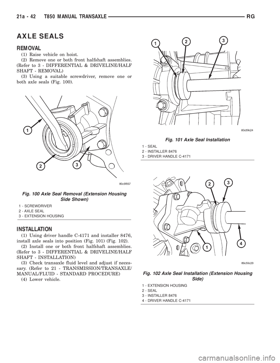
(3) Using a suitable screwdriver, remove one or
both axle seals (Fig. 100).
INSTALLATION
(1) Using driver handle C-4171 and installer 8476,
install axle seals into position (Fig. 101) (Fig. 102).
(2) Install one or both front halfshaft assemblies.
(Refer to 3 - DIFFERENTIAL & DRIVELINE/HALF
SHAFT - INSTALLATION)
(3) Check transaxle fluid level and adjust if neces-
sary. (Refer to 21 - TRANSMISSION/TRANSAXLE/
MANUAL/FLUID - STANDARD PROCEDURE)
(4) Lower vehicle.
Fig. 100 Axle Seal Removal (Extension Housing
Side Shown)
1 - SCREWDRIVER
2 - AXLE SEAL
3 - EXTENSION HOUSING
Fig. 101 Axle Seal Installation
1 - SEAL
2 - INSTALLER 8476
3 - DRIVER HANDLE C-4171
Fig. 102 Axle Seal Installation (Extension Housing
Side)
1 - EXTENSION HOUSING
2 - SEAL
3 - INSTALLER 8476
4 - DRIVER HANDLE C-4171
21a - 42 T850 MANUAL TRANSAXLERG
Page 3318 of 4284
ADJUSTMENT - DIFFERENTIAL SIDE GEAR
END PLAY
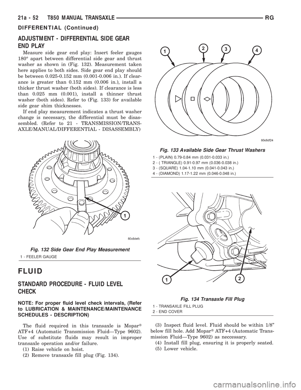
Measure side gear end play: Insert feeler gauges
180É apart between differential side gear and thrust
washer as shown in (Fig. 132). Measurement taken
here applies to both sides. Side gear end play should
be between 0.025-0.152 mm (0.001-0.006 in.). If clear-
ance is greater than 0.152 mm (0.006 in.), install a
thicker thrust washer (both sides). If clearance is less
than 0.025 mm (0.001), install a thinner thrust
washer (both sides). Refer to (Fig. 133) for available
side gear shim thicknesses.
If end play measurement indicates a thrust washer
change is necessary, the differential must be disas-
sembled. (Refer to 21 - TRANSMISSION/TRANS-
AXLE/MANUAL/DIFFERENTIAL - DISASSEMBLY)
FLUID
STANDARD PROCEDURE - FLUID LEVEL
CHECK
NOTE: For proper fluid level check intervals, (Refer
to LUBRICATION & MAINTENANCE/MAINTENANCE
SCHEDULES - DESCRIPTION)
The fluid required in this transaxle is Mopart
ATF+4 (Automatic Transmission FluidÐType 9602).
Use of substitute fluids may result in improper
transaxle operation and/or failure.
(1) Raise vehicle on hoist.
(2) Remove transaxle fill plug (Fig. 134).(3) Inspect fluid level. Fluid should be within 1/8º
below fill hole. Add MopartATF+4 (Automatic Trans-
mission FluidÐType 9602) as neccessary.
(4) Install fill plug, ensuring it is properly seated.
(5) Lower vehicle.
Fig. 132 Side Gear End Play Measurement
1 - FEELER GAUGE
Fig. 133 Available Side Gear Thrust Washers
1 - (PLAIN) 0.79-0.84 mm (0.031-0.033 in.)
2 - ( TRIANGLE) 0.91-0.97 mm (0.036-0.038 in.)
3 - (SQUARE) 1.04-1.10 mm (0.041-0.043 in.)
4 - (DIAMOND) 1.17-1.22 mm (0.046-0.048 in.)
Fig. 134 Transaxle Fill Plug
1 - TRANSAXLE FILL PLUG
2 - END COVER
21a - 52 T850 MANUAL TRANSAXLERG
DIFFERENTIAL (Continued)
Page 3699 of 4284
INSTALLATION
NOTE: If the condenser is being replaced, add 30
milliliters (1 fluid ounce) of refrigerant oil to the
refrigerant system. Use only refrigerant oil of the
type recommended for the compressor in the vehi-
cle.
NOTE: Be certain that each of the radiator and con-
denser air seals are reinstalled in their proper loca-
tions. These air seals are required in order for the
air conditioning and engine cooling systems to per-
form as designed.
(1) Position the condenser to the right mounting
bracket and transmission oil cooler unit.
(2) Position the left mounting bracket onto the side
of the condenser and transmission oil cooler.
(3) Install and tighten the one screw that secures
the left mounting bracket to the side of the transmis-
sion oil cooler. Tighten the screw to 5 N´m (45 in.
lbs.).
(4) Install and tighten the two screws that secure
each mounting bracket to the sides of the condenser.
Tighten the screws to 5 N´m (45 in. lbs.).(5) Position the condenser, transmission oil cooler,
and mounting brackets into the vehicle as a unit. Be
certain that the locating pins that secure the mount-
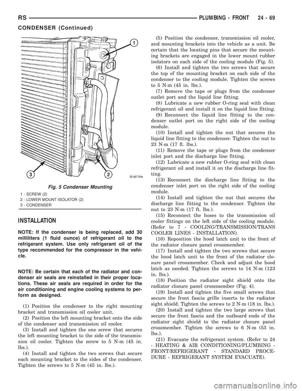
ing brackets are engaged in the lower mount rubber
isolators on each side of the cooling module (Fig. 5).
(6) Install and tighten the two screws that secure
the top of the mounting bracket on each side of the
condenser to the cooling module. Tighten the screws
to 5 N´m (45 in. lbs.).
(7) Remove the tape or plugs from the condenser
outlet port and the liquid line fitting.
(8) Lubricate a new rubber O-ring seal with clean
refrigerant oil and install it on the liquid line fitting.
(9) Reconnect the liquid line fitting to the con-
denser outlet port on the right side of the cooling
module.
(10) Install and tighten the nut that secures the
liquid line fitting to the condenser. Tighten the nut to
23 N´m (17 ft. lbs.).
(11) Remove the tape or plugs from the condenser
inlet port and the discharge line fitting.
(12) Lubricate a new rubber O-ring seal with clean
refrigerant oil and install it on the discharge line fit-
ting.
(13) Reconnect the discharge line fitting to the
condenser inlet port on the right side of the cooling
module.
(14) Install and tighten the nut that secures the
discharge line fitting to the condenser. Tighten the
nut to 23 N´m (17 ft. lbs.).
(15) Reconnect the hoses to the transmission oil
cooler fittings on the left side of the cooling module.
(Refer to 7 - COOLING/TRANSMISSION/TRANS
COOLER LINES - INSTALLATION).
(16) Reposition the hood latch unit to the front of
the radiator closure panel crossmember.
(17) Install and tighten the two screws that secure
the hood latch unit to the front of the radiator clo-
sure panel crossmember. Check and adjust the hood
latch as needed. Tighten the screws to 14 N´m (123
in. lbs.).
(18) Position the radiator sight shield onto the
radiator closure panel crossmember (Fig. 4).
(19) Install and tighten the five small screws that
secure the front fascia grille inserts to the radiator
sight shield. Tighten the screws to 2 N´m (18 in. lbs.).
(20) Install and tighten the two large screws that
secure the front fascia and the outboard ends of the
radiator sight shield to the radiator closure panel
crossmember. Tighten the screws to 6 N´m (53 in.
lbs.).
(21) Evacuate the refrigerant system. (Refer to 24
- HEATING & AIR CONDITIONING/PLUMBING -
FRONT/REFRIGERANT - STANDARD PROCE-
DURE - REFRIGERANT SYSTEM EVACUATE).
Fig. 5 Condenser Mounting
1 - SCREW (2)
2 - LOWER MOUNT ISOLATOR (2)
3 - CONDENSER
RSPLUMBING - FRONT24-69
CONDENSER (Continued)
Page 3960 of 4284
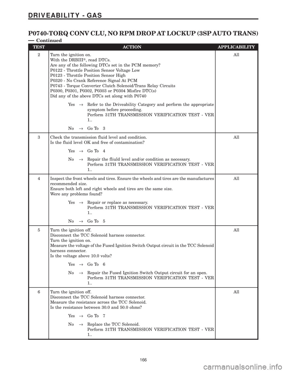
TEST ACTION APPLICABILITY
2 Turn the ignition on.
With the DRBIIIt, read DTCs.
Are any of the following DTCs set in the PCM memory?
P0122 - Throttle Position Sensor Voltage Low
P0123 - Throttle Position Sensor High
P0320 - No Crank Reference Signal At PCM
P0743 - Torque Converter Clutch Solenoid/Trans Relay Circuits
P0300, P0301, P0302, P0303 or P0304 Misfire DTC(s)
Did any of the above DTCs set along with P0740All
Ye s®Refer to the Driveability Category and perform the appropriate
symptom before proceeding.
Perform 31TH TRANSMISSION VERIFICATION TEST - VER
1..
No®Go To 3
3 Check the transmission fluid level and condition.
Is the fluid level OK and free of contamination?All
Ye s®Go To 4
No®Repair the fliuld level and/or condition as necessary.
Perform 31TH TRANSMISSION VERIFICATION TEST - VER
1..
4 Inspect the front wheels and tires. Ensure the wheels and tires are the manufactures
recommended size.
Ensure both left and right wheels and tires are the same size.
Were any problems found?All
Ye s®Repair or replace as necessary.
Perform 31TH TRANSMISSION VERIFICATION TEST - VER
1..
No®Go To 5
5 Turn the ignition off.
Disconnect the TCC Solenoid harness connector.
Turn the ignition on.
Measure the voltage of the Fused Ignition Switch Output circuit in the TCC Solenoid
harness connector.
Is the voltage above 10.0 volts?All
Ye s®Go To 6
No®Repair the Fused Ignition Switch Output circuit for an open.
Perform 31TH TRANSMISSION VERIFICATION TEST - VER
1..
6 Turn the ignition off.
Disconnect the TCC Solenoid harness connector.
Measure the resistance across the TCC Solenoid.
Is the resistance between 30.0 and 50.0 ohms?All
Ye s®Go To 7
No®Replace the TCC Solenoid.
Perform 31TH TRANSMISSION VERIFICATION TEST - VER
1..
166
DRIVEABILITY - GAS
P0740-TORQ CONV CLU, NO RPM DROP AT LOCKUP (3SP AUTO TRANS)
Ð
Continued
Page 4069 of 4284
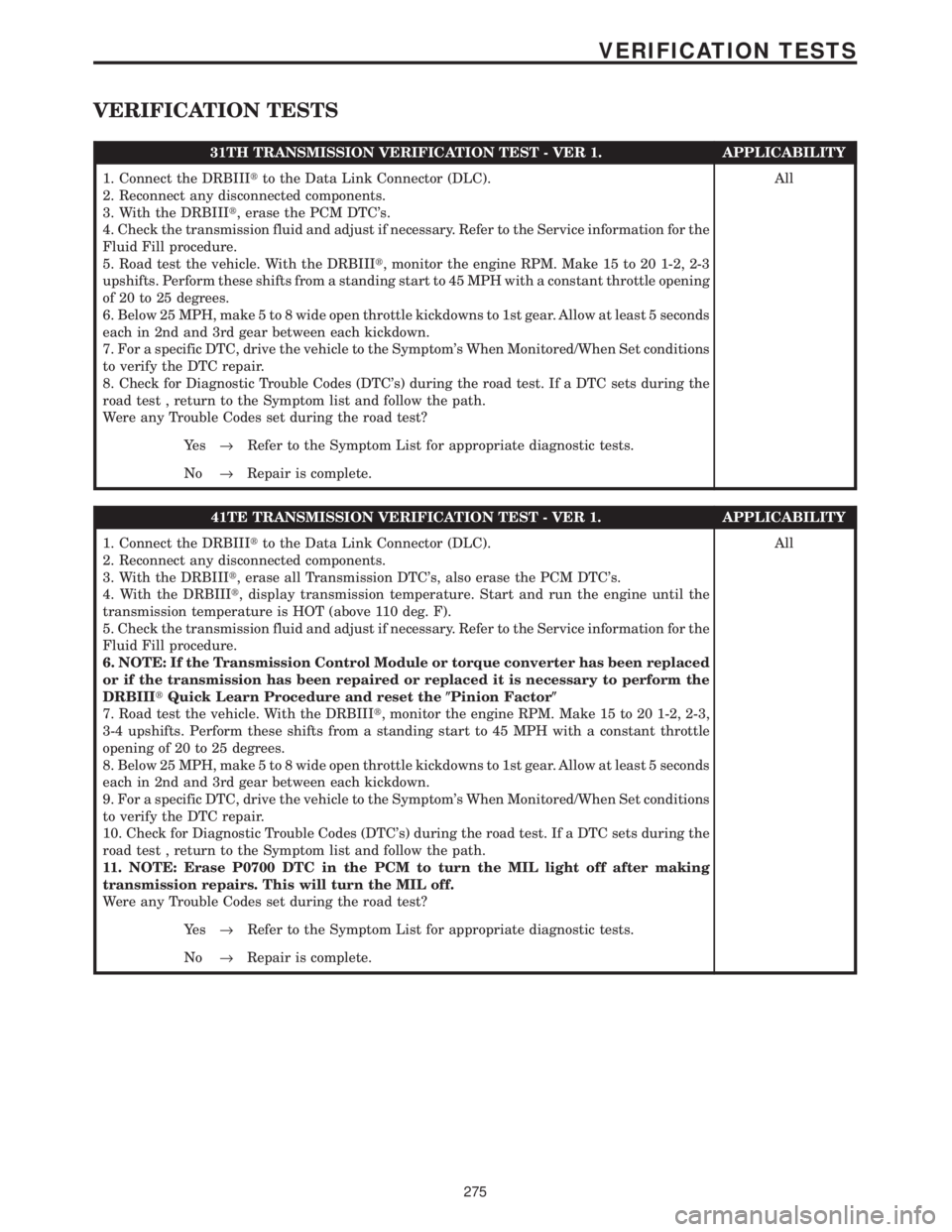
VERIFICATION TESTS
31TH TRANSMISSION VERIFICATION TEST - VER 1. APPLICABILITY
1. Connect the DRBIIItto the Data Link Connector (DLC).
2. Reconnect any disconnected components.
3. With the DRBIIIt, erase the PCM DTC's.
4. Check the transmission fluid and adjust if necessary. Refer to the Service information for the
Fluid Fill procedure.
5. Road test the vehicle. With the DRBIIIt, monitor the engine RPM. Make 15 to 20 1-2, 2-3
upshifts. Perform these shifts from a standing start to 45 MPH with a constant throttle opening
of 20 to 25 degrees.
6. Below 25 MPH, make 5 to 8 wide open throttle kickdowns to 1st gear. Allow at least 5 seconds
each in 2nd and 3rd gear between each kickdown.
7. For a specific DTC, drive the vehicle to the Symptom's When Monitored/When Set conditions
to verify the DTC repair.
8. Check for Diagnostic Trouble Codes (DTC's) during the road test. If a DTC sets during the
road test , return to the Symptom list and follow the path.
Were any Trouble Codes set during the road test?All
Ye s®Refer to the Symptom List for appropriate diagnostic tests.
No®Repair is complete.
41TE TRANSMISSION VERIFICATION TEST - VER 1. APPLICABILITY
1. Connect the DRBIIItto the Data Link Connector (DLC).
2. Reconnect any disconnected components.
3. With the DRBIIIt, erase all Transmission DTC's, also erase the PCM DTC's.
4. With the DRBIIIt, display transmission temperature. Start and run the engine until the
transmission temperature is HOT (above 110 deg. F).
5. Check the transmission fluid and adjust if necessary. Refer to the Service information for the
Fluid Fill procedure.
6. NOTE: If the Transmission Control Module or torque converter has been replaced
or if the transmission has been repaired or replaced it is necessary to perform the
DRBIIItQuick Learn Procedure and reset the(Pinion Factor(
7. Road test the vehicle. With the DRBIIIt, monitor the engine RPM. Make 15 to 20 1-2, 2-3,
3-4 upshifts. Perform these shifts from a standing start to 45 MPH with a constant throttle
opening of 20 to 25 degrees.
8. Below 25 MPH, make 5 to 8 wide open throttle kickdowns to 1st gear. Allow at least 5 seconds
each in 2nd and 3rd gear between each kickdown.
9. For a specific DTC, drive the vehicle to the Symptom's When Monitored/When Set conditions
to verify the DTC repair.
10. Check for Diagnostic Trouble Codes (DTC's) during the road test. If a DTC sets during the
road test , return to the Symptom list and follow the path.
11. NOTE: Erase P0700 DTC in the PCM to turn the MIL light off after making
transmission repairs. This will turn the MIL off.
Were any Trouble Codes set during the road test?All
Ye s®Refer to the Symptom List for appropriate diagnostic tests.
No®Repair is complete.
275
VERIFICATION TESTS
Page 4102 of 4284

TABLE OF CONTENTS - Continued
TRANSMISSION
P0120-THROTTLE POSITION SENSOR SIGNAL CIRCUIT.....................24
P0600-SERIAL COMMUNICATION LINK MALFUNCTION.......................26
P0604-INTERNAL TCM..................................................28
P0605-INTERNAL TCM..................................................29
P0700-INTERNAL TCM..................................................30
P0705-CHECK SHIFTER SIGNAL..........................................31
P0715-INPUT SPEED SENSOR ERROR....................................38
P0720-OUTPUT SPEED SENSOR ERROR..................................42
P0725-ENGINE SPEED SENSOR CIRCUIT (3.3L/3.8L)........................46
P0725-ENGINE SPEED SENSOR CIRCUIT (3.5L)............................48
P0731-GEAR RATIO ERROR IN 1ST.......................................51
P0732-GEAR RATIO ERROR IN 2ND.......................................53
P0733-GEAR RATIO ERROR IN 3RD.......................................55
P0734-GEAR RATIO ERROR IN 4TH.......................................57
P0736-GEAR RATIO ERROR IN REVERSE..................................59
P0740-TORQUE CONVERTER CLUTCH CONTROL CIRCUIT...................61
P0750-LR SOLENOID CIRCUIT............................................63
P0755-2-4 SOLENOID CIRCUIT...........................................66
P0760-OD SOLENOID CIRCUIT...........................................69
P0765-UD SOLENOID CIRCUIT...........................................72
P1714-LOW BATTERY VOLTAGE..........................................75
P1716-BUS COMMUNICATION WITH PCM..................................79
P1717-NO COMMUNICATION WITH THE MIC...............................81
P1738-HIGH TEMPERATURE OPERATION ACTIVATED.......................83
P1739-POWER UP AT SPEED............................................85
P1765-SWITCHED BATTERY.............................................86
P1767-TRANSMISSION RELAY ALWAYS ON................................89
P1768-RELAY OUTPUT ALWAYS OFF......................................92
P1775-SOLENOID SWITCH VALVE LATCHED IN TCC POSITION...............96
P1776-SOLENOID SWITCH VALVE LATCHED IN LR POSITION................100
P1781-OD PRESSURE SWITCH SENSE CIRCUIT...........................104
P1782 - 2-4 PRESSURE SWITCH SENSE CIRCUIT..........................107
P1784-LR PRESSURE SWITCH SENSE CIRCUIT...........................110
P1787-OD HYDRAULIC PRESSURE TEST FAILURE.........................114
P1788-2/4 HYDRAULIC PRESSURE TEST FAILURE.........................118
P1789-2-4/OD HYDRAULIC PRESSURE TEST FAILURE......................122
P1790-FAULT IMMEDIATELY AFTER SHIFT................................123
P1791-LOSS OF PRIME.................................................124
P1792-BATTERY WAS DISCONNECTED...................................127
P1793-TRD LINK COMMUNICATION ERROR...............................130
P1794-SPEED SENSOR GROUND ERROR................................133
P1795-INTERNAL TCM.................................................135
P1796-AUTOSTICK SENSOR CIRCUIT....................................136
P1797-MANUAL SHIFT OVERHEAT.......................................139
P1798-WORN OUT/BURNT TRANSAXLE FLUID.............................140
P1799-CALCULATED OIL TEMP IN USE...................................142
*BRAKE SHIFT INTERLOCK OUTPUT OPEN...............................146
*CHECKING PARK/NEUTRAL SWITCH OPERATION.........................148
*INCORRECT TRANSMISSION FLUID LEVEL...............................150
*NO BACK UP LAMP OPERATION........................................151
*NO SPEEDOMETER OPERATION........................................153
*TRANSMISSION NOISY WITH NO DTC'S PRESENT........................154
ii
Page 4107 of 4284
> Trailer towing in OD gear position (use 3 position
(or A/S 3rd) if frequent shifting occurs)
> Cooling system failure causing engine to operate
over 110C (230ÉF)
> Engine coolant temperature stays low too long -
If engine coolant temperature drops below 65C
(150ÉF), the transmission will disengage EMCC.
Extended operation with the EMCC disengaged
will cause the transmission to overheat.
> A brake switch issue will cause the EMCC to
disengage. Extended operation with the EMCC
disengaged will cause the transmission to over-
heat.
> Transmission fluid overfilled
> Transmission cooler or cooler lines restricted
> Transmission Temperature Sensor circuit
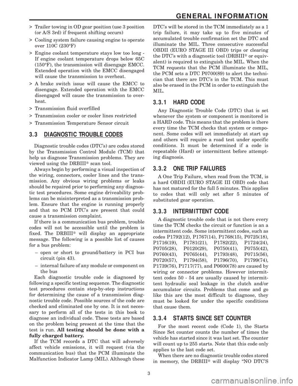
3.3 DIAGNOSTIC TROUBLE CODES
Diagnostic trouble codes (DTC's) are codes stored
by the Transmission Control Module (TCM) that
help us diagnose Transmission problems. They are
viewed using the DRBIIItscan tool.
Always begin by performing a visual inspection of
the wiring, connectors, cooler lines and the trans-
mission. Any obvious wiring problems or leaks
should be repaired prior to performing any diagnos-
tic test procedures. Some engine driveability prob-
lems can be misinterpreted as a transmission prob-
lem. Ensure that the engine is running properly
and that no PCM DTC's are present that could
cause a transmission complaint.
If there is a communication bus problem, trouble
codes will not be accessible until the problem is
fixed. The DRBIIItwill display an appropriate
message. The following is a possible list of causes
for a bus problem:
± open or short to ground/battery in PCI bus
circuit (pin 43).
± internal failure of any module or component on
the bus
Each diagnostic trouble code is diagnosed by
following a specific testing sequence. The diagnostic
test procedures contain step-by-step instructions
for determining the cause of a transmission diag-
nostic trouble code. Possible sources of the code are
checked and eliminated one by one. It is not neces-
sary to perform all of the tests in this book to
diagnose an individual code. These tests are based
on the problem being present at the time that the
test is run.All testing should be done with a
fully charged battery.
If the TCM records a DTC that will adversely
affect vehicle emissions, it will request (via the
communication bus) that the PCM illuminate the
Malfunction Indicator Lamp (MIL). Although theseDTC's will be stored in the TCM immediately as a 1
trip failure, it may take up to five minutes of
accumulated trouble confirmation set the DTC and
illuminate the MIL. Three consecutive successful
OBDII (EURO STAGE III OBD) trips or clearing
the DTC's with a diagnostic tool (DRBIIItor equiv-
alent) is required to extinguish the MIL. When the
TCM requests that the PCM illuminate the MIL,
the PCM sets a DTC P0700(89) to alert the techni-
cian that there are DTC's in the TCM. This must
also be erased in the PCM in order to extinguish the
MIL.
3.3.1 HARD CODE
Any Diagnostic Trouble Code (DTC) that is set
whenever the system or component is monitored is
a HARD code. This means that the problem is there
every time the TCM checks that system or compo-
nent. Some codes will set immediately at start up
and others will require a road test under specific
conditions. It must be determined if a code is
repeatable (Hard) or intermittent before attempt-
ing diagnosis.
3.3.2 ONE TRIP FAILURES
A One Trip Failure, when read from the TCM, is
a hard OBDII (EURO STAGE III OBD) code that
has not matured for the full 5 minutes. This applies
to codes that will only set after 5 minutes of
substituted gear operation.
3.3.3 INTERMITTENT CODE
A diagnostic trouble code that is not there every
time the TCM checks the circuit or function is an a
intermittent code. Some intermittent codes, such as
codes P1792(12), P1767(14), P1768(15), P0725(18),
P1716(19), P1781(21), P1782(22), P1724(24),
P0705(28), P0120(29), P0750(41), P0755(42),
P0760(43), P0765(44), P1793(48), P0715(56),
P0720(57), P1794(58), P1796(70), P1799(74),
P1739(76), P1717(77), and P0600(78) are caused by
wiring or connector problems. However intermit-
tent codes 50 - 54 are usually caused by intermit-
tent hydraulic seal leakage in the clutch and/or
accumulator circuits. Problems that come and go
like this are the most difficult to diagnose, they
must be looked for under the specific conditions
that cause them.
3.3.4 STARTS SINCE SET COUNTER
For the most recent code (Code 1), the Starts
Since Set counter counts the number of times the
vehicle has started since it was last set. The counter
will count up to 255 starts. Note that this code only
applies to the last code set.
When there are no diagnostic trouble codes stored
in memory, the DRBIIItwill display ``NO DTC'S
3
GENERAL INFORMATION