2001 CHRYSLER VOYAGER Memory switch input open
[x] Cancel search: Memory switch input openPage 13 of 4284

TABLE OF CONTENTS - Continued
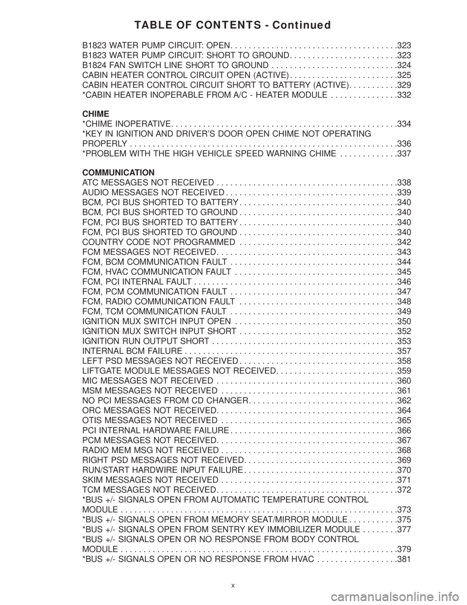
B1823 WATER PUMP CIRCUIT: OPEN.....................................323
B1823 WATER PUMP CIRCUIT: SHORT TO GROUND........................323
B1824 FAN SWITCH LINE SHORT TO GROUND............................324
CABIN HEATER CONTROL CIRCUIT OPEN (ACTIVE)........................325
CABIN HEATER CONTROL CIRCUIT SHORT TO BATTERY (ACTIVE)...........329
*CABIN HEATER INOPERABLE FROM A/C - HEATER MODULE...............332
CHIME
*CHIME INOPERATIVE..................................................334
*KEY IN IGNITION AND DRIVER'S DOOR OPEN CHIME NOT OPERATING
PROPERLY...........................................................336
*PROBLEM WITH THE HIGH VEHICLE SPEED WARNING CHIME.............337
COMMUNICATION
ATC MESSAGES NOT RECEIVED........................................338
AUDIO MESSAGES NOT RECEIVED......................................339
BCM, PCI BUS SHORTED TO BATTERY...................................340
BCM, PCI BUS SHORTED TO GROUND...................................340
FCM, PCI BUS SHORTED TO BATTERY...................................340
FCM, PCI BUS SHORTED TO GROUND...................................340
COUNTRY CODE NOT PROGRAMMED...................................342
FCM MESSAGES NOT RECEIVED........................................343
FCM, BCM COMMUNICATION FAULT.....................................344
FCM, HVAC COMMUNICATION FAULT....................................345
FCM, PCI INTERNAL FAULT.............................................346
FCM, PCM COMMUNICATION FAULT.....................................347
FCM, RADIO COMMUNICATION FAULT...................................348
FCM, TCM COMMUNICATION FAULT.....................................349
IGNITION MUX SWITCH INPUT OPEN....................................350
IGNITION MUX SWITCH INPUT SHORT...................................352
IGNITION RUN OUTPUT SHORT.........................................353
INTERNAL BCM FAILURE...............................................357
LEFT PSD MESSAGES NOT RECEIVED...................................358
LIFTGATE MODULE MESSAGES NOT RECEIVED...........................359
MIC MESSAGES NOT RECEIVED........................................360
MSM MESSAGES NOT RECEIVED.......................................361
NO PCI MESSAGES FROM CD CHANGER.................................362
ORC MESSAGES NOT RECEIVED........................................364
OTIS MESSAGES NOT RECEIVED.......................................365
PCI INTERNAL HARDWARE FAILURE.....................................366
PCM MESSAGES NOT RECEIVED........................................367
RADIO MEM MSG NOT RECEIVED.......................................368
RIGHT PSD MESSAGES NOT RECEIVED..................................369
RUN/START HARDWIRE INPUT FAILURE..................................370
SKIM MESSAGES NOT RECEIVED.......................................371
TCM MESSAGES NOT RECEIVED........................................372
*BUS +/- SIGNALS OPEN FROM AUTOMATIC TEMPERATURE CONTROL
MODULE.............................................................373
*BUS +/- SIGNALS OPEN FROM MEMORY SEAT/MIRROR MODULE...........375
*BUS +/- SIGNALS OPEN FROM SENTRY KEY IMMOBILIZER MODULE........377
*BUS +/- SIGNALS OPEN OR NO RESPONSE FROM BODY CONTROL
MODULE.............................................................379
*BUS +/- SIGNALS OPEN OR NO RESPONSE FROM HVAC..................381
x
Page 17 of 4284

TABLE OF CONTENTS - Continued
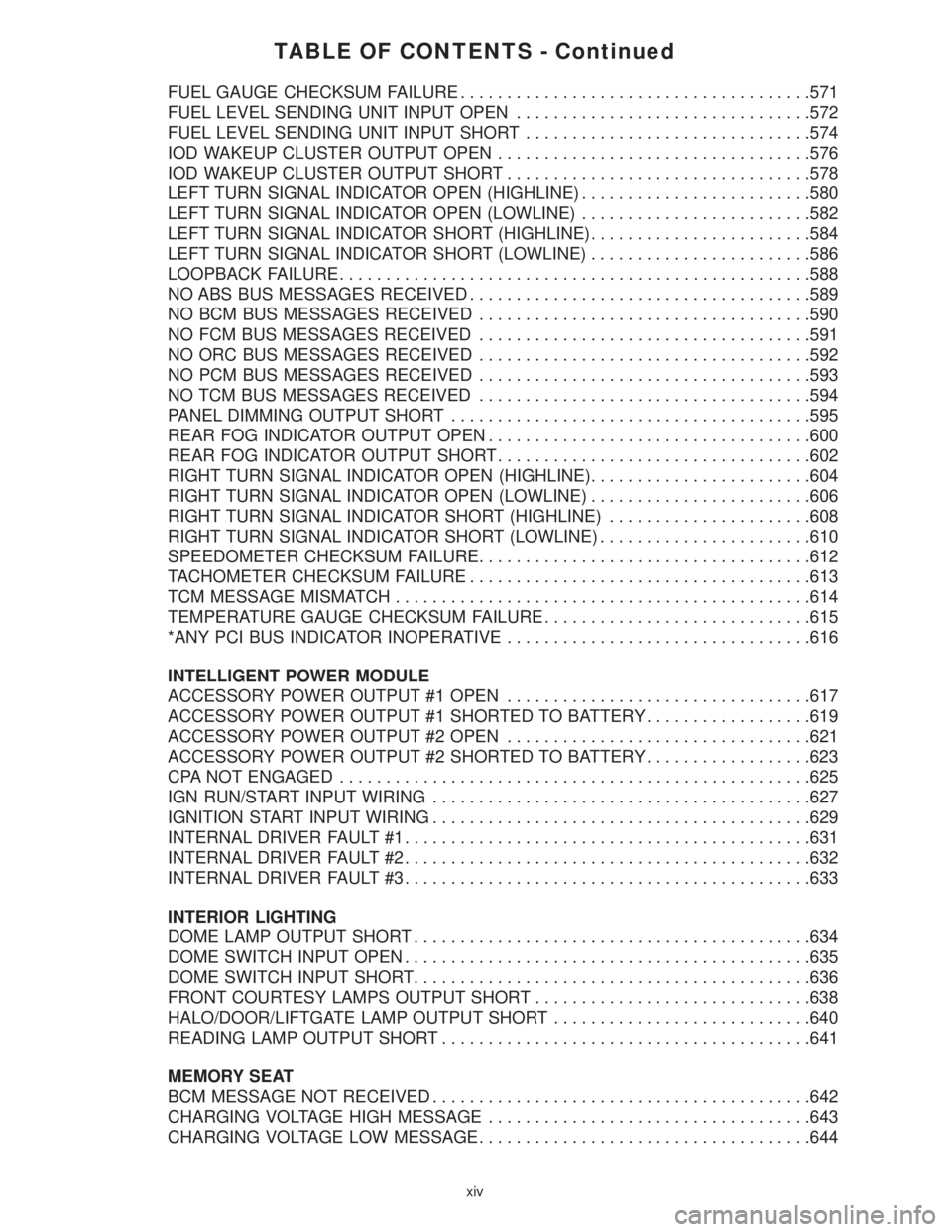
FUEL GAUGE CHECKSUM FAILURE......................................571
FUEL LEVEL SENDING UNIT INPUT OPEN................................572
FUEL LEVEL SENDING UNIT INPUT SHORT...............................574
IOD WAKEUP CLUSTER OUTPUT OPEN..................................576
IOD WAKEUP CLUSTER OUTPUT SHORT.................................578
LEFT TURN SIGNAL INDICATOR OPEN (HIGHLINE).........................580
LEFT TURN SIGNAL INDICATOR OPEN (LOWLINE).........................582
LEFT TURN SIGNAL INDICATOR SHORT (HIGHLINE)........................584
LEFT TURN SIGNAL INDICATOR SHORT (LOWLINE)........................586
LOOPBACK FAILURE...................................................588
NO ABS BUS MESSAGES RECEIVED.....................................589
NO BCM BUS MESSAGES RECEIVED....................................590
NO FCM BUS MESSAGES RECEIVED....................................591
NO ORC BUS MESSAGES RECEIVED....................................592
NO PCM BUS MESSAGES RECEIVED....................................593
NO TCM BUS MESSAGES RECEIVED....................................594
PANEL DIMMING OUTPUT SHORT.......................................595
REAR FOG INDICATOR OUTPUT OPEN...................................600
REAR FOG INDICATOR OUTPUT SHORT..................................602
RIGHT TURN SIGNAL INDICATOR OPEN (HIGHLINE)........................604
RIGHT TURN SIGNAL INDICATOR OPEN (LOWLINE)........................606
RIGHT TURN SIGNAL INDICATOR SHORT (HIGHLINE)......................608
RIGHT TURN SIGNAL INDICATOR SHORT (LOWLINE).......................610
SPEEDOMETER CHECKSUM FAILURE....................................612
TACHOMETER CHECKSUM FAILURE.....................................613
TCM MESSAGE MISMATCH.............................................614
TEMPERATURE GAUGE CHECKSUM FAILURE.............................615
*ANY PCI BUS INDICATOR INOPERATIVE.................................616
INTELLIGENT POWER MODULE
ACCESSORY POWER OUTPUT #1 OPEN.................................617
ACCESSORY POWER OUTPUT #1 SHORTED TO BATTERY..................619
ACCESSORY POWER OUTPUT #2 OPEN.................................621
ACCESSORY POWER OUTPUT #2 SHORTED TO BATTERY..................623
CPA NOT ENGAGED...................................................625
IGN RUN/START INPUT WIRING.........................................627
IGNITION START INPUT WIRING.........................................629
INTERNAL DRIVER FAULT #1............................................631
INTERNAL DRIVER FAULT #2............................................632
INTERNAL DRIVER FAULT #3............................................633
INTERIOR LIGHTING
DOME LAMP OUTPUT SHORT...........................................634
DOME SWITCH INPUT OPEN............................................635
DOME SWITCH INPUT SHORT...........................................636
FRONT COURTESY LAMPS OUTPUT SHORT..............................638
HALO/DOOR/LIFTGATE LAMP OUTPUT SHORT............................640
READING LAMP OUTPUT SHORT........................................641
MEMORY SEAT
BCM MESSAGE NOT RECEIVED.........................................642
CHARGING VOLTAGE HIGH MESSAGE...................................643
CHARGING VOLTAGE LOW MESSAGE....................................644
xiv
Page 18 of 4284

TABLE OF CONTENTS - Continued
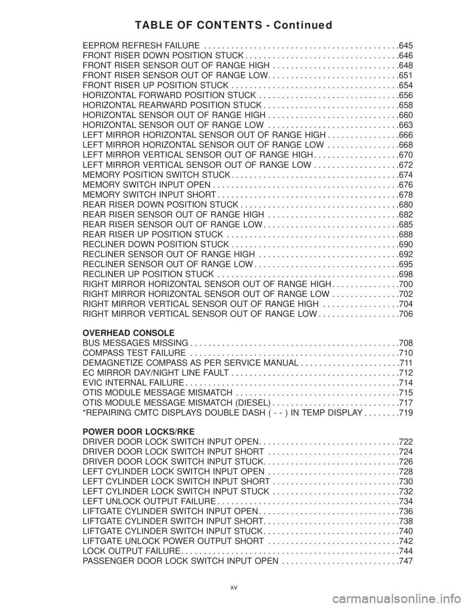
EEPROM REFRESH FAILURE...........................................645
FRONT RISER DOWN POSITION STUCK..................................646
FRONT RISER SENSOR OUT OF RANGE HIGH............................648
FRONT RISER SENSOR OUT OF RANGE LOW.............................651
FRONT RISER UP POSITION STUCK.....................................654
HORIZONTAL FORWARD POSITION STUCK...............................656
HORIZONTAL REARWARD POSITION STUCK..............................658
HORIZONTAL SENSOR OUT OF RANGE HIGH.............................660
HORIZONTAL SENSOR OUT OF RANGE LOW.............................663
LEFT MIRROR HORIZONTAL SENSOR OUT OF RANGE HIGH................666
LEFT MIRROR HORIZONTAL SENSOR OUT OF RANGE LOW................668
LEFT MIRROR VERTICAL SENSOR OUT OF RANGE HIGH...................670
LEFT MIRROR VERTICAL SENSOR OUT OF RANGE LOW...................672
MEMORY POSITION SWITCH STUCK.....................................674
MEMORY SWITCH INPUT OPEN.........................................676
MEMORY SWITCH INPUT SHORT........................................678
REAR RISER DOWN POSITION STUCK...................................680
REAR RISER SENSOR OUT OF RANGE HIGH.............................682
REAR RISER SENSOR OUT OF RANGE LOW..............................685
REAR RISER UP POSITION STUCK......................................688
RECLINER DOWN POSITION STUCK.....................................690
RECLINER SENSOR OUT OF RANGE HIGH...............................692
RECLINER SENSOR OUT OF RANGE LOW................................695
RECLINER UP POSITION STUCK........................................698
RIGHT MIRROR HORIZONTAL SENSOR OUT OF RANGE HIGH...............700
RIGHT MIRROR HORIZONTAL SENSOR OUT OF RANGE LOW...............702
RIGHT MIRROR VERTICAL SENSOR OUT OF RANGE HIGH.................704
RIGHT MIRROR VERTICAL SENSOR OUT OF RANGE LOW..................706
OVERHEAD CONSOLE
BUS MESSAGES MISSING..............................................708
COMPASS TEST FAILURE..............................................710
DEMAGNETIZE COMPASS AS PER SERVICE MANUAL......................711
EC MIRROR DAY/NIGHT LINE FAULT.....................................712
EVIC INTERNAL FAILURE...............................................714
OTIS MODULE MESSAGE MISMATCH....................................715
OTIS MODULE MESSAGE MISMATCH (DIESEL)............................717
*REPAIRING CMTC DISPLAYS DOUBLE DASH(--)INTEMP DISPLAY........719
POWER DOOR LOCKS/RKE
DRIVER DOOR LOCK SWITCH INPUT OPEN...............................722
DRIVER DOOR LOCK SWITCH INPUT SHORT.............................724
DRIVER DOOR LOCK SWITCH INPUT STUCK..............................726
LEFT CYLINDER LOCK SWITCH INPUT OPEN.............................728
LEFT CYLINDER LOCK SWITCH INPUT SHORT............................730
LEFT CYLINDER LOCK SWITCH INPUT STUCK............................732
LEFT UNLOCK OUTPUT FAILURE........................................734
LIFTGATE CYLINDER SWITCH INPUT OPEN...............................736
LIFTGATE CYLINDER SWITCH INPUT SHORT..............................738
LIFTGATE CYLINDER SWITCH INPUT STUCK..............................740
LIFTGATE UNLOCK POWER OUTPUT SHORT.............................742
LOCK OUTPUT FAILURE................................................744
PASSENGER DOOR LOCK SWITCH INPUT OPEN..........................747
xv
Page 51 of 4284

On vehicles equipped with AutoStick, the display
includes an O/D OFF indicator that is illuminated
when the driver presses the Overdrive Off button
on the transaxle shifter.
3.11.1 INSTRUMENT CLUSTER SELF TEST
1. Depress and hold the Odometer Reset button.
2. Turn the ignition switch to the RUN/START
position.
3. Release the Odometer reset button.
The Instrument Cluster will illuminate all indi-
cators and step the gauges through several calibra-
tion points. Also, the odometer will display any
stored codes that may have set.
3.11.2 MESSAGE CENTER
The Message Center is located above the brow of
the Instrument Cluster. It houses the following
warning indicators: Check Engine/Service Engine
Soon, high beam, left and right turn signals, Secu-
rity Alarm Set, and low oil pressure. On base
models equipped with the three-speed transaxle,
these indicators appear in the face of the cluster.
The Security Alarm set indicator is a red circle.
Activation of Instrument Cluster indicators is
coordinated with indicators in the message center
and EVIC to avoid redundancy. A revised safety
standard now requires that the seat belt warning
lamp in the Instrument Cluster remain lit if the
driver seat belt is not buckled. A headlamp out ISO
indicator has been added to the Instrument Cluster
to alert the driver when a headlamp is not function-
ing.
3.12 INTERIOR LIGHTING
3.12.1 COURTESY LAMP CONTROL
The body controller has direct control over all of
the vehicle's courtesy lamps. The body computer
will illuminate the courtesy lamps under any of the
following conditions:
1. Any door ajar and courtesy lamp switch on the
headlamp switch is not in the dome off position.
2. The courtesy lamp switch on the headlamp
switch is in the dome on position.
3. A Remote Keyless Entry unlock message is re-
ceived.
4. Driver door unlocked with key (with VTSS only).
3.12.2 ILLUMINATED ENTRY
Illuminated entry will be initiated when the cus-
tomer enters the vehicle by unlocking the doors
with the key fob, or with the key if the vehicle is
equipped with vehicle theft alarm. Upon exiting thevehicle, if the lock button is pressed with a door
open, illuminated entry will cancel when the door
closes. If the doors are closed and the ignition
switch is turned on, the illuminated entry also
cancels. The illuminated entry feature will not
operate if the courtesy lamp switch is in the dome
off position.
3.12.3 INTERIOR LIGHTING BATTERY
SAVER
If any of the interior lamps are left on after the
ignition is turned off, the BCM will turn them off
after 8 minutes. To return to normal operation, the
courtesy lamps will operate after the dome lamp
switch or door ajar switch changes state. The glove
box and switched reading lamps require that the
ignition be turned to the on/acc position.
3.13 MEMORY SYSTEM
The memory system consists of power driver 's
seat, power mirrors and radio presets. The Memory
Seat/Mirror Module (MSMM) is located under the
driver 's seat. It receives input from the following:
driver 's manual 8-way seat switch, driver 's seat
position sensors, PCI bus circuits, and the power
mirror sensors. The module uses these inputs to
perform the following functions: position the driv-
er 's memory seat, both exterior mirrors (during
recalls), and send/receive the memory system infor-
mation over the PCI bus.
The Memory Set Switch is wired to the Body
Control Module (BCM). When a button (either #1 or
#2) is pressed on the set switch causes the to BCM
send a message to the MSMM which in turn sends
a motion status messages to the BCM. If the BCM
receives no motion from the MSMM it will send a
recall message to the MSMM and radio (once igni-
tion is in run or accessory). The MSMM will in turn
position the drivers seat, both mirrors along with
recalling the radio presets. If the drivers seat or
either exterior mirror is inoperative from its own
respective switches, use the service information
and schematic to diagnose the problem. This man-
ual addresses the memory problems only and it is
assumed there is not a basic component failure.
3.13.1 POWER SEAT
The memory power seat provides the driver with
2 position settings for the driver 's seat. Each power
seat motor is connected to the MSMM with two
motor drive circuits. Each circuit is switched be-
tween battery and ground. By being able to bi-
directionally drive the circuits, the MSMM controls
the movement of the motors based on input from
the power seat switch or from the position sensors
when performing a memory recall. Each motor
22
GENERAL INFORMATION
Page 53 of 4284

seconds instead of 5, the CMTC will set the
variance to 8 and enter the fast calibration
mode.
3. The VAR light will come on and the last variance
setting will be displayed.
4. Press the STEP button to set the zone number.
5. Press the US/M button and resume normal op-
eration.
NOTE: Do not attach any magnetic device
such as a magnetic CB antenna to the
vehicle. This can cause the compass to give
false readings.
3.15 POWER DOOR LOCK SYSTEM
When the BCM receives input for a lock request
from a door lock switch, RKE or cylinder lock switch
(only with VTSS), it will turn the lock driver on for
a specified time of 375 msec. If the request is there
beyond 375 msec, the BCM considers the door lock
signal stuck. Once a door lock or unlock signal is
stuck for longer than 10 seconds, the BCM will set
a trouble code and the signal input is ignored until
the stuck condition disappears. The door lock
switches provide a variable amount of resistance
thereby dropping the voltage of the multiplexed
(MUX) circuit and the BCM will respond to that
command.
3.15.1 SLIDING DOOR MEMORY LOCK
When the BCM receives an input for a lock
request and a sliding door is open, the BCM will
turn on the lock driver as described above, and will
turn it on again when all sliding doors are closed.
NOTE: If the BCM receives an unlock input before
a sliding door is closed, this will cancel the memory
lock.
3.15.2 DOOR LOCK INHIBIT
When the key is in the ignition and in any
position and either front door is open, the door lock
switches LOCK functions are disabled. The UN-
LOCK functions are still functional. This protects
against locking the vehicle with the keys still in the
ignition. The RKE key fob will still lock the doors as
usual. This allows the driver to lock the vehicle with
the engine running for warm up.
3.15.3 AUTOMATIC DOOR LOCKS
This feature can be enabled or disabled by using
either the DRBIIItor the customer programming
method. When enabled all the doors will lock when
the vehicle reaches a speed of 18 MPH (29 KMH)
and all the doors are closed. If a door is opened and
the vehicle slows to below 18 MPH (29 KMH), thedoor locks will operate again once all doors are
closed and the speed is above 15 MPH (24 KMH).
3.15.4 REMOTE KEYLESS ENTRY (RKE)
The body control module interfaces with the RKE
module via a one-way serial bus interface. The RKE
module is not on the PCI bus. The RKE module
sends a 0-5 volt pulse width signal to the BCM
depending on which button on the transmitter was
pressed. The BCM controls the door lock/unlock
functions and the arming/disarming of the Vehicle
Theft Security System (if equipped) and the activa-
tion of illuminated entry. The BCM will also send
the appropriate messages to the Power Sliding
Doors and Power Liftgate modules. The Intelligent
Power Module (IPM) activates the park lamps,
headlamps, and horn for horn chirp when sent the
appropriate message from the BCM as received
from the RKE transmitter. When a one-button
press is made for unlock, both driver side doors will
unlock and the front and rear turn signal will flash.
When a second press is initiated (within 5 seconds
of the first) both passenger doors will unlock and all
four turn signals will flash.
The RKE module is capable of retaining up to 4
individual access codes (4 transmitters). If the
PRNDL is in any position except park, the BCM will
ground the interface thereby disabling the RKE.
The 2 button transmitter will have 2-CR2016
batteries in series. The 5 button transmitter will
have 1-CR2016 battery. The minimum battery life
should be approximately 4.7 years based on 20
transmissions a day at 84ÉF (25ÉC). Using the
DRBIIItand selecting RKE FOB Test can test the
transmitter.
The RKE module can be programmed via the
DRBIIItor the customer programming method.
The BCM will only allow programming mode to be
entered when the ignition is in the on position, the
PRNDL is in park position, and the VTSS (if
equipped) is in the disarmed mode.
3.16 POWER FOLDING MIRRORS
The power folding mirrors are powered to two
positions: folded and unfolded. The driver may
choose fold or unfold with a switch that is located on
the right side of the steering column. The folding
mirror switch grounds a sense wire that comes from
the Body Control Module when it is placed in the
fold position. The mirrors will move to the position
designated by the switch whether the ignition
switch is the On or Off position and both front doors
are closed. When the Power Folding Mirror switch
is left in the fold position during a vehicle exit the
mirrors will automatically unfold then refold after
both front doors are closed. This is to prevent mirror
contact with either front door when opened. When
24
GENERAL INFORMATION
Page 705 of 4284

Symptom:
MEMORY SWITCH INPUT OPEN
When Monitored and Set Condition:
MEMORY SWITCH INPUT OPEN
When Monitored: Continuously when the PCI bus is active.
Set Condition: If the Memory Set switch voltage is greater than 4.8 volts for over 10
seconds.
POSSIBLE CAUSES
DTC PRESENT
MEMORY SET SWITCH OPEN
MEMORY SELECT SWITCH MUX OPEN
MEMORY SELECT SWITCH RETURN OPEN
BODY CONTROL MODULE
TEST ACTION APPLICABILITY
1 With the DRBIIIt, record and erase DTC's.
Cycle the ignition OFF then back ON.
With the DRBIIIt, read DTCs.
Operate the Memory Set switch several times while monitoring the DRBIII.
Does the DRBIIItdisplay MEMORY SWITCH INPUT OPEN?All
Ye s®Go To 2
No®Using the wiring diagram/schematic as a guide, inspect the
wiring and connectors for an intermittent condition.
Perform MEMORY SYSTEM VERIFICATION TEST - VER 1.
2 Disconnect the Memory Set Switch connector
Turn the ignition on.
Connect a jumper wire between Memory Select Switch MUX and Memory Select
Switch Return.
With the DRBIIItin Sensors, read the Memory Select SW Volts.
Is the voltage below 1.0 volt?All
Ye s®Replace the Memory Set Switch.
Perform MEMORY SYSTEM VERIFICATION TEST - VER 1.
No®Go To 3
676
MEMORY SEAT
Page 706 of 4284

TEST ACTION APPLICABILITY
3 Turn the ignition off.
Disconnect the Memory Set switch connector.
Disconnect the BCM C1 harness connector.
Measure the resistance of the Memory Select Switch MUX circuit between the
Memory Set Switch connector and the BCM C1 connector.
Is the resistance below 5.0 ohms?All
Ye s®Go To 4
No®Repair the Memory Select Switch MUX circuit for an open.
Perform MEMORY SYSTEM VERIFICATION TEST - VER 1.
4 Turn the ignition off.
Disconnect the Memory Set switch connector.
Disconnect the BCM C1 harness connector.
Measure the resistance of the Memory Select Switch Return circuit between the
Memory Set Switch connector and the BCM C1 connector.
Is the resistance below 5.0 ohms?All
Ye s®Go To 5
No®Repair the Memory Select Switch Return circuit for an open.
Perform MEMORY SYSTEM VERIFICATION TEST - VER 1.
5 If there are no possible causes remaining, view repair. All
Repair
Replace the Body Control Module.
Perform MEMORY SYSTEM VERIFICATION TEST - VER 1.
677
MEMORY SEAT
MEMORY SWITCH INPUT OPEN ÐContinued
Page 1221 of 4284

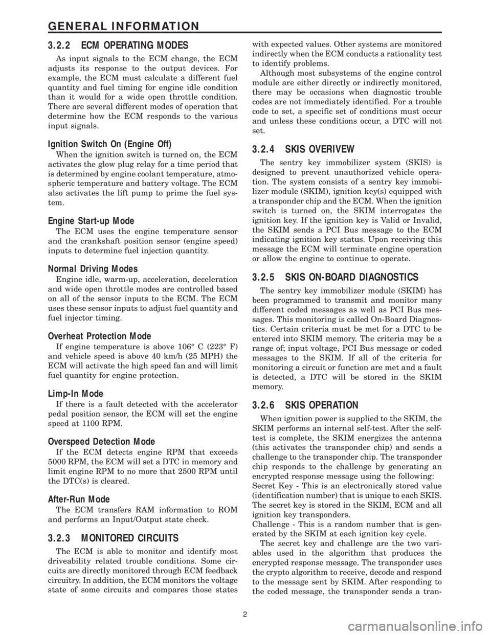
3.2.2 ECM OPERATING MODES
As input signals to the ECM change, the ECM
adjusts its response to the output devices. For
example, the ECM must calculate a different fuel
quantity and fuel timing for engine idle condition
than it would for a wide open throttle condition.
There are several different modes of operation that
determine how the ECM responds to the various
input signals.
Ignition Switch On (Engine Off)
When the ignition switch is turned on, the ECM
activates the glow plug relay for a time period that
is determined by engine coolant temperature, atmo-
spheric temperature and battery voltage. The ECM
also activates the lift pump to prime the fuel sys-
tem.
Engine Start-up Mode
The ECM uses the engine temperature sensor
and the crankshaft position sensor (engine speed)
inputs to determine fuel injection quantity.
Normal Driving Modes
Engine idle, warm-up, acceleration, deceleration
and wide open throttle modes are controlled based
on all of the sensor inputs to the ECM. The ECM
uses these sensor inputs to adjust fuel quantity and
fuel injector timing.
Overheat Protection Mode
If engine temperature is above 106É C (223É F)
and vehicle speed is above 40 km/h (25 MPH) the
ECM will activate the high speed fan and will limit
fuel quantity for engine protection.
Limp-In Mode
If there is a fault detected with the accelerator
pedal position sensor, the ECM will set the engine
speed at 1100 RPM.
Overspeed Detection Mode
If the ECM detects engine RPM that exceeds
5000 RPM, the ECM will set a DTC in memory and
limit engine RPM to no more that 2500 RPM until
the DTC(s) is cleared.
After-Run Mode
The ECM transfers RAM information to ROM
and performs an Input/Output state check.
3.2.3 MONITORED CIRCUITS
The ECM is able to monitor and identify most
driveability related trouble conditions. Some cir-
cuits are directly monitored through ECM feedback
circuitry. In addition, the ECM monitors the voltage
state of some circuits and compares those stateswith expected values. Other systems are monitored
indirectly when the ECM conducts a rationality test
to identify problems.
Although most subsystems of the engine control
module are either directly or indirectly monitored,
there may be occasions when diagnostic trouble
codes are not immediately identified. For a trouble
code to set, a specific set of conditions must occur
and unless these conditions occur, a DTC will not
set.
3.2.4 SKIS OVERIVEW
The sentry key immobilizer system (SKIS) is
designed to prevent unauthorized vehicle opera-
tion. The system consists of a sentry key immobi-
lizer module (SKIM), ignition key(s) equipped with
a transponder chip and the ECM. When the ignition
switch is turned on, the SKIM interrogates the
ignition key. If the ignition key is Valid or Invalid,
the SKIM sends a PCI Bus message to the ECM
indicating ignition key status. Upon receiving this
message the ECM will terminate engine operation
or allow the engine to continue to operate.
3.2.5 SKIS ON-BOARD DIAGNOSTICS
The sentry key immobilizer module (SKIM) has
been programmed to transmit and monitor many
different coded messages as well as PCI Bus mes-
sages. This monitoring is called On-Board Diagnos-
tics. Certain criteria must be met for a DTC to be
entered into SKIM memory. The criteria may be a
range of; input voltage, PCI Bus message or coded
messages to the SKIM. If all of the criteria for
monitoring a circuit or function are met and a fault
is detected, a DTC will be stored in the SKIM
memory.
3.2.6 SKIS OPERATION
When ignition power is supplied to the SKIM, the
SKIM performs an internal self-test. After the self-
test is complete, the SKIM energizes the antenna
(this activates the transponder chip) and sends a
challenge to the transponder chip. The transponder
chip responds to the challenge by generating an
encrypted response message using the following:
Secret Key - This is an electronically stored value
(identification number) that is unique to each SKIS.
The secret key is stored in the SKIM, ECM and all
ignition key transponders.
Challenge - This is a random number that is gen-
erated by the SKIM at each ignition key cycle.
The secret key and challenge are the two vari-
ables used in the algorithm that produces the
encrypted response message. The transponder uses
the crypto algorithm to receive, decode and respond
to the message sent by SKIM. After responding to
the coded message, the transponder sends a tran-
2
GENERAL INFORMATION