2001 CHRYSLER VOYAGER Memory switch input open
[x] Cancel search: Memory switch input openPage 1828 of 4284

The normal base braking system will remain opera-
tional.
NOTE: If the vehicle is equipped with traction con-
trol, the TRAC OFF lamp will illuminate anytime the
amber ABS warning indicator lamp illuminates.
The CAB continuously monitors the speed of each
wheel through the signals generated by the wheel
speed sensors to determine if any wheel is beginning
to lock. When a wheel locking tendency is detected,
the CAB commands the CAB command coils to actu-
ate. The coils then open and close the valves in the
HCU that modulate brake fluid pressure in some or
all of the hydraulic circuits. The CAB continues to
control pressure in individual hydraulic circuits until
a locking tendency is no longer present.
The CAB contains a self-diagnostic program that
monitors the antilock brake system for system faults.
When a fault is detected, the amber ABS warning
indicator lamp is turned on and the fault diagnostic
trouble code (DTC) is then stored in a diagnostic pro-
gram memory. These DTC's will remain in the CAB
memory even after the ignition has been turned off.
The DTC's can be read and cleared from the CAB
memory by a technician using the DRBIIItscan tool.
If not cleared with a DRBIIItscan tool, the fault
occurrence and DTC will be automatically cleared
from the CAB memory after the identical fault has
not been seen during the next 3,500 miles.
CAB INPUTS
²Wheel speed sensors (four)
²Brake lamp switch
²Ignition switch
²System and pump voltage
²Ground
²Traction control switch (if equipped)
²Diagnostic communication (PCI)
CAB OUTPUTS
²Amber ABS warning indicator lamp actuation
(via BUS)
²Instrument cluster (MIC) communication (PCI)
²Traction control lamps (if equipped)
²Diagnostic communication (PCI, via BUS)
REMOVAL
(1) Disconnect the battery cables.
(2) Remove the battery (Refer to 8 - ELECTRI-
CAL/BATTERY SYSTEM/BATTERY - REMOVAL).
(3) Disconnect the vacuum hose connector at the
tank built into the battery tray.
(4) Remove the screw securing the coolant filler
neck to the battery tray.
(5) Remove the battery tray (Refer to 8 - ELEC-
TRICAL/BATTERY SYSTEM/TRAY - REMOVAL).(6) Pull up on the CAB connector lock and discon-
nect the 24±way electrical connector and the pump/
motor connector from the CAB (Fig. 2)
(7) Remove the screws securing the CAB to the
vehicle (Fig. 3)
INSTALLATION
(1) Install screws to secure the CAB to the vehicle
(Fig. 3) Tighten the mounting screws to 2 N´m (17 in
lbs).
Fig. 2 CAB CONNECTOR LOCK
1 - CONNECTOR LOCK
2 - CAB
Fig. 3 CAB MOUNTING SCREWS
1 - HCU
2 - MOUNTING SCREWS
3 - CAB
8E - 4 ELECTRONIC CONTROL MODULESRS
CONTROLLER ANTILOCK BRAKE (Continued)
Page 1844 of 4284
PCM determines basic fuel injector pulse width from
this input.
²The PCM determines atmospheric air pressure
from the MAP sensor input to modify injector pulse
width.
When the key is in the ON position and the engine
is not running (zero rpm), the Auto Shutdown (ASD)
and fuel pump relays de-energize after approximately
1 second. Therefore, battery voltage is not supplied to
the fuel pump, ignition coil, fuel injectors and heated
oxygen sensors.
ENGINE START-UP MODE
This is an OPEN LOOP mode. If the vehicle is in
park or neutral (automatic transaxles) or the clutch
pedal is depressed (manual transaxles) the ignition
switch energizes the starter relay. The following
actions occur when the starter motor is engaged.
²If the PCM receives the camshaft position sensor
and crankshaft position sensor signals, it energizes
the Auto Shutdown (ASD) relay and fuel pump relay.
If the PCM does not receive both signals within
approximately one second, it will not energize the
ASD relay and fuel pump relay. The ASD and fuel
pump relays supply battery voltage to the fuel pump,
fuel injectors, ignition coil and heated oxygen sen-
sors.
²The PCM energizes the injectors (on the 69É
degree falling edge) for a calculated pulse width until
it determines crankshaft position from the camshaft
position sensor and crankshaft position sensor sig-
nals. The PCM determines crankshaft position within
1 engine revolution.
²After determining crankshaft position, the PCM
begins energizing the injectors in sequence. It adjusts
injector pulse width and controls injector synchroni-
zation by turning the individual ground paths to the
injectors On and Off.
²When the engine idles within664 RPM of its
target RPM, the PCM compares current MAP sensor
value with the atmospheric pressure value received
during the Ignition Switch On (zero RPM) mode.
Once the ASD and fuel pump relays have been
energized, the PCM determines injector pulse width
based on the following:
²Battery voltage
²Engine coolant temperature
²Engine RPM
²Inlet/Intake air temperature (IAT)
²MAP
²Throttle position
²The number of engine revolutions since cranking
was initiated
During Start-up the PCM maintains ignition tim-
ing at 9É BTDC.
ENGINE WARM-UP MODE
This is an OPEN LOOP mode. The following inputs
are received by the PCM:
²Engine coolant temperature
²Manifold Absolute Pressure (MAP)
²Inlet/Intake air temperature (IAT)
²Crankshaft position (engine speed)
²Camshaft position
²Knock sensor
²Throttle position
²A/C switch
²Battery voltage
²Vehicle speed
²Speed control
²O2 sensors
The PCM adjusts injector pulse width and controls
injector synchronization by turning the individual
ground paths to the injectors On and Off.
The PCM adjusts ignition timing and engine idle
speed. Engine idle speed is adjusted through the idle
air control motor.
CRUISE OR IDLE MODE
When the engine is at operating temperature this
is a CLOSED LOOP mode. During cruising or idle
the following inputs are received by the PCM:
²Inlet/Intake air temperature
²Engine coolant temperature
²Manifold absolute pressure
²Crankshaft position (engine speed)
²Camshaft position
²Knock sensor
²Throttle position
²Exhaust gas oxygen content
²A/C control positions
²Battery voltage
²Vehicle speed
The PCM adjusts injector pulse width and controls
injector synchronization by turning the individual
ground paths to the injectors On and Off.
The PCM adjusts engine idle speed and ignition
timing. The PCM adjusts the air/fuel ratio according
to the oxygen content in the exhaust gas (measured
by the upstream and downstream heated oxygen sen-
sor).
The PCM monitors for engine misfire. During
active misfire and depending on the severity, the
PCM either continuously illuminates or flashes the
malfunction indicator lamp (Check Engine light on
instrument panel). Also, the PCM stores an engine
misfire DTC in memory.
The PCM performs several diagnostic routines.
They include:
²Oxygen sensor monitor
²Downstream heated oxygen sensor diagnostics
during open loop operation (except for shorted)
8E - 20 ELECTRONIC CONTROL MODULESRS
POWERTRAIN CONTROL MODULE (Continued)
Page 1845 of 4284
²Fuel system monitor
²EGR monitor
²Purge system monitor
²All inputs monitored for proper voltage range.
²All monitored components (refer to the Emission
section for On-Board Diagnostics).
The PCM compares the upstream and downstream
heated oxygen sensor inputs to measure catalytic
convertor efficiency. If the catalyst efficiency drops
below the minimum acceptable percentage, the PCM
stores a diagnostic trouble code in memory.
During certain idle conditions, the PCM may enter
a variable idle speed strategy. During variable idle
speed strategy the PCM adjusts engine speed based
on the following inputs.
²A/C sense
²Battery voltage
²Battery temperature
²Engine coolant temperature
²Engine run time
²Inlet/Intake air temperature
²Vehicle mileage
ACCELERATION MODE
This is a CLOSED LOOP mode. The PCM recog-
nizes an abrupt increase in Throttle Position sensor
output voltage or MAP sensor output voltage as a
demand for increased engine output and vehicle
acceleration. The PCM increases injector pulse width
in response to increased fuel demand.
DECELERATION MODE
This is a CLOSED LOOP mode. During decelera-
tion the following inputs are received by the PCM:
²A/C sense
²Battery voltage
²Inlet/Intake air temperature
²Engine coolant temperature
²Crankshaft position (engine speed)
²Exhaust gas oxygen content (upstream heated
oxygen sensor)
²Knock sensor
²Manifold absolute pressure
²Throttle position
²IAC motor control changes in response to MAP
sensor feedback
The PCM may receive a closed throttle input from
the Throttle Position Sensor (TPS) when it senses an
abrupt decrease in manifold pressure. This indicates
a hard deceleration. In response, the PCM may
momentarily turn off the injectors. This helps
improve fuel economy, emissions and engine braking.
WIDE-OPEN-THROTTLE MODE
This is an OPEN LOOP mode. During wide-open-
throttle operation, the following inputs are used by
the PCM:
²Inlet/Intake air temperature
²Engine coolant temperature
²Engine speed
²Knock sensor
²Manifold absolute pressure
²Throttle position
When the PCM senses a wide-open-throttle condi-
tion through the Throttle Position Sensor (TPS) it de-
energizes the A/C compressor clutch relay. This
disables the air conditioning system.
The PCM does not monitor the heated oxygen sen-
sor inputs during wide-open-throttle operation except
for downstream heated oxygen sensor and both
shorted diagnostics. The PCM adjusts injector pulse
width to supply a predetermined amount of addi-
tional fuel.
IGNITION SWITCH OFF MODE
When the operator turns the ignition switch to the
OFF position, the following occurs:
²All outputs are turned off, unless 02 Heater
Monitor test is being run. Refer to the Emission sec-
tion for On-Board Diagnostics.
²No inputs are monitored except for the heated
oxygen sensors. The PCM monitors the heating ele-
ments in the oxygen sensors and then shuts down.
STANDARD PROCEDURES - OBTAINING
DIAGNOSTIC TROUBLE CODES
BULB CHECK
Each time the ignition key is turned to the ON
position, the malfunction indicator (check engine)
lamp on the instrument panel should illuminate for
approximately 2 seconds then go out. This is done for
a bulb check. When the key is in the power on, but
engine off position, the MIL will remain illuminated
for regulatory purposes.
OBTAINING DTC'S USING DRB SCAN TOOL
(1) Connect the DRB scan tool to the data link
(diagnostic) connector. This connector is located in
the passenger compartment; at the lower edge of
instrument panel; near the steering column.
(2) Turn the ignition switch on and access the
ªRead Faultº screen.
(3) Record all the DTC's and ªfreeze frameº infor-
mation shown on the DRB scan tool.
RSELECTRONIC CONTROL MODULES8E-21
POWERTRAIN CONTROL MODULE (Continued)
Page 1904 of 4284
²Remote Keyless Entry Module (RKE)- Refer
toRemote Keyless Entry Modulein Power Locks
for more information.
²Electronic Vehicle Information Center
(EVIC)- Refer toElectronic Vehicle Information
Centerin Overhead Console for more information.
²Heated Seat Module (HSM)- Refer toHeated
Seat Modulein Electronic Control Modules for more
information.
²Memory Heated Seat Module (MHSM)-If
the vehicle is equipped with the Memory System,
refer toMemory Seat Mirror Module (MSMM)in
Electronic Control Modules for more information.
Refer toWiring Diagramsfor complete circuit
diagrams. Following are general descriptions of the
major components in the heated seat system.
OPERATION
The heated seat system will only operate when the
ignition switch is in the On position, and the surface
temperature at the front seat heating element sen-
sors is below the designed temperature set points of
the system. The heated seat system will not operate
in ambient temperatures greater than about 41É C
(105É F). The front seat heating elements and sensors
are hard wired to the Heated Seat Module (HSM) or
the Memory Heated Seat Module (MHSM).
The heated seat switches are hard wired to the
Body Control Module (BCM). The BCM monitors the
heated seat switch inputs, then sends heated seat
switch status messages to the HSM or MHSM over
the Programmable Communications Interface J1850
(PCI) data bus. The HSM or MHSM contains the con-
trol logic for the heated seat system. The HSM or
MHSM responds to the heated seat switch status
messages, ignition switch status messages, and the
front seat heating element sensor inputs by control-
ling the output to the front seat heating elements
through integral solid-state relays.
When a seat heater is turned on, the sensor
located on the seat cushion electric heater element
provides the HSM or MHSM with an input indicating
the surface temperature of the seat cushion. If the
surface temperature input is below the temperature
set point for the selected Low or High heated seat
switch position, the HSM or MHSM energizes the
integral solid-state relay, which supplies battery cur-
rent to the heating elements in the seat cushion and
back. When the sensor input indicates the correct
temperature set point has been achieved, the HSM or
MHSM de-energizes the solid-state relay. The HSM
or MHSM will continue to cycle the solid-state relay
as needed to maintain the temperature set point.
The HSM or MHSM and the seat heater elements
operate on non-switched battery current supplied
through the power seat fuse in the intelligent powermodule. However, the HSM or MHSM will automati-
cally turn off the heating elements if it detects an
open in the sensor circuit, a short in the heating ele-
ment circuit causing an excessive current draw, or
when the ignition switch is turned to the Off posi-
tion.
See the owner's manual in the vehicle glove box for
more information on the features, use and operation
of the heated seat system.
DRIVER HEATED SEAT
SWITCH
DESCRIPTION
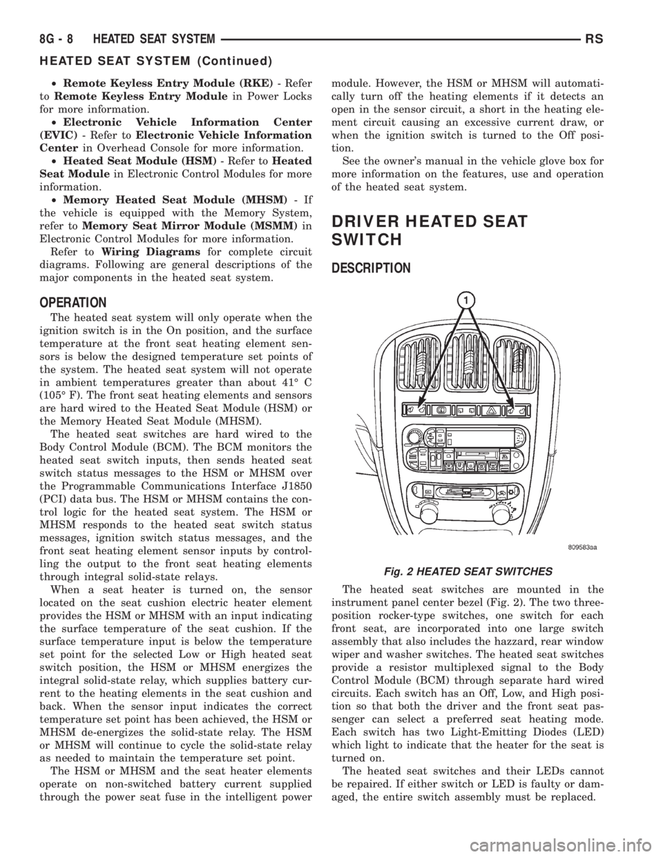
The heated seat switches are mounted in the
instrument panel center bezel (Fig. 2). The two three-
position rocker-type switches, one switch for each
front seat, are incorporated into one large switch
assembly that also includes the hazzard, rear window
wiper and washer switches. The heated seat switches
provide a resistor multiplexed signal to the Body
Control Module (BCM) through separate hard wired
circuits. Each switch has an Off, Low, and High posi-
tion so that both the driver and the front seat pas-
senger can select a preferred seat heating mode.
Each switch has two Light-Emitting Diodes (LED)
which light to indicate that the heater for the seat is
turned on.
The heated seat switches and their LEDs cannot
be repaired. If either switch or LED is faulty or dam-
aged, the entire switch assembly must be replaced.
Fig. 2 HEATED SEAT SWITCHES
8G - 8 HEATED SEAT SYSTEMRS
HEATED SEAT SYSTEM (Continued)
Page 1905 of 4284
OPERATION
There are three positions that can be selected with
each of the heated seat switches: Off, Low, or High.
When the left side of the switch rocker is fully
depressed, the Low position is selected and the high
position LED indicator illuminates. When the right
side of the switch rocker is fully depressed, the High
position is selected and the low position LED indica-
tor illuminates. When the switch rocker is moved to
its neutral position (middle), Off is selected and both
LED indicators are extinguished.
Both switches provide separate resistor multi-
plexed hard wire inputs to the BCM to indicate the
selected switch position. The BCM monitors the
switch inputs and sends heated seat switch status
messages to the Heated Seat Module (HSM) or the
Memory Heated Seat Module (MHSM) over the Pro-
grammable Communications Interface (PCI) data
bus. The HSM or MHSM responds to the heated seat
switch status messages by controlling the output to
the seat heater elements of the selected seat. The
Low heat position set point is about 36É C (97É F),
and the High heat position set point is about 41É C
(105É F).
DIAGNOSIS & TESTING - HEATED SEAT
SWITCH
For complete circuit diagrams, refer toWiring
Diagrams.
WARNING: ON VEHICLES EQUIPPED WITH AIR-
BAGS, REFER TO THE RESTRAINTS SECTION OF
THIS MANUAL BEFORE ATTEMPTING ANY STEER-
ING WHEEL, STEERING COLUMN, SEAT OR
INSTRUMENT PANEL COMPONENT DIAGNOSIS OR
SERVICE. FAILURE TO TAKE THE PROPER PRE-
CAUTIONS COULD RESULT IN ACCIDENTAL AIR-
BAG DEPLOYMENT AND POSSIBLE PERSONAL
INJURY.
(1) Check the fused ignition switch output (run)
fuse in the intelligent power module. If OK, go to
Step 2. If not OK, repair the shorted circuit or com-
ponent as required and replace the faulty fuse.
(2) Turn the ignition switch to the On position.
Check for battery voltage at the fused ignition switch
output (run) fuse in the intelligent power module. If
OK, go to Step 3. If not OK, repair the open fused
ignition switch output (run) circuit to the ignition
switch as required.
(3) Disconnect and isolate the battery negative
cable. Remove the center bezel from the instrument
panel and disconnect the instrument panel wire har-
ness connectors from the heated seat switch connec-
tor receptacle. Check for continuity between the
ground circuit cavity of the instrument panel wireharness connector for the inoperative heated seat
switch(es) and a good ground. There should be conti-
nuity. If OK, go to Step 4. If not OK, repair the open
ground circuit to ground as required.
(4) Reconnect the battery negative cable. Turn the
ignition switch to the On position. Check for battery
voltage at the fused ignition switch output (run) cir-
cuit cavity of the instrument panel wire harness con-
nector for the inoperative heated seat switch(es). If
OK, turn the ignition switch to the Off position, dis-
connect and isolate the battery negative cable, and go
to Step 5. If not OK, repair the open fused ignition
switch output (run) circuit to the intelligent power
module fuse as required.
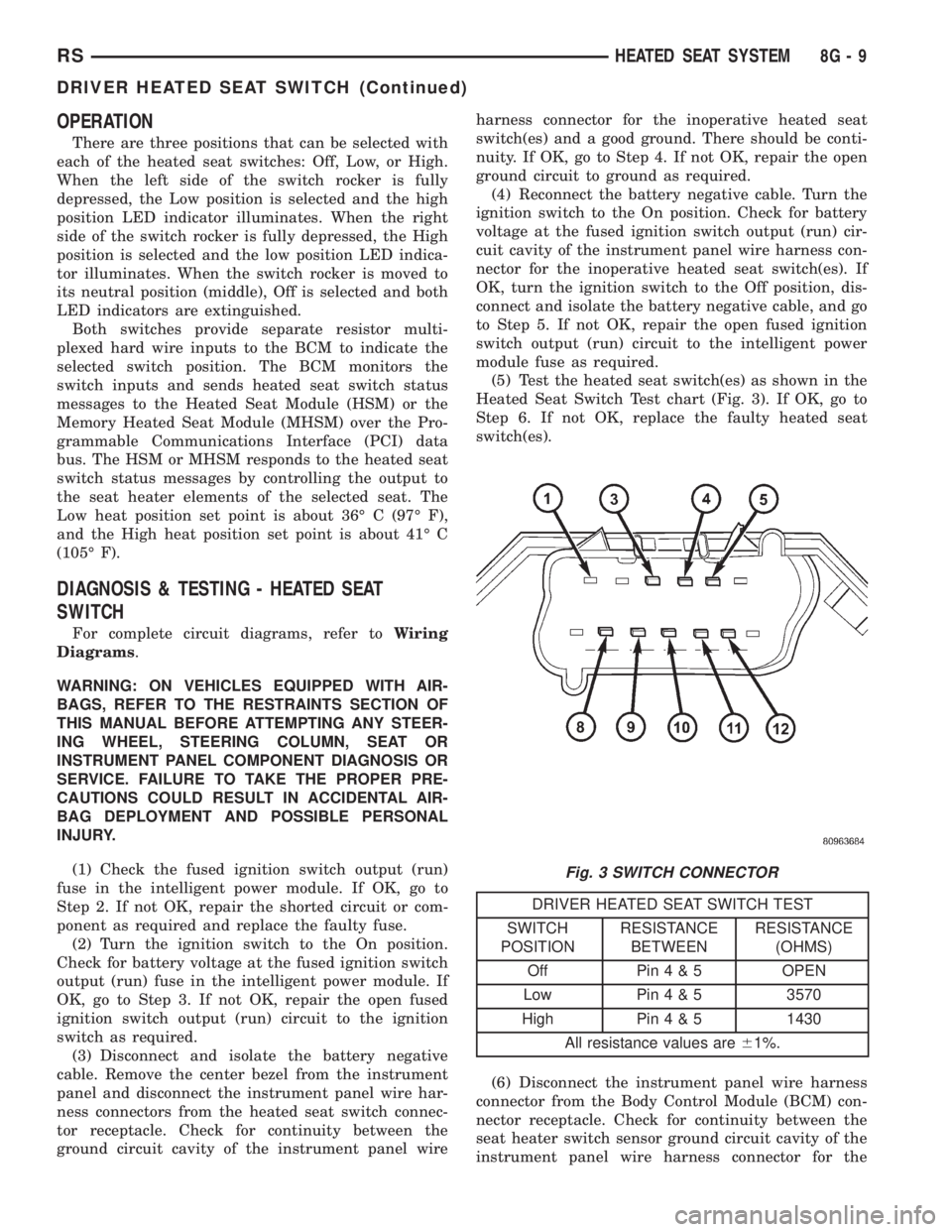
(5) Test the heated seat switch(es) as shown in the
Heated Seat Switch Test chart (Fig. 3). If OK, go to
Step 6. If not OK, replace the faulty heated seat
switch(es).
DRIVER HEATED SEAT SWITCH TEST
SWITCH
POSITIONRESISTANCE
BETWEENRESISTANCE
(OHMS)
Off Pin4&5OPEN
Low Pin4&53570
High Pin4&51430
All resistance values are61%.
(6) Disconnect the instrument panel wire harness
connector from the Body Control Module (BCM) con-
nector receptacle. Check for continuity between the
seat heater switch sensor ground circuit cavity of the
instrument panel wire harness connector for the
Fig. 3 SWITCH CONNECTOR
RSHEATED SEAT SYSTEM8G-9
DRIVER HEATED SEAT SWITCH (Continued)
Page 1908 of 4284
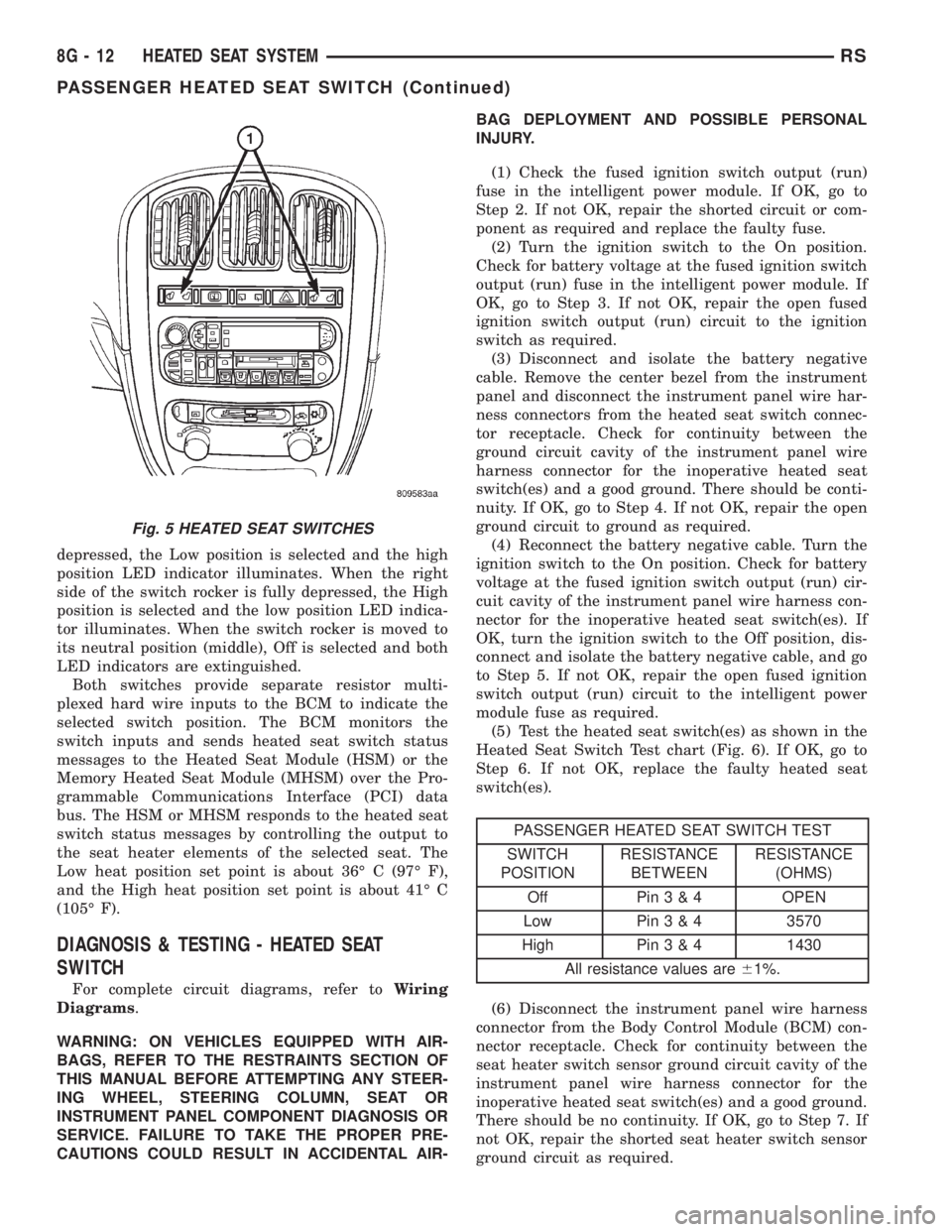
depressed, the Low position is selected and the high
position LED indicator illuminates. When the right
side of the switch rocker is fully depressed, the High
position is selected and the low position LED indica-
tor illuminates. When the switch rocker is moved to
its neutral position (middle), Off is selected and both
LED indicators are extinguished.
Both switches provide separate resistor multi-
plexed hard wire inputs to the BCM to indicate the
selected switch position. The BCM monitors the
switch inputs and sends heated seat switch status
messages to the Heated Seat Module (HSM) or the
Memory Heated Seat Module (MHSM) over the Pro-
grammable Communications Interface (PCI) data
bus. The HSM or MHSM responds to the heated seat
switch status messages by controlling the output to
the seat heater elements of the selected seat. The
Low heat position set point is about 36É C (97É F),
and the High heat position set point is about 41É C
(105É F).
DIAGNOSIS & TESTING - HEATED SEAT
SWITCH
For complete circuit diagrams, refer toWiring
Diagrams.
WARNING: ON VEHICLES EQUIPPED WITH AIR-
BAGS, REFER TO THE RESTRAINTS SECTION OF
THIS MANUAL BEFORE ATTEMPTING ANY STEER-
ING WHEEL, STEERING COLUMN, SEAT OR
INSTRUMENT PANEL COMPONENT DIAGNOSIS OR
SERVICE. FAILURE TO TAKE THE PROPER PRE-
CAUTIONS COULD RESULT IN ACCIDENTAL AIR-BAG DEPLOYMENT AND POSSIBLE PERSONAL
INJURY.
(1) Check the fused ignition switch output (run)
fuse in the intelligent power module. If OK, go to
Step 2. If not OK, repair the shorted circuit or com-
ponent as required and replace the faulty fuse.
(2) Turn the ignition switch to the On position.
Check for battery voltage at the fused ignition switch
output (run) fuse in the intelligent power module. If
OK, go to Step 3. If not OK, repair the open fused
ignition switch output (run) circuit to the ignition
switch as required.
(3) Disconnect and isolate the battery negative
cable. Remove the center bezel from the instrument
panel and disconnect the instrument panel wire har-
ness connectors from the heated seat switch connec-
tor receptacle. Check for continuity between the
ground circuit cavity of the instrument panel wire
harness connector for the inoperative heated seat
switch(es) and a good ground. There should be conti-
nuity. If OK, go to Step 4. If not OK, repair the open
ground circuit to ground as required.
(4) Reconnect the battery negative cable. Turn the
ignition switch to the On position. Check for battery
voltage at the fused ignition switch output (run) cir-
cuit cavity of the instrument panel wire harness con-
nector for the inoperative heated seat switch(es). If
OK, turn the ignition switch to the Off position, dis-
connect and isolate the battery negative cable, and go
to Step 5. If not OK, repair the open fused ignition
switch output (run) circuit to the intelligent power
module fuse as required.
(5) Test the heated seat switch(es) as shown in the
Heated Seat Switch Test chart (Fig. 6). If OK, go to
Step 6. If not OK, replace the faulty heated seat
switch(es).
PASSENGER HEATED SEAT SWITCH TEST
SWITCH
POSITIONRESISTANCE
BETWEENRESISTANCE
(OHMS)
Off Pin3&4OPEN
Low Pin3&43570
High Pin3&41430
All resistance values are61%.
(6) Disconnect the instrument panel wire harness
connector from the Body Control Module (BCM) con-
nector receptacle. Check for continuity between the
seat heater switch sensor ground circuit cavity of the
instrument panel wire harness connector for the
inoperative heated seat switch(es) and a good ground.
There should be no continuity. If OK, go to Step 7. If
not OK, repair the shorted seat heater switch sensor
ground circuit as required.
Fig. 5 HEATED SEAT SWITCHES
8G - 12 HEATED SEAT SYSTEMRS
PASSENGER HEATED SEAT SWITCH (Continued)
Page 1971 of 4284
driving out of a heated garage into winter tempera-
tures.
When the ignition switch is turned to the Off posi-
tion, the last displayed temperature reading stays in
the electronic control modules (CT, CMTC, EVIC)
memory. When the ignition switch is turned to the
On position again, the electronic module will display
the memory temperature for one minute; then update
the display to the current average temperature read-
ing within five minutes.
The thermometer function is supported by an
ambient temperature sensor. The sensor is mounted
outside the passenger compartment near the front
and center of the vehicle, and is hard wired to the
Front Control Module (FCM). The FCM sends tem-
perature status messages to the module over the
J1850 PCI data bus circuit.
Following are general descriptions of the major
components used in the overhead console. Refer to
Wiring Diagrams for complete circuit schematics.
OPERATION
Refer to the vehicle Owner's Manual for specific
operation of each overhead console and its systems.
DIAGNOSIS & TESTING - OVERHEAD
CONSOLE
If the problem with the overhead console is an
inaccurate or scrambled display, refer toSelf-Diag-
nostic Testlater in this group. If the problem with
the overhead console is incorrect Vacuum Fluorescent
Display (VFD) dimming levels, use a DRB IIItscan
tool and the proper Diagnostic Procedures manual to
test for the correct dimming message inputs being
received from the Body Control Module (BCM) or
Front Control Module (FCM) over the J1850 Pro-
grammable Communications Interface (PCI) data bus
circuit. If the problem is a no-display condition, use
the following procedures. For complete circuit dia-
grams, refer toOverhead Consolein the Wiring
Diagrams section of the service manual.
(1) Check the fused B(+) fuse in the intelligent
power module. If OK, go to Step 2. If not OK, repair
the shorted circuit or component as required and
replace the faulty fuse.
(2) Check for battery voltage at the fused B(+) fuse
in the intelligent power module. If OK, go to Step 3.
If not OK, repair the open fused B(+) circuit to the
fused B(+) fuse in the intelligent power module as
required.
(3) Check the fused ignition switch output (run/
start) fuse in the intelligent power module. If OK, go
to Step 4. If not OK, repair the shorted circuit or
component as required and replace the faulty fuse.
(4) Turn the ignition switch to the On position.
Check for battery voltage at the fused ignition switchoutput (run/start) fuse in the intelligent power mod-
ule. If OK, go to Step 5. If not OK, repair the open
fused ignition switch output (run/start) circuit to the
ignition switch as required.
(5) Turn the ignition switch to the Off position.
Disconnect and isolate the battery negative cable.
Remove the overhead console. Check for continuity
between the ground circuit cavity of the roof wire
harness connector for the electronics module and a
good ground. There should be continuity. If OK, go to
Step 6. If not OK, repair the open ground circuit to
ground as required.
(6) Connect the battery negative cable. Check for
battery voltage at the fused B(+) circuit cavity of the
roof wire harness connector for the electronics mod-
ule. If OK, go to Step 7. If not OK, repair the open
fused B(+) circuit to the fused B(+) fuse in the intel-
ligent power module as required.
(7) Turn the ignition switch to the On position.
Check for battery voltage at the fused ignition switch
output (run/start) circuit cavity of the roof wire har-
ness connector for the electronics module. If OK,
refer toSelf-Diagnostic Testlater this group for
further diagnosis of the electronics module and the
J1850 PCI data bus circuit. If not OK, repair the
open fused ignition switch output (run/start) circuit
to the fuse in the intelligent power module as
required.
SELF-DIAGNOSTIC TEST
A self-diagnostic test is used to determine that the
electronics module is operating properly, and that all
the J1850 PCI data bus messages are being received
for initial operation. Initiate the self-diagnostic test
as follows:
(1) With the ignition switch in the Off position, on
Electronic Vehicle Information Center (EVIC) and
Compass Mini-Trip Computer (CMTC) equipped vehi-
cles simultaneously depress and hold theSTEP and
the RESET buttons. On Compass Temperature
Module (CT) equipped vehicles depress theC/T and
the US/M push buttons.
(2) Turn the ignition switch to the On position.
(3) Following completion of these tests, the elec-
tronics module will display one of the following mes-
sages:
²Pass Self Test (EVIC only), PASS (CT,
CMTC)- The electronics module is working properly.
²Failed Self Test (EVIC only), FAIL (CT,
CMTC)- The electronics module has an internal fail-
ure. The electronics module is faulty and must be
replaced.
²Failed J1850 Communication (EVIC only),
BUS (CT, CMTC)- The electronics module is not
receiving proper message input through the J1850
PCI data bus circuit. This can result from one or
RSOVERHEAD CONSOLE8M-3
OVERHEAD CONSOLE (Continued)
Page 2037 of 4284

DIAGNOSIS AND TESTING - POWER SEAT
RECLINER
Following are tests that will help to diagnose the
hard wired components and circuits of the power seat
system. However, if the vehicle is also equipped with
the optional memory system, these tests may not
prove conclusive in the diagnosis of the driver side
power seat. In order to obtain conclusive testing of
the driver side power seat with the memory system
option, the Programmable Communications Interface
(PCI) data bus network and all of the electronic mod-
ules that provide inputs to, or receive outputs from
the memory system components must be checked.The most reliable, efficient, and accurate means to
diagnose the driver side power seat with the memory
system option requires the use of a DRBtscan tool
and the proper Diagnostic Procedures manual. The
DRBtscan tool can provide confirmation that the
PCI data bus is functional, that all of the electronic
modules are sending and receiving the proper mes-
sages on the PCI data bus, and that the memory sys-
tem is receiving the proper hard wired inputs and
relaying the proper hard wired outputs to perform its
driver side power seat functions.
Actuate the power seat recliner switch to move the
power seat recliner adjuster in each direction. The
power seat recliner adjuster should move in both
directions. If the power seat recliner adjuster fails to
operate in only one direction, move the adjuster a
short distance in the opposite direction and test
again to be certain that the adjuster is not at its
travel limit. If the power seat recliner adjuster still
fails to operate in only one direction, refer toPower
Seat Switchin the Diagnosis and Testing section of
this group. If the power recliner adjuster fails to
operate in either direction, perform the following
tests. For complete circuit diagrams, refer toPower
Seatin Wiring Diagrams.
(1) Check the power seat circuit breaker under the
seat. If OK, go to Step 2. If not OK, replace the
faulty power seat circuit breaker.
(2) Check for battery voltage at the power seat cir-
cuit breaker under the seat. If OK, go to Step 3. If
not OK, repair the open fused B(+) circuit to the fuse
in the Intelligent Power Module as required.
(3) Remove the outboard seat cushion side shield
from the seat. Disconnect the seat wire harness con-
nector from the power seat switch connector recepta-
cle. Check for battery voltage at the fused B(+)
circuit cavity of the power seat wire harness connec-
tor for the power seat switch. If OK, go to Step 4. If
not OK, repair the open fused B(+) circuit to the
power seat circuit breaker under the seat as
required.
(4) Check for continuity between the ground cir-
cuit cavity of the power seat wire harness connector
for the power seat switch and a good ground. There
should be continuity. If OK, go to Step 5. If not OK,
repair the open ground circuit to ground as required.
(5) Test the power seat switch. Refer toPower
Seat Switchin the Diagnosis and Testing section of
this group. If the switch tests OK, test the circuits of
the power seat wire harness between the power seat
recliner adjuster motor and the power seat switch for
shorts or opens. If the circuits check OK, replace the
faulty power seat recliner unit. If the circuits are not
OK, repair the power seat wire harness as required.
Fig. 8 Power Seat Recliner and Track - Typical
1 - SEAT BACK FRAME
2 - SEAT CUSHION PAD
3 - POWER RECLINER
4 - SEAT CUSHION FRAME
5 - SHIELD
6 - POWER SEAT TRACK ADJUSTER
RSPOWER SEATS8N-57
RECLINER MOTOR (Continued)