2001 CHRYSLER VOYAGER clock reset
[x] Cancel search: clock resetPage 37 of 4284

this type of system would only refer to this circuit.
A faulty speaker could not cause this DTC.
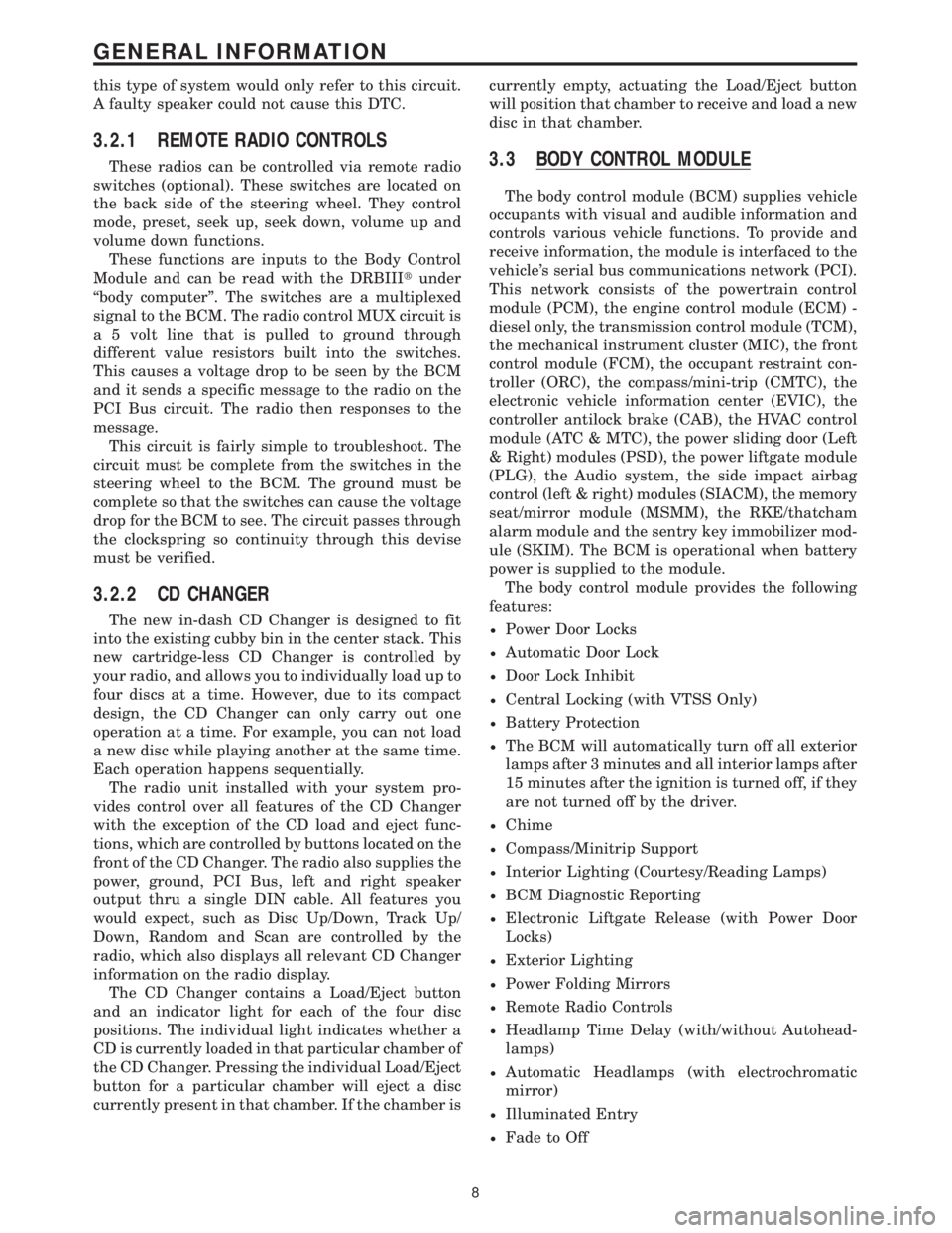
3.2.1 REMOTE RADIO CONTROLS
These radios can be controlled via remote radio
switches (optional). These switches are located on
the back side of the steering wheel. They control
mode, preset, seek up, seek down, volume up and
volume down functions.
These functions are inputs to the Body Control
Module and can be read with the DRBIIItunder
ªbody computerº. The switches are a multiplexed
signal to the BCM. The radio control MUX circuit is
a 5 volt line that is pulled to ground through
different value resistors built into the switches.
This causes a voltage drop to be seen by the BCM
and it sends a specific message to the radio on the
PCI Bus circuit. The radio then responses to the
message.
This circuit is fairly simple to troubleshoot. The
circuit must be complete from the switches in the
steering wheel to the BCM. The ground must be
complete so that the switches can cause the voltage
drop for the BCM to see. The circuit passes through
the clockspring so continuity through this devise
must be verified.
3.2.2 CD CHANGER
The new in-dash CD Changer is designed to fit
into the existing cubby bin in the center stack. This
new cartridge-less CD Changer is controlled by
your radio, and allows you to individually load up to
four discs at a time. However, due to its compact
design, the CD Changer can only carry out one
operation at a time. For example, you can not load
a new disc while playing another at the same time.
Each operation happens sequentially.
The radio unit installed with your system pro-
vides control over all features of the CD Changer
with the exception of the CD load and eject func-
tions, which are controlled by buttons located on the
front of the CD Changer. The radio also supplies the
power, ground, PCI Bus, left and right speaker
output thru a single DIN cable. All features you
would expect, such as Disc Up/Down, Track Up/
Down, Random and Scan are controlled by the
radio, which also displays all relevant CD Changer
information on the radio display.
The CD Changer contains a Load/Eject button
and an indicator light for each of the four disc
positions. The individual light indicates whether a
CD is currently loaded in that particular chamber of
the CD Changer. Pressing the individual Load/Eject
button for a particular chamber will eject a disc
currently present in that chamber. If the chamber iscurrently empty, actuating the Load/Eject button
will position that chamber to receive and load a new
disc in that chamber.
3.3 BODY CONTROL MODULE
The body control module (BCM) supplies vehicle
occupants with visual and audible information and
controls various vehicle functions. To provide and
receive information, the module is interfaced to the
vehicle's serial bus communications network (PCI).
This network consists of the powertrain control
module (PCM), the engine control module (ECM) -
diesel only, the transmission control module (TCM),
the mechanical instrument cluster (MIC), the front
control module (FCM), the occupant restraint con-
troller (ORC), the compass/mini-trip (CMTC), the
electronic vehicle information center (EVIC), the
controller antilock brake (CAB), the HVAC control
module (ATC & MTC), the power sliding door (Left
& Right) modules (PSD), the power liftgate module
(PLG), the Audio system, the side impact airbag
control (left & right) modules (SIACM), the memory
seat/mirror module (MSMM), the RKE/thatcham
alarm module and the sentry key immobilizer mod-
ule (SKIM). The BCM is operational when battery
power is supplied to the module.
The body control module provides the following
features:
²Power Door Locks
²Automatic Door Lock
²Door Lock Inhibit
²Central Locking (with VTSS Only)
²Battery Protection
²The BCM will automatically turn off all exterior
lamps after 3 minutes and all interior lamps after
15 minutes after the ignition is turned off, if they
are not turned off by the driver.
²Chime
²Compass/Minitrip Support
²Interior Lighting (Courtesy/Reading Lamps)
²BCM Diagnostic Reporting
²Electronic Liftgate Release (with Power Door
Locks)
²Exterior Lighting
²Power Folding Mirrors
²Remote Radio Controls
²Headlamp Time Delay (with/without Autohead-
lamps)
²Automatic Headlamps (with electrochromatic
mirror)
²Illuminated Entry
²Fade to Off
8
GENERAL INFORMATION
Page 246 of 4284

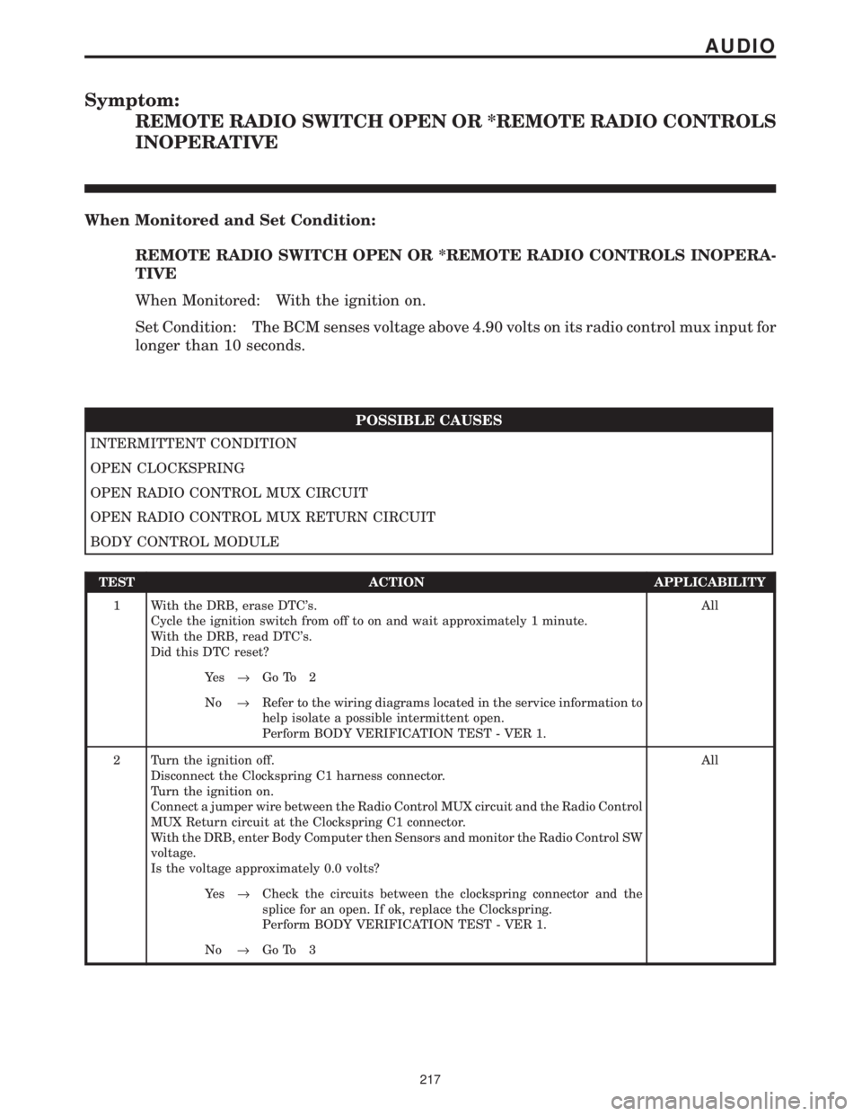
Symptom:
REMOTE RADIO SWITCH OPEN OR *REMOTE RADIO CONTROLS
INOPERATIVE
When Monitored and Set Condition:
REMOTE RADIO SWITCH OPEN OR *REMOTE RADIO CONTROLS INOPERA-
TIVE
When Monitored: With the ignition on.
Set Condition: The BCM senses voltage above 4.90 volts on its radio control mux input for
longer than 10 seconds.
POSSIBLE CAUSES
INTERMITTENT CONDITION
OPEN CLOCKSPRING
OPEN RADIO CONTROL MUX CIRCUIT
OPEN RADIO CONTROL MUX RETURN CIRCUIT
BODY CONTROL MODULE
TEST ACTION APPLICABILITY
1 With the DRB, erase DTC's.
Cycle the ignition switch from off to on and wait approximately 1 minute.
With the DRB, read DTC's.
Did this DTC reset?All
Ye s®Go To 2
No®Refer to the wiring diagrams located in the service information to
help isolate a possible intermittent open.
Perform BODY VERIFICATION TEST - VER 1.
2 Turn the ignition off.
Disconnect the Clockspring C1 harness connector.
Turn the ignition on.
Connect a jumper wire between the Radio Control MUX circuit and the Radio Control
MUX Return circuit at the Clockspring C1 connector.
With the DRB, enter Body Computer then Sensors and monitor the Radio Control SW
voltage.
Is the voltage approximately 0.0 volts?All
Ye s®Check the circuits between the clockspring connector and the
splice for an open. If ok, replace the Clockspring.
Perform BODY VERIFICATION TEST - VER 1.
No®Go To 3
217
AUDIO
Page 248 of 4284

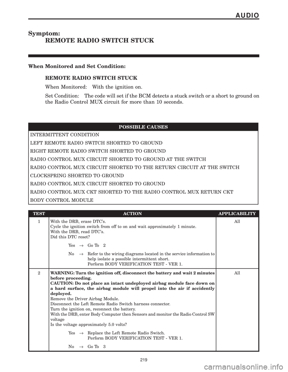
Symptom:
REMOTE RADIO SWITCH STUCK
When Monitored and Set Condition:
REMOTE RADIO SWITCH STUCK
When Monitored: With the ignition on.
Set Condition: The code will set if the BCM detects a stuck switch or a short to ground on
the Radio Control MUX circuit for more than 10 seconds.
POSSIBLE CAUSES
INTERMITTENT CONDITION
LEFT REMOTE RADIO SWITCH SHORTED TO GROUND
RIGHT REMOTE RADIO SWITCH SHORTED TO GROUND
RADIO CONTROL MUX CIRCUIT SHORTED TO GROUND AT THE SWITCH
RADIO CONTROL MUX CIRCUIT SHORTED TO THE RETURN CIRCUIT AT THE SWITCH
CLOCKSPRING SHORTED TO GROUND
RADIO CONTROL MUX CIRCUIT SHORTED TO GROUND
RADIO CONTROL MUX CKT SHORTED TO THE RADIO CONTROL MUX RETURN CKT
BODY CONTROL MODULE
TEST ACTION APPLICABILITY
1 With the DRB, erase DTC's.
Cycle the ignition switch from off to on and wait approximately 1 minute.
With the DRB, read DTC's.
Did this DTC reset?All
Ye s®Go To 2
No®Refer to the wiring diagrams located in the service information to
help isolate a possible intermittent short.
Perform BODY VERIFICATION TEST - VER 1.
2WARNING: Turn the ignition off, disconnect the battery and wait 2 minutes
before proceeding.
CAUTION: Do not place an intact undeployed airbag module face down on
a hard surface, the airbag module will propel into the air if accidently
deployed.
Remove the Driver Airbag Module.
Disconnect the Left Remote Radio Switch harness connector.
Turn the ignition on, reconnect the battery.
With the DRB, enter Body Computer then Sensors and monitor the Radio Control SW
voltage
Is the voltage approximately 5.0 volts?All
Ye s®Replace the Left Remote Radio Switch.
Perform BODY VERIFICATION TEST - VER 1.
No®Go To 3
219
AUDIO
Page 276 of 4284

TEST ACTION APPLICABILITY
2 Turn the ignition off.
Disconnect the ATC Remote Sensor harness connector.
Turn the ignition on.
Measure the voltage of the KDB 2 Data circuit.
Is the voltage above 10.0 volts?All
Ye s®Go To 3
No®Go To 13
3 Turn the ignition off.
Disconnect the ATC Remote Sensor harness connector.
Disconnect the ATC C3 harness connector.
Turn the ignition on.
Measure the voltage of the KDB 2 Data circuit.
Is the voltage above 1.0 volt?All
Ye s®Repair the KDB 2 Data circuit for a short to voltage.
With the DRBIIIt, reset the ATC after repair/replacement is
complete.
Perform BODY VERIFICATION TEST - VER 1.
No®Go To 4
4 Turn the ignition off.
Disconnect the ATC Remote Sensor harness connector.
Use Scope input cable CH7058, Cable to Probe adapter CH7062, and the red and
black test probes.
Connect the scope input cable to the channel one connector on the DRB. Attach the
red and black leads and the cable to probe adapter to the scope input cable.
Select Lab Scope.
Select Live.
Select 12 volt square wave.
Press F2 for Scope.
Press F2 and use the arrows to set the voltage range to 20 volts, the Offset to 4.0, and
the Probe to x10. Press F2 again and set the divisions to 40ms/Div, then press F2
again when complete.
Connect the Black lead to the chassis ground. Connect the Red lead to the KDB 2
Clock circuit in the ATC Remote Sensor harness connector.
Turn the ignition on.
Observe the voltage display on the DRB Lab Scope.
NOTE: The lab scope pattern should look similar to the example given in the
support material and cycle from approximately 0 volts to 8.0 volts.
Did the lab scope pattern and voltage react as noted above?All
Ye s®Go To 5
No®Go To 9
5 Turn the ignition off.
Disconnect the ATC Remote Sensor harness connector.
Measure the resistance between ground and the Sensor Return circuit.
Is the resistance below 10 ohms?All
Ye s®Go To 6
No®Go To 7
247
AUTOMATIC TEMPERATURE CONTROL
FRONT IR SENSOR NOT CALIBRATED (ACTIVE) ÐContinued
Page 277 of 4284

TEST ACTION APPLICABILITY
6 If there are no possible causes remaining, view repair. All
Repair
Replace the ATC Remote Sensor.
With the DRBIIIt, reset the ATC after repair/replacement is
complete.
Perform BODY VERIFICATION TEST - VER 1.
7 Turn the ignition off.
Disconnect the ATC Remote Sensor harness connector.
Measure the resistance of the Sensor Return circuit.
Is the resistance below 5.0 ohms?All
Ye s®Go To 8
No®Repair the Sensor Return circuit for an open.
With the DRBIIIt, reset the ATC after repair/replacement is
complete.
Perform BODY VERIFICATION TEST - VER 1.
8 If there are no possible causes remaining, view repair. All
Repair
Replace the ATC.
With the DRBIIIt, reset the ATC after repair/replacement is
complete.
Perform BODY VERIFICATION TEST - VER 1.
9 Turn the ignition off.
Disconnect the ATC Remote Sensor harness connector.
Disconnect the ATC C3 harness connector.
Turn the ignition on.
Measure the voltage of the KDB 2 Clock circuit.
Is the voltage above 1.0 volt?All
Ye s®Repair the KDB 2 Clock circuit for a short to voltage.
With the DRBIIIt, reset the ATC after repair/replacement is
complete.
Perform BODY VERIFICATION TEST - VER 1.
No®Go To 10
10 Turn the ignition off.
Disconnect the ATC Remote Sensor harness connector.
Disconnect the ATC C3 harness connector.
Measure the resistance between ground and the KDB 2 Clock circuit.
Is the resistance above 100k ohms?All
Ye s®Go To 11
No®Repair the KDB 2 Clock circuit for a short to ground.
With the DRBIIIt, reset the ATC after repair/replacement is
complete.
Perform BODY VERIFICATION TEST - VER 1.
248
AUTOMATIC TEMPERATURE CONTROL
FRONT IR SENSOR NOT CALIBRATED (ACTIVE) ÐContinued
Page 278 of 4284

TEST ACTION APPLICABILITY
11 Turn the ignition off.
Disconnect the ATC Remote Sensor harness connector.
Disconnect the ATC C3 harness connector.
Measure the resistance of the KDB 2 Clock circuit.
Is the resistance below 5.0 ohms?All
Ye s®Go To 12
No®Repair the KDB 2 Clock circuit for an open.
With the DRBIIIt, reset the ATC after repair/replacement is
complete.
Perform BODY VERIFICATION TEST - VER 1.
12 If there are no possible causes remaining, view repair. All
Repair
Replace the ATC.
With the DRBIIIt, reset the ATC after repair/replacement is
complete.
Perform BODY VERIFICATION TEST - VER 1.
13 Turn the ignition off.
Disconnect the ATC Remote Sensor harness connector.
Disconnect the ATC C3 harness connector.
Measure the resistance between ground and the KDB 2 Data circuit.
Is the resistance above 100k ohms?All
Ye s®Go To 14
No®Repair the KDB 2 Data circuit for a short to ground.
With the DRBIIIt, reset the ATC after repair/replacement is
complete.
Perform BODY VERIFICATION TEST - VER 1.
14 Turn the ignition off.
Disconnect the ATC Remote Sensor harness connector.
Disconnect the ATC C3 harness connector.
Measure the resistance of the KDB 2 Data circuit.
Is the resistance below 5.0 ohms?All
Ye s®Go To 15
No®Repair the KDB 2 Data circuit for an open.
With the DRBIIIt, reset the ATC after repair/replacement is
complete.
Perform BODY VERIFICATION TEST - VER 1.
15 If there are no possible causes remaining, view repair. All
Repair
Replace the ATC.
With the DRBIIIt, reset the ATC after repair/replacement is
complete.
Perform BODY VERIFICATION TEST - VER 1.
249
AUTOMATIC TEMPERATURE CONTROL
FRONT IR SENSOR NOT CALIBRATED (ACTIVE) ÐContinued
Page 306 of 4284

TEST ACTION APPLICABILITY
3 Turn the ignition off.
Disconnect the Rear Automatic Temperature Control Switch harness connector.
Disconnect the ATC C2 harness connector.
Turn the ignition on.
Measure the voltage of the KDB Data circuit.
Is the voltage above 1.0 volt?All
Ye s®Repair the KDB Data circuit for a short to voltage.
With the DRBIIIt, reset the ATC after repair/replacement is
complete.
Perform BODY VERIFICATION TEST - VER 1.
No®Go To 4
4 Turn the ignition off.
Disconnect the Rear Automatic Temperature Control Switch harness connector.
Use Scope input cable CH7058, Cable to Probe adapter CH7062, and the red and
black test probes.
Connect the scope input cable to the channel one connector on the DRB. Attach the
red and black leads and the cable to probe adapter to the scope input cable.
Select Lab Scope.
Select Live.
Select 12 volt square wave.
Press F2 for Scope.
Press F2 and use the arrows to set the voltage range to 20 volts, the Offset to 4.0, and
the Probe to x10. Press F2 again and set the divisions to 40ms/Div, then press F2
again when complete.
Connect the Black lead to the chassis ground. Connect the Red lead to the KDB Clock
circuit in the Rear Automatic Temperature Control Switch harness connector.
Turn the ignition on.
Observe the voltage display on the DRB Lab Scope.
NOTE: The lab scope pattern should look similar to the example given in the
support material and cycle from approximately 0 volts to 8.0 volts.
Did the lab scope pattern and voltage react as noted above?All
Ye s®Go To 5
No®Go To 6
5 If there are no possible causes remaining, view repair. All
Repair
Replace the Rear Automatic Temperature Control Switch.
With the DRBIIIt, reset the ATC after repair/replacement is
complete.
Perform BODY VERIFICATION TEST - VER 1.
6 Turn the ignition off.
Disconnect the Rear Automatic Temperature Control Switch harness connector.
Disconnect the ATC C2 harness connector.
Turn the ignition on.
Measure the voltage of the KDB Clock circuit.
Is the voltage above 1.0 volt?All
Ye s®Repair the KDB Clock circuit for a short to voltage.
With the DRBIIIt, reset the ATC after repair/replacement is
complete.
Perform BODY VERIFICATION TEST - VER 1.
No®Go To 7
277
AUTOMATIC TEMPERATURE CONTROL
REAR IR SENSOR NOT CALIBRATED (ACTIVE) ÐContinued
Page 307 of 4284

TEST ACTION APPLICABILITY
7 Turn the ignition off.
Disconnect the Rear Automatic Temperature Control Switch harness connector.
Disconnect the ATC C2 harness connector.
Measure the resistance between ground and the KDB Clock circuit.
Is the resistance above 100k ohms?All
Ye s®Go To 8
No®Repair the KDB Clock circuit for a short to ground.
With the DRBIIIt, reset the ATC after repair/replacement is
complete.
Perform BODY VERIFICATION TEST - VER 1.
8 Turn the ignition off.
Disconnect the Rear Automatic Temperature Control Switch harness connector.
Disconnect the ATC C2 harness connector.
Measure the resistance of the KDB Clock circuit.
Is the resistance below 5.0 ohms?All
Ye s®Go To 9
No®Repair the KDB Clock circuit for an open.
With the DRBIIIt, reset the ATC after repair/replacement is
complete.
Perform BODY VERIFICATION TEST - VER 1.
9 If there are no possible causes remaining, view repair. All
Repair
Replace the ATC.
With the DRBIIIt, reset the ATC after repair/replacement is
complete.
Perform BODY VERIFICATION TEST - VER 1.
10 Turn the ignition off.
Disconnect the Rear Automatic Temperature Control Switch harness connector.
Disconnect the ATC C2 harness connector.
Measure the resistance between ground and the KDB Data circuit.
Is the resistance above 100k ohms?All
Ye s®Go To 11
No®Repair the KDB Data circuit for a short to ground.
With the DRBIIIt, reset the ATC after repair/replacement is
complete.
Perform BODY VERIFICATION TEST - VER 1.
11 Turn the ignition off.
Disconnect the Rear Automatic Temperature Control Switch harness connector.
Disconnect the ATC C2 harness connector.
Measure the resistance of the KDB Data circuit.
Is the resistance below 5.0 ohms?All
Ye s®Go To 12
No®Repair the KDB Data circuit for an open.
With the DRBIIIt, reset the ATC after repair/replacement is
complete.
Perform BODY VERIFICATION TEST - VER 1.
278
AUTOMATIC TEMPERATURE CONTROL
REAR IR SENSOR NOT CALIBRATED (ACTIVE) ÐContinued