2001 CHRYSLER VOYAGER seat memory
[x] Cancel search: seat memoryPage 5 of 4284
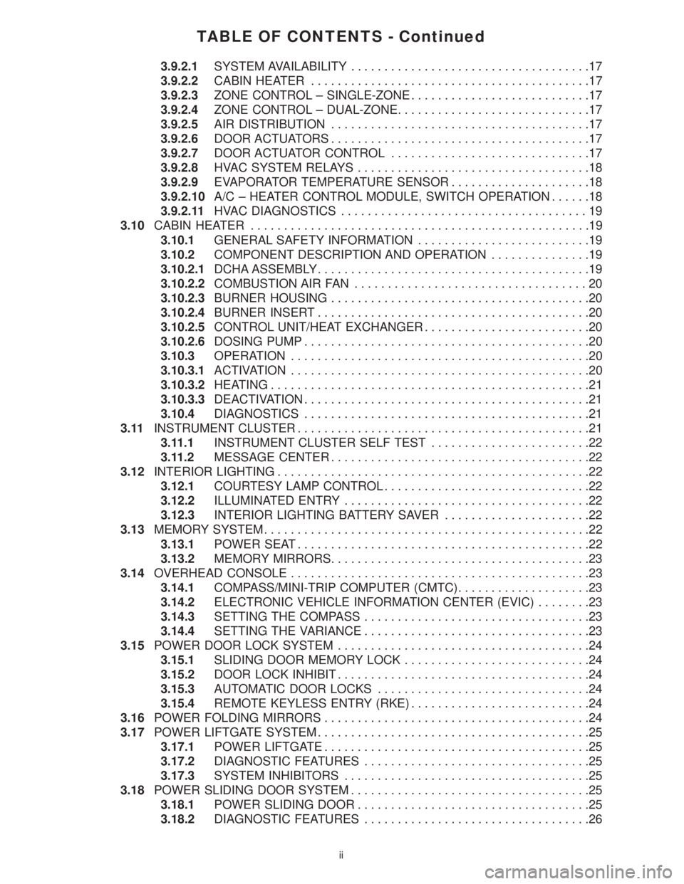
TABLE OF CONTENTS - Continued
3.9.2.1SYSTEM AVAILABILITY....................................17
3.9.2.2CABIN HEATER..........................................17
3.9.2.3ZONE CONTROL ± SINGLE-ZONE...........................17
3.9.2.4ZONE CONTROL ± DUAL-ZONE.............................17
3.9.2.5AIR DISTRIBUTION.......................................17
3.9.2.6DOOR ACTUATORS.......................................17
3.9.2.7DOOR ACTUATOR CONTROL..............................17
3.9.2.8HVAC SYSTEM RELAYS...................................18
3.9.2.9EVAPORATOR TEMPERATURE SENSOR.....................18
3.9.2.10A/C ± HEATER CONTROL MODULE, SWITCH OPERATION......18
3.9.2.11HVAC DIAGNOSTICS.....................................19
3.10CABIN HEATER...................................................19
3.10.1GENERAL SAFETY INFORMATION..........................19
3.10.2COMPONENT DESCRIPTION AND OPERATION...............19
3.10.2.1DCHA ASSEMBLY.........................................19
3.10.2.2COMBUSTION AIR FAN...................................20
3.10.2.3BURNER HOUSING.......................................20
3.10.2.4BURNER INSERT.........................................20
3.10.2.5CONTROL UNIT/HEAT EXCHANGER.........................20
3.10.2.6DOSING PUMP...........................................20
3.10.3OPERATION.............................................20
3.10.3.1ACTIVATION.............................................20
3.10.3.2HEATING................................................21
3.10.3.3DEACTIVATION...........................................21
3.10.4DIAGNOSTICS...........................................21
3.11INSTRUMENT CLUSTER............................................21
3.11.1INSTRUMENT CLUSTER SELF TEST........................22
3.11.2MESSAGE CENTER.......................................22
3.12INTERIOR LIGHTING...............................................22
3.12.1COURTESY LAMP CONTROL...............................22
3.12.2ILLUMINATED ENTRY.....................................22
3.12.3INTERIOR LIGHTING BATTERY SAVER......................22
3.13MEMORY SYSTEM.................................................22
3.13.1POWER SEAT............................................22
3.13.2MEMORY MIRRORS.......................................23
3.14OVERHEAD CONSOLE.............................................23
3.14.1COMPASS/MINI-TRIP COMPUTER (CMTC)....................23
3.14.2ELECTRONIC VEHICLE INFORMATION CENTER (EVIC)........23
3.14.3SETTING THE COMPASS..................................23
3.14.4SETTING THE VARIANCE..................................23
3.15POWER DOOR LOCK SYSTEM......................................24
3.15.1SLIDING DOOR MEMORY LOCK............................24
3.15.2DOOR LOCK INHIBIT......................................24
3.15.3AUTOMATIC DOOR LOCKS................................24
3.15.4REMOTE KEYLESS ENTRY (RKE)...........................24
3.16POWER FOLDING MIRRORS........................................24
3.17POWER LIFTGATE SYSTEM.........................................25
3.17.1POWER LIFTGATE........................................25
3.17.2DIAGNOSTIC FEATURES..................................25
3.17.3SYSTEM INHIBITORS.....................................25
3.18POWER SLIDING DOOR SYSTEM....................................25
3.18.1POWER SLIDING DOOR...................................25
3.18.2DIAGNOSTIC FEATURES..................................26
ii
Page 13 of 4284
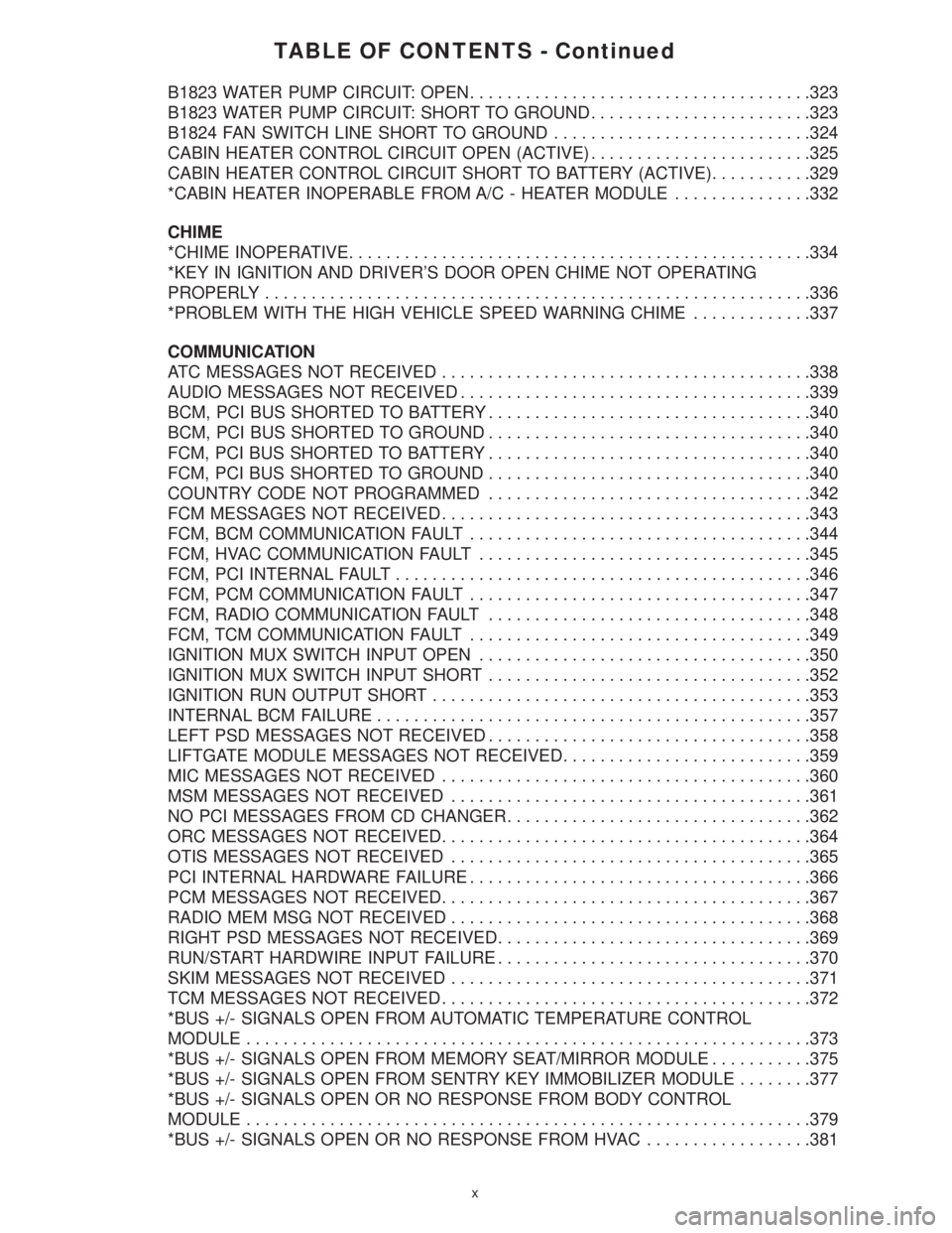
TABLE OF CONTENTS - Continued
B1823 WATER PUMP CIRCUIT: OPEN.....................................323
B1823 WATER PUMP CIRCUIT: SHORT TO GROUND........................323
B1824 FAN SWITCH LINE SHORT TO GROUND............................324
CABIN HEATER CONTROL CIRCUIT OPEN (ACTIVE)........................325
CABIN HEATER CONTROL CIRCUIT SHORT TO BATTERY (ACTIVE)...........329
*CABIN HEATER INOPERABLE FROM A/C - HEATER MODULE...............332
CHIME
*CHIME INOPERATIVE..................................................334
*KEY IN IGNITION AND DRIVER'S DOOR OPEN CHIME NOT OPERATING
PROPERLY...........................................................336
*PROBLEM WITH THE HIGH VEHICLE SPEED WARNING CHIME.............337
COMMUNICATION
ATC MESSAGES NOT RECEIVED........................................338
AUDIO MESSAGES NOT RECEIVED......................................339
BCM, PCI BUS SHORTED TO BATTERY...................................340
BCM, PCI BUS SHORTED TO GROUND...................................340
FCM, PCI BUS SHORTED TO BATTERY...................................340
FCM, PCI BUS SHORTED TO GROUND...................................340
COUNTRY CODE NOT PROGRAMMED...................................342
FCM MESSAGES NOT RECEIVED........................................343
FCM, BCM COMMUNICATION FAULT.....................................344
FCM, HVAC COMMUNICATION FAULT....................................345
FCM, PCI INTERNAL FAULT.............................................346
FCM, PCM COMMUNICATION FAULT.....................................347
FCM, RADIO COMMUNICATION FAULT...................................348
FCM, TCM COMMUNICATION FAULT.....................................349
IGNITION MUX SWITCH INPUT OPEN....................................350
IGNITION MUX SWITCH INPUT SHORT...................................352
IGNITION RUN OUTPUT SHORT.........................................353
INTERNAL BCM FAILURE...............................................357
LEFT PSD MESSAGES NOT RECEIVED...................................358
LIFTGATE MODULE MESSAGES NOT RECEIVED...........................359
MIC MESSAGES NOT RECEIVED........................................360
MSM MESSAGES NOT RECEIVED.......................................361
NO PCI MESSAGES FROM CD CHANGER.................................362
ORC MESSAGES NOT RECEIVED........................................364
OTIS MESSAGES NOT RECEIVED.......................................365
PCI INTERNAL HARDWARE FAILURE.....................................366
PCM MESSAGES NOT RECEIVED........................................367
RADIO MEM MSG NOT RECEIVED.......................................368
RIGHT PSD MESSAGES NOT RECEIVED..................................369
RUN/START HARDWIRE INPUT FAILURE..................................370
SKIM MESSAGES NOT RECEIVED.......................................371
TCM MESSAGES NOT RECEIVED........................................372
*BUS +/- SIGNALS OPEN FROM AUTOMATIC TEMPERATURE CONTROL
MODULE.............................................................373
*BUS +/- SIGNALS OPEN FROM MEMORY SEAT/MIRROR MODULE...........375
*BUS +/- SIGNALS OPEN FROM SENTRY KEY IMMOBILIZER MODULE........377
*BUS +/- SIGNALS OPEN OR NO RESPONSE FROM BODY CONTROL
MODULE.............................................................379
*BUS +/- SIGNALS OPEN OR NO RESPONSE FROM HVAC..................381
x
Page 17 of 4284
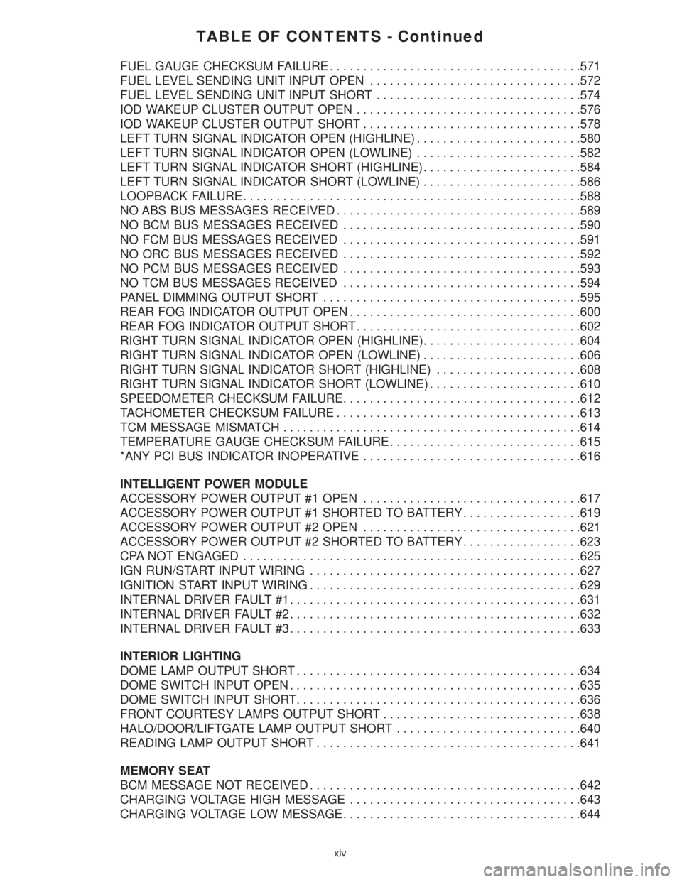
TABLE OF CONTENTS - Continued
FUEL GAUGE CHECKSUM FAILURE......................................571
FUEL LEVEL SENDING UNIT INPUT OPEN................................572
FUEL LEVEL SENDING UNIT INPUT SHORT...............................574
IOD WAKEUP CLUSTER OUTPUT OPEN..................................576
IOD WAKEUP CLUSTER OUTPUT SHORT.................................578
LEFT TURN SIGNAL INDICATOR OPEN (HIGHLINE).........................580
LEFT TURN SIGNAL INDICATOR OPEN (LOWLINE).........................582
LEFT TURN SIGNAL INDICATOR SHORT (HIGHLINE)........................584
LEFT TURN SIGNAL INDICATOR SHORT (LOWLINE)........................586
LOOPBACK FAILURE...................................................588
NO ABS BUS MESSAGES RECEIVED.....................................589
NO BCM BUS MESSAGES RECEIVED....................................590
NO FCM BUS MESSAGES RECEIVED....................................591
NO ORC BUS MESSAGES RECEIVED....................................592
NO PCM BUS MESSAGES RECEIVED....................................593
NO TCM BUS MESSAGES RECEIVED....................................594
PANEL DIMMING OUTPUT SHORT.......................................595
REAR FOG INDICATOR OUTPUT OPEN...................................600
REAR FOG INDICATOR OUTPUT SHORT..................................602
RIGHT TURN SIGNAL INDICATOR OPEN (HIGHLINE)........................604
RIGHT TURN SIGNAL INDICATOR OPEN (LOWLINE)........................606
RIGHT TURN SIGNAL INDICATOR SHORT (HIGHLINE)......................608
RIGHT TURN SIGNAL INDICATOR SHORT (LOWLINE).......................610
SPEEDOMETER CHECKSUM FAILURE....................................612
TACHOMETER CHECKSUM FAILURE.....................................613
TCM MESSAGE MISMATCH.............................................614
TEMPERATURE GAUGE CHECKSUM FAILURE.............................615
*ANY PCI BUS INDICATOR INOPERATIVE.................................616
INTELLIGENT POWER MODULE
ACCESSORY POWER OUTPUT #1 OPEN.................................617
ACCESSORY POWER OUTPUT #1 SHORTED TO BATTERY..................619
ACCESSORY POWER OUTPUT #2 OPEN.................................621
ACCESSORY POWER OUTPUT #2 SHORTED TO BATTERY..................623
CPA NOT ENGAGED...................................................625
IGN RUN/START INPUT WIRING.........................................627
IGNITION START INPUT WIRING.........................................629
INTERNAL DRIVER FAULT #1............................................631
INTERNAL DRIVER FAULT #2............................................632
INTERNAL DRIVER FAULT #3............................................633
INTERIOR LIGHTING
DOME LAMP OUTPUT SHORT...........................................634
DOME SWITCH INPUT OPEN............................................635
DOME SWITCH INPUT SHORT...........................................636
FRONT COURTESY LAMPS OUTPUT SHORT..............................638
HALO/DOOR/LIFTGATE LAMP OUTPUT SHORT............................640
READING LAMP OUTPUT SHORT........................................641
MEMORY SEAT
BCM MESSAGE NOT RECEIVED.........................................642
CHARGING VOLTAGE HIGH MESSAGE...................................643
CHARGING VOLTAGE LOW MESSAGE....................................644
xiv
Page 22 of 4284
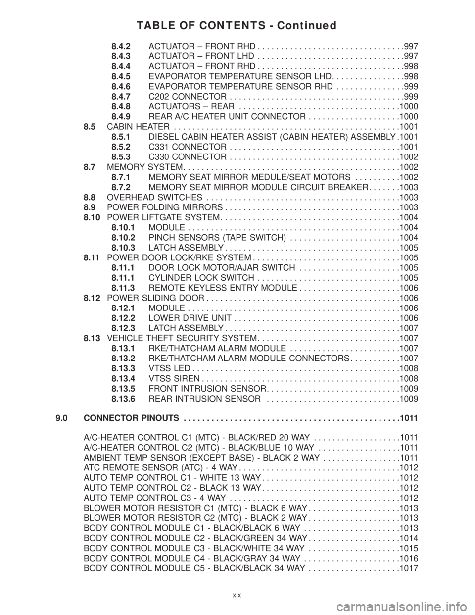
TABLE OF CONTENTS - Continued
8.4.2ACTUATOR ± FRONT RHD................................997
8.4.3ACTUATOR ± FRONT LHD................................997
8.4.4ACTUATOR ± FRONT RHD................................998
8.4.5EVAPORATOR TEMPERATURE SENSOR LHD................998
8.4.6EVAPORATOR TEMPERATURE SENSOR RHD...............999
8.4.7C202 CONNECTOR......................................999
8.4.8ACTUATORS ± REAR...................................1000
8.4.9REAR A/C HEATER UNIT CONNECTOR....................1000
8.5CABIN HEATER.................................................1001
8.5.1DIESEL CABIN HEATER ASSIST (CABIN HEATER) ASSEMBLY .1001
8.5.2C331 CONNECTOR.....................................1001
8.5.3C330 CONNECTOR.....................................1002
8.7MEMORY SYSTEM...............................................1002
8.7.1MEMORY SEAT MIRROR MEDULE/SEAT MOTORS..........1002
8.7.2MEMORY SEAT MIRROR MODULE CIRCUIT BREAKER.......1003
8.8OVERHEAD SWITCHES..........................................1003
8.9POWER FOLDING MIRRORS......................................1003
8.10POWER LIFTGATE SYSTEM.......................................1004
8.10.1MODULE..............................................1004
8.10.2PINCH SENSORS (TAPE SWITCH)........................1004
8.10.3LATCH ASSEMBLY......................................1005
8.11POWER DOOR LOCK/RKE SYSTEM................................1005
8.11.1DOOR LOCK MOTOR/AJAR SWITCH......................1005
8.11.1CYLINDER LOCK SWITCH...............................1005
8.11.3REMOTE KEYLESS ENTRY MODULE......................1006
8.12POWER SLIDING DOOR..........................................1006
8.12.1MODULE..............................................1006
8.12.2LOWER DRIVE UNIT....................................1006
8.12.3LATCH ASSEMBLY......................................1007
8.13VEHICLE THEFT SECURITY SYSTEM...............................1007
8.13.1RKE/THATCHAM ALARM MODULE........................1007
8.13.2RKE/THATCHAM ALARM MODULE CONNECTORS...........1007
8.13.3VTSS LED.............................................1008
8.13.4VTSS SIREN...........................................1008
8.13.5FRONT INTRUSION SENSOR.............................1009
8.13.6REAR INTRUSION SENSOR.............................1009
9.0 CONNECTOR PINOUTS...............................................1011
A/C-HEATER CONTROL C1 (MTC) - BLACK/RED 20 WAY...................1011
A/C-HEATER CONTROL C2 (MTC) - BLACK/BLUE 10 WAY..................1011
AMBIENT TEMP SENSOR (EXCEPT BASE) - BLACK 2 WAY.................1011
ATC REMOTE SENSOR (ATC)-4WAY...................................1012
AUTO TEMP CONTROL C1 - WHITE 13 WAY..............................1012
AUTO TEMP CONTROL C2 - BLACK 13 WAY..............................1012
AUTO TEMP CONTROL C3-4WAY.....................................1012
BLOWER MOTOR RESISTOR C1 (MTC) - BLACK 6 WAY....................1013
BLOWER MOTOR RESISTOR C2 (MTC) - BLACK 2 WAY....................1013
BODY CONTROL MODULE C1 - BLACK/BLACK 6 WAY.....................1013
BODY CONTROL MODULE C2 - BLACK/GREEN 34 WAY....................1014
BODY CONTROL MODULE C3 - BLACK/WHITE 34 WAY....................1015
BODY CONTROL MODULE C4 - BLACK/GRAY 34 WAY.....................1016
BODY CONTROL MODULE C5 - BLACK/BLACK 34 WAY....................1017
xix
Page 23 of 4284
TABLE OF CONTENTS - Continued
C200 - GRAY (BODY SIDE).............................................1018
C200 - GRAY (INSTRUMENT PANEL SIDE)................................1020
C201 - YELLOW (BODY SIDE)..........................................1021
C201 - YELLOW (INSTRUMENT PANEL SIDE).............................1022
C202 - GRAY (COMPONENT SIDE)......................................1022
C202 - GRAY (INSTRUMENT PANEL SIDE)................................1023
C304 - YELLOW (BODY SIDE)..........................................1023
C304 - YELLOW (SEAT SIDE)...........................................1023
C305 - GRAY (BODY SIDE).............................................1024
C306 - YELLOW (BODY SIDE)..........................................1024
C306 - YELLOW (SEAT SIDE)...........................................1024
C307 - GRAY (BODY SIDE).............................................1024
C307 - GRAY (SEAT SIDE).............................................1025
C311 - GRAY (BODY SIDE).............................................1025
C311 - GRAY (REAR A/C JUMPER SIDE).................................1026
C314 (HIGH LINE) - BLACK (BODY SIDE).................................1026
C314 (HIGH LINE) - BLACK (LIFTGATE SIDE).............................1027
C315 (HIGH LINE) - BLACK (BODY SIDE).................................1027
C315 (HIGH LINE) - BLACK (LIFTGATE SIDE).............................1027
C316 (POWER SLIDING DOOR) - BLACK (LEFT DOOR WIRE TRACK ASSEMBLY
SIDE)...............................................................1028
C316 (POWER SLIDING DOOR) - BLACK (LEFT SLIDING DOOR SIDE)........1028
C317 (POWER SLIDING DOOR) - BLACK (RIGHT DOOR WIRE TRACK ASSEMBLY
SIDE)...............................................................1028
C317 (POWER SLIDING DOOR) - BLACK (RIGHT SLIDING DOOR SIDE)......1028
C322 (MEMORY) - BLACK (BODY SIDE)..................................1029
C322 (MEMORY) - BLACK (POWER SEAT SIDE)...........................1029
C324 (MANUAL SLIDING DOOR) - BLACK (LEFT DOOR WIRE TRACK ASSEMBLY
SIDE................................................................1029
C324 (MANUAL SLIDING DOOR) - BLACK (LEFT MANUAL SLIDING DOOR
SIDE)...............................................................1030
C325 (MANUAL SLIDING DOOR) - BLACK (RIGHT DOOR WIRE TRACK ASSEMBLY
SID.................................................................1030
C325 (MANUAL SLIDING DOOR) - BLACK (RIGHT MANUAL SLIDING DOOR
SIDE)...............................................................1030
C326 - YELLOW (SAFETY SEAT SIDE)...................................1030
C326 - YELLOW (SEAT SIDE)...........................................1030
C327 - YELLOW (SAFETY SEAT SIDE)...................................1031
C327 - YELLOW (SEAT SIDE)...........................................1031
C330 (DIESEL) - GRAY (CABIN HEATER JUMPER SIDE)....................1031
C330 (DIESEL) - LT. GRAY (BODY SIDE)..................................1031
C331 (DIESEL) - BLACK (CABIN HEATER JUMPER SIDE)...................1031
C331 (DIESEL) - GRAY (CABIN HEATED COMPONENT SIDE)................1032
CABIN HEATER ASSIST C1 (DIESEL) - BLACK 6 WAY......................1032
CABIN HEATER ASSIST C2 (DIESEL) - BLACK 2 WAY......................1032
CD CHANGER-8WAY................................................1033
CENTER DOME LAMP (BASE/HIGH LINE) - GRAY 3 WAY...................1033
CLOCKSPRING C1 - WHITE 6 WAY......................................1033
CLOCKSPRING C2 - YELLOW 4 WAY....................................1034
CLOCKSPRING C4 - BLACK 2 WAY......................................1034
CLOCKSPRING C5 - YELLOW 4 WAY....................................1034
CONTROLLER ANTILOCK BRAKE - BLACK 24 WAY........................1035
DATA LINK CONNECTOR - BLACK 16 WAY...............................1035
xx
Page 25 of 4284
TABLE OF CONTENTS - Continued
LEFT REMOTE RADIO SWITCH - BLACK 2 WAY...........................1053
LEFT SEAT AIRBAG - YELLOW 2 WAY...................................1053
LEFT SIDE IMPACT AIRBAG CONTROL MODULE - YELLOW/RED 7 WAY......1053
LEFT SLIDING DOOR CONTROL MODULE C1 (POWER SLIDING DOOR) -
BLACK 8 WAY........................................................1053
LEFT SLIDING DOOR CONTROL MODULE C2 (POWER SLIDING DOOR) -
BLACK/RED 20 WAY..................................................1054
LEFT SLIDING DOOR LATCH SENSING SWITCH (POWER SLIDING DOOR) -
BLACK 6 WAY........................................................1054
LEFT SLIDING DOOR LOCK MOTOR (POWER SLIDING DOOR) - BLACK 4
WAY................................................................1054
LEFT SLIDING DOOR LOCK MOTOR/AJAR SWITCH (MANUAL
SLIDING DOOR) - BLACK 4 WAY........................................1055
LEFT SLIDING DOOR MOTOR (POWER SLIDING DOOR) - BLACK 8 WAY.....1055
LEFT STOP/TURN SIGNAL RELAY (TRAILER TOW) - BLACK 5 WAY..........1055
LEFT VISOR/VANITY LAMP (PREMIUM/LUXURY) - BLACK 2 WAY............1055
LICENSE LAMP (POWER LIFTGATE) - DK. GRAY 8 WAY....................1056
LICENSE LAMP (POWER RELEASE) - DK. GRAY 4 WAY....................1056
LIFTGATE AJAR SWITCH (MANUAL RELEASE) - BLACK 2 WAY..............1056
LIFTGATE AJAR SWITCH (POWER RELEASE) - BLACK 4 WAY..............1056
LIFTGATE CINCH/RELEASE MOTOR (POWER LIFTGATE) - BLUE 7 WAY......1057
LIFTGATE CYLINDER LOCK SWITCH - BLACK 2 WAY......................1057
LIFTGATE LEFT PINCH SENSOR (POWER LIFTGATE) - BLACK 2 WAY........1057
LIFTGATE RIGHT PINCH SENSOR (POWER LIFTGATE) - BLACK 2 WAY......1057
MEMORY POWER SEAT SWITCH - GREEN 10 WAY........................1058
MEMORY SEAT FRONT VERTICAL MOTOR - RED 2 WAY...................1058
MEMORY SEAT FRONT VERTICAL POSITION SENSOR - BLACK 3 WAY......1058
MEMORY SEAT HORIZONTAL MOTOR - BLACK 2 WAY.....................1058
MEMORY SEAT HORIZONTAL POSITION SENSOR - BLACK 3 WAY...........1058
MEMORY SEAT REAR VERTICAL MOTOR - RED 2 WAY....................1059
MEMORY SEAT REAR VERTICAL POSITION SENSOR - BLACK 3 WAY........1059
MEMORY SEAT RECLINER MOTOR - GREEN 2 WAY.......................1059
MEMORY SEAT RECLINER POSITION SENSOR - BLACK 3 WAY.............1059
MEMORY SEAT SWITCH - BLACK 2 WAY.................................1059
MEMORY SEAT/MIRROR MODULE C1 - GRAY 2 WAY......................1060
MEMORY SEAT/MIRROR MODULE C2 - GRAY 26 WAY.....................1060
MEMORY SEAT/MIRROR MODULE C3 - GRAY 16 WAY.....................1060
MEMORY SEAT/MIRROR MODULE C4 - WHITE 12 WAY....................1061
MODE DOOR ACTUATOR (ATC) - GRAY 2 WAY...........................1061
MODE DOOR ACTUATOR (MTC) - GRAY 2 WAY...........................1061
MULTI-FUNCTION SWITCH - BLACK 4 WAY...............................1061
OCCUPANT RESTRAINT CONTROLLER - YELLOW/RED 23 WAY.............1062
OVERHEAD CONSOLE (EXCEPT BASE) - BLACK 12 WAY..................1062
PASSENGER AIRBAG - YELLOW 4 WAY..................................1063
PASSENGER BLEND DOOR ACTUATOR (ATC) - GRAY 2 WAY...............1063
PASSENGER BLEND DOOR ACTUATOR (MTC) - GRAY 2 WAY...............1063
PASSENGER DOOR LOCK SWITCH - BLACK 3 WAY.......................1063
PASSENGER FOLDING MIRROR RELAY (BUILT-UP-EXPORT) - BLUE 9 WAY . .1064
PASSENGER SEAT BELT SWITCH-2WAY...............................1064
PASSENGER SEAT BELT TENSIONER-2WAY............................1064
FUSES (IPM).........................................................1066
ACCESSORY RELAY..................................................1066
DEFOGGER RELAY...................................................1066
xxii
Page 30 of 4284
1.0 INTRODUCTION
The procedures contained in this manual include
all the specifications, instructions and graphics
needed to diagnose 2001 body system problems. The
diagnostics in this manual are based on the failure
condition or symptom being present at the time of
diagnosis.
Please follow the recommendations below when
choosing your diagnostic path.
1. First make sure the DRBIIItis communicating
with the appropriate modules; i.e., if the
DRBIIItdisplays a ªNo Responseº or a ªBus6
Signals Openº condition, you must diagnose that
first.
2. Read DTC's (diagnostic trouble codes) with the
DRBIIIt.
3. If no DTC's are present, identify the customer
complaint.
4. Once the DTC or customer complaint is identi-
fied, locate the matching test in the Table of
Contents and begin to diagnose the symptom.
All component location views are in Section 8.0. All
connector pinouts are in Section 9.0. All schematics
are in Section 10.0. All Charts and Graphs are in
Section 11.0.
An * placed before the symptom description indi-
cated a customer complaint.
When repairs are required, refer to the appropri-
ate service information for the proper removal and
repair procedure.
Diagnostic procedures change every year. New
diagnostic systems may be added: carryover systems
may be enhanced. READ THIS MANUAL BEFORE
TRYING TO DIAGNOSE A VEHICLE DIAGNOS-
TIC TROUBLE CODE. It is recommended that you
review the entire manual to become familiar with all
the new and changed diagnostic procedures.
This book reflects many suggested changes from
readers of past issues. After using this book, if you
have any comments or suggestions, please fill out
the form in the back of this book and mail it back to
us.
1.1 SYSTEM COVERAGE
This diagnostic procedures manual covers all
2001 Chrysler Voyager and Caravan vehicles. This
diagnostic procedures manual also covers both left
hand drive (LHD) and right hand drive (RHD)
vehicles. There may be some slight differences in
the location views of components. If the location
views shown are on a LHD vehicle, a RHD vehicle
will be symmetrically opposite.
1.2 SIX-STEP TROUBLESHOOTING
PROCEDURE
Diagnosis of the body system is done in six basic
steps:
²verification of complaint
²verification of any related symptoms
²symptom analysis
²problem isolation
²repair of isolated problem
²verification of proper operation
2.0 IDENTIFICATION OF
SYSTEM
The vehicle systems that are part of the ªbodyº
system are:
²Airbag
²Audio
²Cabin Heater
²Chime
²Communication
²Door Ajar System
²Electrically heated system
²Exterior lighting
²Heating and A/C
²Instrument Cluster
²Interior Lighting
²Manual Temperature Control
²Memory Seat
²Overhead Console
²Power Door Lock/RKE
²Power Folding Mirrors
²Power Sliding Doors
²Power Liftgate
²Power windows
²Vehicle Theft Security System (VTSS)
²Windshield Wiper and Washer
3.0 SYSTEM DESCRIPTION AND
FUNCTIONAL OPERATION
The body system on the 2001 RG consists of a
combination of modules that communicate over the
PCI bus (Programmable Communication Interface
multiplex system). Through the PCI bus, informa-
tion about the operation of vehicle components and
circuits is relayed quickly to the appropriate mod-
ule(s). All modules receive all the information trans-
1
GENERAL INFORMATION
Page 37 of 4284
this type of system would only refer to this circuit.
A faulty speaker could not cause this DTC.
3.2.1 REMOTE RADIO CONTROLS
These radios can be controlled via remote radio
switches (optional). These switches are located on
the back side of the steering wheel. They control
mode, preset, seek up, seek down, volume up and
volume down functions.
These functions are inputs to the Body Control
Module and can be read with the DRBIIItunder
ªbody computerº. The switches are a multiplexed
signal to the BCM. The radio control MUX circuit is
a 5 volt line that is pulled to ground through
different value resistors built into the switches.
This causes a voltage drop to be seen by the BCM
and it sends a specific message to the radio on the
PCI Bus circuit. The radio then responses to the
message.
This circuit is fairly simple to troubleshoot. The
circuit must be complete from the switches in the
steering wheel to the BCM. The ground must be
complete so that the switches can cause the voltage
drop for the BCM to see. The circuit passes through
the clockspring so continuity through this devise
must be verified.
3.2.2 CD CHANGER
The new in-dash CD Changer is designed to fit
into the existing cubby bin in the center stack. This
new cartridge-less CD Changer is controlled by
your radio, and allows you to individually load up to
four discs at a time. However, due to its compact
design, the CD Changer can only carry out one
operation at a time. For example, you can not load
a new disc while playing another at the same time.
Each operation happens sequentially.
The radio unit installed with your system pro-
vides control over all features of the CD Changer
with the exception of the CD load and eject func-
tions, which are controlled by buttons located on the
front of the CD Changer. The radio also supplies the
power, ground, PCI Bus, left and right speaker
output thru a single DIN cable. All features you
would expect, such as Disc Up/Down, Track Up/
Down, Random and Scan are controlled by the
radio, which also displays all relevant CD Changer
information on the radio display.
The CD Changer contains a Load/Eject button
and an indicator light for each of the four disc
positions. The individual light indicates whether a
CD is currently loaded in that particular chamber of
the CD Changer. Pressing the individual Load/Eject
button for a particular chamber will eject a disc
currently present in that chamber. If the chamber iscurrently empty, actuating the Load/Eject button
will position that chamber to receive and load a new
disc in that chamber.
3.3 BODY CONTROL MODULE
The body control module (BCM) supplies vehicle
occupants with visual and audible information and
controls various vehicle functions. To provide and
receive information, the module is interfaced to the
vehicle's serial bus communications network (PCI).
This network consists of the powertrain control
module (PCM), the engine control module (ECM) -
diesel only, the transmission control module (TCM),
the mechanical instrument cluster (MIC), the front
control module (FCM), the occupant restraint con-
troller (ORC), the compass/mini-trip (CMTC), the
electronic vehicle information center (EVIC), the
controller antilock brake (CAB), the HVAC control
module (ATC & MTC), the power sliding door (Left
& Right) modules (PSD), the power liftgate module
(PLG), the Audio system, the side impact airbag
control (left & right) modules (SIACM), the memory
seat/mirror module (MSMM), the RKE/thatcham
alarm module and the sentry key immobilizer mod-
ule (SKIM). The BCM is operational when battery
power is supplied to the module.
The body control module provides the following
features:
²Power Door Locks
²Automatic Door Lock
²Door Lock Inhibit
²Central Locking (with VTSS Only)
²Battery Protection
²The BCM will automatically turn off all exterior
lamps after 3 minutes and all interior lamps after
15 minutes after the ignition is turned off, if they
are not turned off by the driver.
²Chime
²Compass/Minitrip Support
²Interior Lighting (Courtesy/Reading Lamps)
²BCM Diagnostic Reporting
²Electronic Liftgate Release (with Power Door
Locks)
²Exterior Lighting
²Power Folding Mirrors
²Remote Radio Controls
²Headlamp Time Delay (with/without Autohead-
lamps)
²Automatic Headlamps (with electrochromatic
mirror)
²Illuminated Entry
²Fade to Off
8
GENERAL INFORMATION