2001 CHRYSLER VOYAGER seat memory
[x] Cancel search: seat memoryPage 40 of 4284
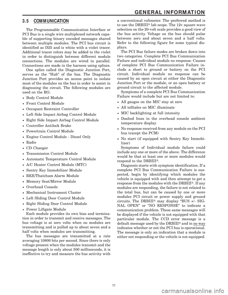
3.5 COMMUNICATION
The Programmable Communication Interface or
PCI Bus is a single wire multiplexed network capa-
ble of supporting binary encoded messages shared
between multiple modules. The PCI bus circuit is
identified as D25 and is white with a violet tracer.
Additional tracer colors may be added to the violet
in order to distinguish between different module
connections. The modules are wired in parallel.
Connections are made in the harness using splices.
One splice called the Diagnostic Junction Port,
serves as the ªHubº of the bus. The Diagnostic
Junction Port provides an access point to isolate
most of the modules on the bus in order to assist in
diagnosing the circuit. The following modules are
used on the RG:
²Body Control Module
²Front Control Module
²Occupant Restraint Controller
²Left Side Impact Airbag Control Module
²Right Side Impact Airbag Control Module
²Controller Antilock Brake
²Powertrain Control Module
²Engine Control Module - Diesel Only
²Radio
²CD Changer
²Transmission Control Module
²Automatic Temperature Control Module
²A/C Heater Control Module (MTC)
²Sentry Key Immobilizer Module
²RKE/Thatcham Alarm Module
²Memory Seat/Mirror Module
²Overhead Console
²Mechanical Instrument Cluster
²Left Sliding Door Control Module
²Right Sliding Door Control Module
²Power Liftgate Module
Each module provides its own bias and termina-
tion in order to transmit and receive messages. The
bus voltage is at zero volts when no modules are
transmitting and is pulled up to about seven and a
half volts when modules are transmitting.
The bus messages are transmitted at a rate
averaging 10800 bits per second. Since there is only
voltage present when the modules transmit and the
message length is only about 500 milliseconds, it is
ineffective to try and measure the bus activity witha conventional voltmeter. The preferred method is
to use the DRBIIItlab scope. The 12v square wave
selection on the 20-volt scale provides a good view of
the bus activity. Voltage on the bus should pulse
between zero and about seven and a half volts.
Refer to the following figure for some typical dis-
plays.
The PCI Bus failure modes are broken down into
two categories. Complete PCI Bus Communication
Failure and individual module no response. Causes
of complete PCI Bus Communication Failure in-
clude a short to ground or battery on the PCI
circuit. Individual module no response can be
caused by an open circuit at either the Diagnostic
Junction Port or the module, or an open battery or
ground circuit to the affected module.
Symptoms of a complete PCI Bus Communication
Failure would include but are not limited to:
²All gauges on the MIC stay at zero
²All telltales on MIC illuminate
²MIC backlighting at full intensity
²Dashed lines in the overhead console ambient
temperature display
²No response received from any module on the PCI
bus (except the PCM)
²No start (if equipped with Sentry Key Immobi-
lizer)
Symptoms of Individual module failure could
include any one or more of the above. The difference
would be that at least one or more modules would
respond to the DRBIIIt.
Diagnosis starts with symptom identification. If a
complete PCI Bus Communication Failure is sus-
pected, begin by identifying which modules the
vehicle is equipped with and then attempt to get a
response from the modules with the DRBIIIt.Ifany
modules are responding, the failure is not related to
the total bus, but can be caused by one or more
modules PCI circuit or power supply and ground
circuits. The DRBIIItmay display ªBUS +/- SIG-
NAL OPENº or ªNO RESPONSEº to indicate a
communication problem. These same messages will
be displayed if the vehicle is not equipped with that
particular module. The CCD error message is a
default message used by the DRBIIItand in no way
indicates whether or not the PCI bus is operational.
The message is only an indication that a module is
either not responding or the vehicle is not equipped.
11
GENERAL INFORMATION
Page 51 of 4284

On vehicles equipped with AutoStick, the display
includes an O/D OFF indicator that is illuminated
when the driver presses the Overdrive Off button
on the transaxle shifter.
3.11.1 INSTRUMENT CLUSTER SELF TEST
1. Depress and hold the Odometer Reset button.
2. Turn the ignition switch to the RUN/START
position.
3. Release the Odometer reset button.
The Instrument Cluster will illuminate all indi-
cators and step the gauges through several calibra-
tion points. Also, the odometer will display any
stored codes that may have set.
3.11.2 MESSAGE CENTER
The Message Center is located above the brow of
the Instrument Cluster. It houses the following
warning indicators: Check Engine/Service Engine
Soon, high beam, left and right turn signals, Secu-
rity Alarm Set, and low oil pressure. On base
models equipped with the three-speed transaxle,
these indicators appear in the face of the cluster.
The Security Alarm set indicator is a red circle.
Activation of Instrument Cluster indicators is
coordinated with indicators in the message center
and EVIC to avoid redundancy. A revised safety
standard now requires that the seat belt warning
lamp in the Instrument Cluster remain lit if the
driver seat belt is not buckled. A headlamp out ISO
indicator has been added to the Instrument Cluster
to alert the driver when a headlamp is not function-
ing.
3.12 INTERIOR LIGHTING
3.12.1 COURTESY LAMP CONTROL
The body controller has direct control over all of
the vehicle's courtesy lamps. The body computer
will illuminate the courtesy lamps under any of the
following conditions:
1. Any door ajar and courtesy lamp switch on the
headlamp switch is not in the dome off position.
2. The courtesy lamp switch on the headlamp
switch is in the dome on position.
3. A Remote Keyless Entry unlock message is re-
ceived.
4. Driver door unlocked with key (with VTSS only).
3.12.2 ILLUMINATED ENTRY
Illuminated entry will be initiated when the cus-
tomer enters the vehicle by unlocking the doors
with the key fob, or with the key if the vehicle is
equipped with vehicle theft alarm. Upon exiting thevehicle, if the lock button is pressed with a door
open, illuminated entry will cancel when the door
closes. If the doors are closed and the ignition
switch is turned on, the illuminated entry also
cancels. The illuminated entry feature will not
operate if the courtesy lamp switch is in the dome
off position.
3.12.3 INTERIOR LIGHTING BATTERY
SAVER
If any of the interior lamps are left on after the
ignition is turned off, the BCM will turn them off
after 8 minutes. To return to normal operation, the
courtesy lamps will operate after the dome lamp
switch or door ajar switch changes state. The glove
box and switched reading lamps require that the
ignition be turned to the on/acc position.
3.13 MEMORY SYSTEM
The memory system consists of power driver 's
seat, power mirrors and radio presets. The Memory
Seat/Mirror Module (MSMM) is located under the
driver 's seat. It receives input from the following:
driver 's manual 8-way seat switch, driver 's seat
position sensors, PCI bus circuits, and the power
mirror sensors. The module uses these inputs to
perform the following functions: position the driv-
er 's memory seat, both exterior mirrors (during
recalls), and send/receive the memory system infor-
mation over the PCI bus.
The Memory Set Switch is wired to the Body
Control Module (BCM). When a button (either #1 or
#2) is pressed on the set switch causes the to BCM
send a message to the MSMM which in turn sends
a motion status messages to the BCM. If the BCM
receives no motion from the MSMM it will send a
recall message to the MSMM and radio (once igni-
tion is in run or accessory). The MSMM will in turn
position the drivers seat, both mirrors along with
recalling the radio presets. If the drivers seat or
either exterior mirror is inoperative from its own
respective switches, use the service information
and schematic to diagnose the problem. This man-
ual addresses the memory problems only and it is
assumed there is not a basic component failure.
3.13.1 POWER SEAT
The memory power seat provides the driver with
2 position settings for the driver 's seat. Each power
seat motor is connected to the MSMM with two
motor drive circuits. Each circuit is switched be-
tween battery and ground. By being able to bi-
directionally drive the circuits, the MSMM controls
the movement of the motors based on input from
the power seat switch or from the position sensors
when performing a memory recall. Each motor
22
GENERAL INFORMATION
Page 52 of 4284
contains a potentiometer to monitor the seat posi-
tion. To monitor the position of the motor, the
MSMM sends out a 5-volt reference on the sensor
supply circuit. The sensor is grounded back to the
module on a common ground circuit. Based on the
position of the sensor, the MSMM monitors the
voltage change through the sensor on a separate
signal circuit.
The MSMM stores the input value of each of the
four seat potentiometers in memory when the sys-
tem requests a set. The driver can initiate a mem-
ory recall, using either the door mounted memory
switch or the RKE transmitter (if the remote linked
to memory feature is enabled via the EVIC). When
initiated, the MSMM adjusts the four seat sensors
(by using the motors) to match the memorized seat
position data.
For safety, the memory seat recall is disabled by
the MSMM when the vehicle is out of park position
or if the speed is not zero. Any obstruction to seat
movement over a 2-second delay will cause the seat
to stop moving in which case a stalled motor would
be detected by the MSMM and the corresponding
seat output would be deactivated. However, if the
object obstructing the seat is removed, the seat will
function normally again.
3.13.2 MEMORY MIRRORS
Each outside mirror contains vertical and hori-
zontal bi-directional drive positioning motors and
position sensors. The MSMM provides a 5-volt
reference on the signal circuit to each position
sensor. The sensors share a common ground circuit.
The MSMM monitors the position of the mirror
motors by measuring the voltage on each signal
circuit. When a memory position is set, the MSMM
monitors and stores the position of the outside
mirrors. The MSMM adjusts the mirrors to the
appropriate positions when a memory recall mes-
sage is received from the RKE or is requested from
the memory set switch.
The power mirror switch during non-memory
operation operates both mirrors independently of
the MSMM.
3.14 OVERHEAD CONSOLE
3.14.1 COMPASS/MINI-TRIP COMPUTER
(CMTC)
The compass/mini-trip computer is located in the
overhead console. It displays to the driver the
direction the vehicle is traveling and the current
outside temperature, as well as the following trav-
eler navigational information: average fuel econ-
omy (AVG ECO), distance to empty (DTE), instan-
taneous fuel economy (ECO), elapsed time (ET),and trip odometer (ODO). The information needed
for the CMTC functions is received over the PCI bus
from other modules.
3.14.2 ELECTRONIC VEHICLE
INFORMATION CENTER (EVIC)
The Electronic Vehicle Information Center
(EVIC) includes all the same functions and is lo-
cated in the same area as the Compass/Mini-Trip
Computer, but it adds a number of warning mes-
sages. Also, the EVIC messages are spelled out on
the screen, for example, DISTANCE TO EMPTY,
where the Mini-Trip Computer displays only shows
DTE.
If the compass/mini-trip computer or EVIC has
been replaced, it may be necessary to reset the
calibration.
3.14.3 SETTING THE COMPASS
The compass/mini-trip computer and EVIC are
self-calibrated and requires no adjustment. The
word CAL will be displayed to indicate that the
compass is in the fast calibrating mode. CAL will
turn off after the vehicle has gone in three complete
circles without stopping, in an area free of magnetic
disturbance.
If the module displays the temperature while the
compass is blank or shows a false reading, the
vehicle must be demagnetized. See the service man-
ual for the proper procedure.
If the compass still goes blank after the vehicle is
demagnetized, the compass/mini-trip/EVIC module
must be replaced.
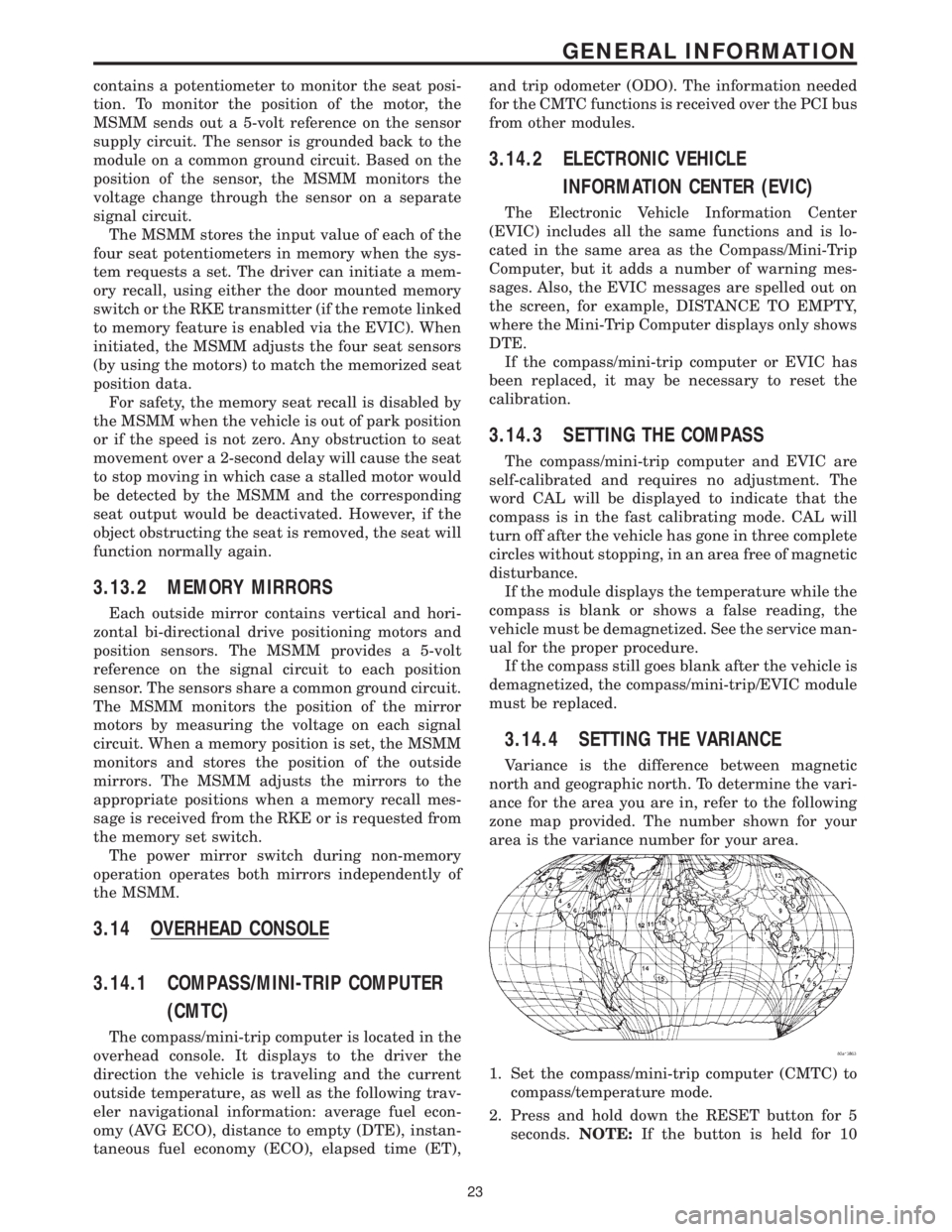
3.14.4 SETTING THE VARIANCE
Variance is the difference between magnetic
north and geographic north. To determine the vari-
ance for the area you are in, refer to the following
zone map provided. The number shown for your
area is the variance number for your area.
1. Set the compass/mini-trip computer (CMTC) to
compass/temperature mode.
2. Press and hold down the RESET button for 5
seconds.NOTE:If the button is held for 10
23
GENERAL INFORMATION
Page 59 of 4284
WARNING: BEFORE ROAD TESTING A
VEHICLE, BE SURE THAT ALL
COMPONENTS ARE REASSEMBLED.
DURING THE TEST DRIVE, DO NOT TRY TO
READ THE DRBIIITSCREEN WHILE IN
MOTION. DO NOT HANG THE DRBIIITFROM
THE REAR VIEW MIRROR OR OPERATE IT
YOURSELF. HAVE AN ASSISTANT
AVAILABLE TO OPERATE THE DRBIIIT.
5.0 REQUIRED TOOLS AND
EQUIPMENT
DRBIIIt(diagnostic read-out box)
Jumper wires
Ohmmeter
Voltmeter
Sentry Key Tester
Test Light
8310 Airbag System Load Tool
8443 SRS Airbag System Load Tool
Diagnostic Junction Port Tester 8339
6.0 GLOSSARY OF TERMS
ABSantilock brake system
ACMairbag control module
AECMairbag electronic control module
(ACM)
ASDMairbag system diagnostic module
(ACM)
AT Cautomatic temperature control
BCMbody control module
CABcontroller antilock brake
CMTCcompass/mini-trip computer
CPAconnector positive assurance
DABdriver airbag
DCHAdiesel cabin heater assist
(cabin heater)
DLCdata link connector
DTCdiagnostic trouble code
DRdriver
EBLelectric back lite (rear window de-
fogger)ECMEngine control module
EVICelectronic vehicle information center
FCMfront control module
GCCGulf Coast Countries
HVACheater ventilation, air conditioning
IPMintelligent power module
LDUlower drive unit
LHDLeft Hand Drive
MICmechanical instrument cluster
MTCmanual temperature control
MSMMmemory seat/mirror module
OBDon board diagnostics
ODOodometer
ORCoccupant restraint controller
PA Bpassenger airbag
PASSpassenger
PCIProgrammable Communication In-
terface (vehicle communication bus)
PCMpowertrain control module
PDCpower distribution center
PLGpower liftgate
PLGMpower liftgate module
PSDpower sliding door
PSDMpower sliding door module
PWMpulse width modulated
RHDRight Hand Drive
RKEremote keyless entry
SABseat airbag
SBTseat belt tensioner
SIACMside impact airbag control module
SKIMsentry key immobilizer module
SKISsentry key immobilizer system
SQUIBalso called initiator (located inside
airbag)
SRSsupplemental restraint system
TCMtransmission control module
VFDvacuum fluorescent display
VTSSvehicle theft security system
30
GENERAL INFORMATION
Page 390 of 4284

Symptom:
MSM MESSAGES NOT RECEIVED
When Monitored and Set Condition:
MSM MESSAGES NOT RECEIVED
When Monitored: With the ignition in run, and the IOD fuse installed.
Set Condition: The BCM does not receive any messages from the Memory Seat Module
(MSM) for at least 0.125 seconds.
POSSIBLE CAUSES
ATTEMPT TO COMMUNICATE WITH THE MEMORY SEAT MODULE
BODY CONTROL MODULE
TEST ACTION APPLICABILITY
1 Turn the ignition on.
With the DRB, enter Body then Memory Seat Module.
Was the DRB able to I/D or communicate with the MSM?All
Ye s®Go To 2
No®Refer to the Communication category for the related symptom(s).
Perform BODY VERIFICATION TEST - VER 1.
2 With the DRB, erase DTC's.
Cycle the ignition switch from off to on and wait approximately 1 minute.
With the DRB, read DTC's.
Did this DTC reset?All
Ye s®Replace the Body Control Module.
Perform BODY VERIFICATION TEST - VER 1.
No®Test Complete.
361
COMMUNICATION
Page 397 of 4284

Symptom:
RADIO MEM MSG NOT RECEIVED
When Monitored and Set Condition:
RADIO MEM MSG NOT RECEIVED
When Monitored: With the ignition in run, and the IOD fuse installed.
Set Condition:
POSSIBLE CAUSES
ATTEMPT TO COMMUNICATE WITH THE RADIO
CHECK THE MEMORY SYSTEM
BODY CONTROL MODULE
TEST ACTION APPLICABILITY
1 Turn the ignition on.
With the DRB, attempt to communicate with the Radio.
Was the DRB able to I/D or communicate with the Radio?All
Ye s®Go To 2
No®Refer to the Communication category for the related symptom(s).
Perform BODY VERIFICATION TEST - VER 1.
2 Turn the ignition on.
Operate the memory seat system.
Did the memory seat system operate properly?All
Ye s®Go To 3
No®Refer to the Memory Seat category and perform the appropriate
symptom.
Perform BODY VERIFICATION TEST - VER 1.
3 With the DRB, erase DTC's.
Cycle the ignition switch from off to on and wait approximately 1 minute.
With the DRB, read DTC's.
Did this DTC reset?All
Ye s®Replace the Body Control Module.
Perform BODY VERIFICATION TEST - VER 1.
No®Test Complete.
368
COMMUNICATION
Page 404 of 4284
Symptom:
*BUS +/- SIGNALS OPEN FROM MEMORY SEAT/MIRROR MODULE
POSSIBLE CAUSES
ATTEMPT TO COMMUNICATE WITH THE BCM
FUSED SEAT SWITCH DRIVER CIRCUIT OPEN
GROUND CIRCUIT OPEN
OPEN PCI BUS CIRCUIT
MEMORY SEAT/MIRROR MODULE
TEST ACTION APPLICABILITY
1 Turn the ignition on.
With the DRB, enter Body then Body Computer.
Was the DRB able to I/D or communicate with the BCM?All
Ye s®Go To 2
No®Refer to the symptom list for problems related to no communica-
tion with the BCM.
Perform MEMORY SYSTEM VERIFICATION TEST - VER 1.
2 Turn the ignition off.
Disconnect the Memory Seat/Mirror Module C4 harness connector.
Using a 12-volt test light connected to ground, probe the Fused Seat Switch Driver
circuit.
Is the test light illuminated?All
Ye s®Go To 3
No®Check the Power Seat Circuit Breaker for an open or short. If ok,
repair the Fused Seat Switch Driver circuit for an open or short.
Perform MEMORY SYSTEM VERIFICATION TEST - VER 1.
3 Turn the ignition off.
Disconnect the Memory Seat/Mirror Module C4 harness connector.
Measure the resistance between ground and the ground circuit.
Is the resistance below 5.0 ohms?All
Ye s®Go To 4
No®Repair the ground circuit for an open.
Perform MEMORY SYSTEM VERIFICATION TEST - VER 1.
375
COMMUNICATION
Page 405 of 4284
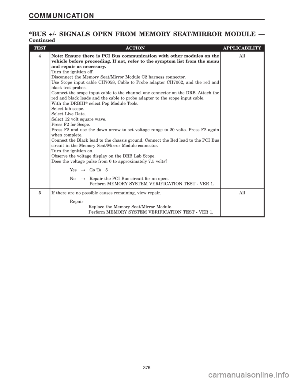
TEST ACTION APPLICABILITY
4Note: Ensure there is PCI Bus communication with other modules on the
vehicle before proceeding. If not, refer to the symptom list from the menu
and repair as necessary.
Turn the ignition off.
Disconnect the Memory Seat/Mirror Module C2 harness connector.
Use Scope input cable CH7058, Cable to Probe adapter CH7062, and the red and
black test probes.
Connect the scope input cable to the channel one connector on the DRB. Attach the
red and black leads and the cable to probe adapter to the scope input cable.
With the DRBIIItselect Pep Module Tools.
Select lab scope.
Select Live Data.
Select 12 volt square wave.
Press F2 for Scope.
Press F2 and use the down arrow to set voltage range to 20 volts. Press F2 again
when complete.
Connect the Black lead to the chassis ground. Connect the Red lead to the PCI Bus
circuit in the Memory Seat/Mirror Module connector.
Turn the ignition on.
Observe the voltage display on the DRB Lab Scope.
Does the voltage pulse from 0 to approximately 7.5 volts?All
Ye s®Go To 5
No®Repair the PCI Bus circuit for an open.
Perform MEMORY SYSTEM VERIFICATION TEST - VER 1.
5 If there are no possible causes remaining, view repair. All
Repair
Replace the Memory Seat/Mirror Module.
Perform MEMORY SYSTEM VERIFICATION TEST - VER 1.
376
COMMUNICATION
*BUS +/- SIGNALS OPEN FROM MEMORY SEAT/MIRROR MODULE Ð
Continued