2001 CHRYSLER VOYAGER compression ratio
[x] Cancel search: compression ratioPage 1413 of 4284
Symptom:
*CHECKING THE ENGINE MECHANICAL SYSTEMS
POSSIBLE CAUSES
CHECKING ENGINE MECHANICAL SYSTEMS
TEST ACTION APPLICABILITY
1NOTE: The following items should be checked as a possible cause of a
Driveability or No-Start problem.
WARNING: Do not attempt to remove or separate high pressure fuel line.
Attempting to do so could result in severe bodily injury or death.
Engine Valve Timing - must be within specification
Engine Compression - must be within specifications
Camshaft Lobes - check for abnormal wear
Camshaft Position Sensor - check the camshaft position sensor tooth for debris and
deterioration
Crankshaft Position Sensor - check the crankshaft tone wheel for debris and
deterioration
Engine Exhaust System - must be free of any restriction
Engine Drive Sprocket - must be properly positioned
Power Brake Booster - must be free of any vacuum leaks
Fuel - must have adequate supply and must be free of contamination and gasoline
Fuel Injectors - must not be plugged or restricted
Fuel Injection Pump - must be producing the correct output volume and pressure
Inspect the Fuel Lines, Fuel Filter and Fuel Pressure Relief Valve for signs of
restriction and leaks
NOTE: Check for any Technical Service Bulletins that may relate to the
problem.
Are there any problems evident?All
Ye s®Repair as necessary.
Perform ROAD TEST VERIFICATION - VER-2.
No®Test Complete.
194
DRIVEABILITY - DIESEL
Page 1552 of 4284
INSTALLATION - AWD AND HEAVY DUTY
(1) Install jounce bumper through bumper support
plate and thread into welded nut in frame rail.
(2) Tighten the jounce bumper to 33 N´m (290 in.
lbs.) torque.
INSTALLATION - FRONT-WHEEL-DRIVE
(1) Hook the forward end of the jounce bumper
bracket in the mounting hole of the frame rail, then
install the mounting bolt in the opposite end, secur-
ing the bumper to the frame rail. Tighten the jounce
bumper mounting bolt to 33 N´m (290 in. lbs.) torque.
SHOCK ABSORBER
DESCRIPTION
There is one shock absorber on each side of the
rear suspension. The top of each shock absorber is
bolted to the frame rail. The bottom of each shock
absorber is bolted to the rear axle.
This vehicle is available with either standard type
or load-leveling shock absorbers. On the exterior,
load-leveling shock absorbers are larger in diameter
than standard shock absorbers. The load-leveling
shock absorbers mount the same as the standard
shock absorbers.
OPERATION
The shock absorber dampens jounce and rebound
motions of the spring and suspension.
Each load-leveling shock absorber is a self-leveling,
self-contained vehicle leveling system and shock
absorber combined. It does not require an external
compressor, hoses, or height leveling sensors. All the
height leveling sensors, hydraulic pump, etc., are
contained inside the shock absorber. It uses road
inputs (bumps, stops, starts, turns, acceleration,
deceleration, etc.) to activate pumping, which results
in the extension and compression of the shock
absorber.
REMOVAL - SHOCK ABSORBER
(1) Raise vehicle. (Refer to LUBRICATION &
MAINTENANCE/HOISTING - STANDARD PROCE-
DURE)
(2) Support the rear axle of the vehicle using 2
jackstands positioned at the outer ends of the axle.
NOTE: If the shock absorber lower mounting bolt
deflects upward during removal, raise axle by
adjusting the support jack. If the lower shock
absorber bolt deflects downward during removal,
lower the axle by adjusting the support jack.
(3) Remove the shock absorber lower mounting
bolt.
(4) While holding shock absorber, remove the
shock absorber upper mounting bolt and shock
absorber.
DISASSEMBLY - SHOCK ABSORBER (UPPER
BUSHING)
(1) Remove the shock absorber from the vehicle.
(2) Install the Receiver, Special Tool 8526-1, into
the cup of the Ball Joint Press, Special Tool C-4212F,
and tighten the set screw. Install the Driver, Special
Tool 8526-2, on the tip of the Ball Joint Press screw
drive as shown (Fig. 23).
Fig. 21 Jounce Bumper
1 - JOUNCE BUMPER
Fig. 22 Jounce Bumper - FWD
1-JOUNCE BUMPER
2 - 36 REARRS
JOUNCE BUMPER (Continued)
Page 1922 of 4284
IGNITION COIL
DESCRIPTION
The ignition coil assembly consists of 2 or 3 inde-
pendent coils molded together (Fig. 10) or (Fig. 11).
The coil assembly for the 3.3/3.8L is mounted on the
intake manifold. The coil assembly for the 2.4L is
mounted on the cylinder head cover. Spark plug
cables route to each cylinder from the coil.
OPERATION
The coil fires two spark plugs every power stroke.
One plug is the cylinder under compression, the
other cylinder fires on the exhaust stroke. The Pow-
ertrain Control Module (PCM) determines which of
the coils to charge and fire at the correct time.
The Auto Shutdown (ASD) relay provides battery
voltage to the ignition coil. The PCM provides a
ground contact (circuit) for energizing the coil. When
the PCM breaks the contact, the magnetic energy in
the coil transfers to the secondary causing the spark.
The PCM will de-energize the ASD relay if it does
not receive the crankshaft position sensor and cam-
shaft position sensor inputs. Refer to Auto Shutdown
(ASD) RelayÐPCM Output, in this section for relay
operation.
REMOVAL - 2.4L
The electronic ignition coil pack attaches directly
to the valve cover.
(1) Diconnect the negative battery cable.
(2) Disconnect electrical connector from coil pack
(3) Remove coil pack mounting bolts.(4) Remove coil pack and heat shield (Fig. 10).
REMOVAL - 3.3/3.8L
(1) Disconnect the negative battery cable.
(2) Remove the throttle and speed control cables
from clip.
(3) Remove 2 bolts from the Power steering reser-
voir to intake manifold.
(4) Loosen the lower nut for the power steering
reservoir from stud on ignition coil bracket.
(5) Reposition the Power steering reservoir (Fig.
12).
(6) Remove the ignition cables from the ignition
coil.
(7) Disconnect the electrical connector from the
ignition coil.
(8) Remove 2 nuts from the ignition coil studs.
(9) Remove 2 bolts from ignition coil, remove coil.
INSTALLATION - 2.4L
(1) Install ignition coil and heat shield to valve
cover and tighten bolts.
(2) Connect the electrical connector to the ignition
coil.
(3) Transfer spark plug cables to new coil pack.
The coil pack towers are numbered with the cylinder
identification. Be sure the ignition cables are fully
seated onto the towers.
(4) Connect the negative battery cable.
Fig. 10 IGNITION COIL - 2.4L
Fig. 11 IGNITION COIL - 3.3/3.8L
1 - IGNITION COIL
8I - 6 IGNITION CONTROLRS
Page 2625 of 4284
ENGINE 2.4L
TABLE OF CONTENTS
page page
ENGINE 2.4L.............................. 1ENGINE 3.3/3.8L......................... 71
ENGINE 2.4L
TABLE OF CONTENTS
page page
ENGINE 2.4L
DESCRIPTION............................3
DIAGNOSIS AND TESTING..................3
CYLINDER COMBUSTION PRESSURE
LEAKAGE TEST.........................3
CYLINDER COMPRESSION PRESSURE
TEST.................................3
ENGINE OIL LEAK INSPECTION............4
ENGINE...............................5
ENGINE DIAGNOSIS - PERFORMANCE......5
ENGINE DIAGNOSIS - MECHANICAL.........7
STANDARD PROCEDURE...................9
ENGINE CORE AND OIL GALLERY PLUGS....9
REPAIR OF DAMAGED OR WORN
THREADS..............................9
HYDROSTATIC LOCKED ENGINE...........9
FORM-IN-PLACE GASKETS AND SEALERS. . . 10
ENGINE GASKET SURFACE PREPARATION . . 11
MEASURING WITH PLASTIGAGE..........11
REMOVAL..............................12
INSTALLATION...........................13
SPECIFICATIONS........................16
SPECIAL TOOLS.........................19
AIR CLEANER ELEMENT
REMOVAL..............................22
INSTALLATION...........................22
AIR CLEANER HOUSING
REMOVAL..............................22
INSTALLATION...........................22
CYLINDER HEAD
DESCRIPTION...........................22
OPERATION.............................23
DIAGNOSIS AND TESTING.................23
CYLINDER HEAD GASKET...............23
REMOVAL..............................23
CLEANING..............................24
INSPECTION............................24
INSTALLATION...........................24CAMSHAFT OIL SEAL(S)
REMOVAL..............................26
INSTALLATION...........................26
CAMSHAFT(S)
DESCRIPTION...........................26
OPERATION.............................27
STANDARD PROCEDURE..................27
CAMSHAFT END-PLAY..................27
REMOVAL..............................27
CLEANING..............................28
INSPECTION............................28
INSTALLATION...........................28
CYLINDER HEAD COVER
REMOVAL..............................29
CLEANING..............................29
INSPECTION............................29
INSTALLATION...........................29
INTAKE/EXHAUST VALVES & SEATS
DESCRIPTION...........................30
CLEANING..............................30
VALVE SPRINGS
REMOVAL..............................30
INSPECTION............................31
INSTALLATION...........................31
HYDRAULIC LIFTERS
DIAGNOSIS AND TESTING.................32
LASH ADJUSTER (TAPPET) NOISE
DIAGNOSIS...........................32
REMOVAL..............................32
INSTALLATION...........................32
ROCKER ARMS
REMOVAL..............................33
INSPECTION............................33
INSTALLATION...........................33
ENGINE BLOCK
DESCRIPTION...........................33
STANDARD PROCEDURE..................33
CYLINDER BORE AND PISTON - FITTING....33
CYLINDER BORE HONING...............34
RSENGINE 2.4L9-1
Page 2630 of 4284
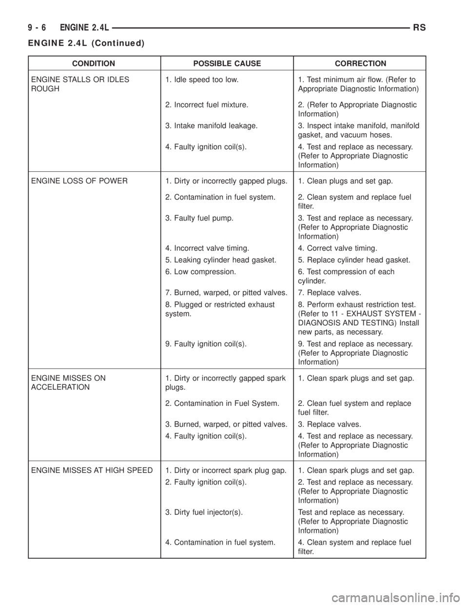
CONDITION POSSIBLE CAUSE CORRECTION
ENGINE STALLS OR IDLES
ROUGH1. Idle speed too low. 1. Test minimum air flow. (Refer to
Appropriate Diagnostic Information)
2. Incorrect fuel mixture. 2. (Refer to Appropriate Diagnostic
Information)
3. Intake manifold leakage. 3. Inspect intake manifold, manifold
gasket, and vacuum hoses.
4. Faulty ignition coil(s). 4. Test and replace as necessary.
(Refer to Appropriate Diagnostic
Information)
ENGINE LOSS OF POWER 1. Dirty or incorrectly gapped plugs. 1. Clean plugs and set gap.
2. Contamination in fuel system. 2. Clean system and replace fuel
filter.
3. Faulty fuel pump. 3. Test and replace as necessary.
(Refer to Appropriate Diagnostic
Information)
4. Incorrect valve timing. 4. Correct valve timing.
5. Leaking cylinder head gasket. 5. Replace cylinder head gasket.
6. Low compression. 6. Test compression of each
cylinder.
7. Burned, warped, or pitted valves. 7. Replace valves.
8. Plugged or restricted exhaust
system.8. Perform exhaust restriction test.
(Refer to 11 - EXHAUST SYSTEM -
DIAGNOSIS AND TESTING) Install
new parts, as necessary.
9. Faulty ignition coil(s). 9. Test and replace as necessary.
(Refer to Appropriate Diagnostic
Information)
ENGINE MISSES ON
ACCELERATION1. Dirty or incorrectly gapped spark
plugs.1. Clean spark plugs and set gap.
2. Contamination in Fuel System. 2. Clean fuel system and replace
fuel filter.
3. Burned, warped, or pitted valves. 3. Replace valves.
4. Faulty ignition coil(s). 4. Test and replace as necessary.
(Refer to Appropriate Diagnostic
Information)
ENGINE MISSES AT HIGH SPEED 1. Dirty or incorrect spark plug gap. 1. Clean spark plugs and set gap.
2. Faulty ignition coil(s). 2. Test and replace as necessary.
(Refer to Appropriate Diagnostic
Information)
3. Dirty fuel injector(s). Test and replace as necessary.
(Refer to Appropriate Diagnostic
Information)
4. Contamination in fuel system. 4. Clean system and replace fuel
filter.
9 - 6 ENGINE 2.4LRS
ENGINE 2.4L (Continued)
Page 2640 of 4284
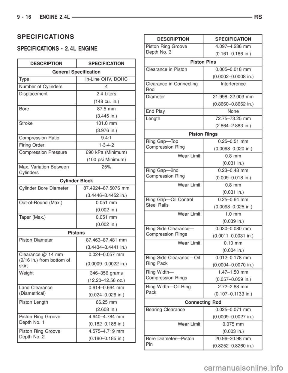
SPECIFICATIONS
SPECIFICATIONS - 2.4L ENGINE
DESCRIPTION SPECIFICATION
General Specification
Type In-Line OHV, DOHC
Number of Cylinders 4
Displacement 2.4 Liters
(148 cu. in.)
Bore 87.5 mm
(3.445 in.)
Stroke 101.0 mm
(3.976 in.)
Compression Ratio 9.4:1
Firing Order 1-3-4-2
Compression Pressure 690 kPa (Minimum)
(100 psi Minimum)
Max. Variation Between
Cylinders25%
Cylinder Block
Cylinder Bore Diameter 87.4924±87.5076 mm
(3.4446±3.4452 in.)
Out-of-Round (Max.) 0.051 mm
(0.002 in.)
Taper (Max.) 0.051 mm
(0.002 in.)
Pistons
Piston Diameter 87.463±87.481 mm
(3.4434±3.4441 in.)
Clearance @ 14 mm
(9/16 in.) from bottom of
skirt0.024±0.057 mm
(0.0009±0.0022 in.)
Weight 346±356 grams
(12.20±12.56 oz.)
Land Clearance
(Diametrical)0.614±0.664 mm
(0.024±0.026 in.)
Piston Length 66.25 mm
(2.608 in.)
Piston Ring Groove
Depth No. 14.640±4.784 mm
(0.182±0.188 in.)
Piston Ring Groove
Depth No. 24.575±4.719 mm
(0.180±0.185 in.)
DESCRIPTION SPECIFICATION
Piston Ring Groove
Depth No. 34.097±4.236 mm
(0.161±0.166 in.)
Piston Pins
Clearance in Piston 0.005±0.018 mm
(0.0002±0.0008 in.)
Clearance in Connecting
RodInterference
Diameter 21.998±22.003 mm
(0.8660±0.8662 in.)
End Play None
Length 72.75±73.25 mm
(2.864±2.883 in.)
Piston Rings
Ring GapÐTop
Compression Ring0.25±0.51 mm
(0.0098±0.020 in.)
Wear Limit 0.8 mm
(0.031 in.)
Ring GapÐ2nd
Compression Ring0.23±0.48 mm
(0.009±0.018 in.)
Wear Limit 0.8 mm
(0.031 in.)
Ring GapÐOil Control
Steel Rails0.25±0.64 mm
(0.0098±0.025 in.)
Wear Limit 1.0 mm
(0.039 in.)
Ring Side ClearanceÐ
Compression Rings0.030±0.080 mm
(0.0011±0.0031 in.)
Wear Limit 0.10 mm
(0.004 in.)
Ring Side ClearanceÐOil
Ring Pack0.012±0.178 mm
(0.0004±0.0070 in.)
Ring WidthÐ
Compression Rings1.47±1.50 mm
(0.057±0.059 in.)
Ring WidthÐOil Ring
Pack2.72±2.88 mm
(0.107±0.1133 in.)
Connecting Rod
Bearing Clearance 0.025±0.071 mm
(0.0009±0.0027 in.)
Wear Limit 0.075 mm
(0.003 in.)
Bore DiameterÐPiston
Pin20.96±20.98 mm
(0.8252±0.8260 in.)
9 - 16 ENGINE 2.4LRS
Page 2647 of 4284
OPERATION
The cylinder head closes the combustion chamber,
allowing the pistons to compress the fuel/air mixture
for ignition. The valves are actuated by the lobe pro-
files on the camshaft to open and close at specified
duration to either allow clean air in the combustion
chamber or the exhaust gases out; depending on the
stroke of the engine.
DIAGNOSIS AND TESTINGÐCYLINDER HEAD
GASKET
A cylinder head gasket leak can be located between
adjacent cylinders or between a cylinder and the
adjacent water jacket.
Possible indications of the cylinder head gasket
leaking between adjacent cylinders are:
²Loss of engine power
²Engine misfiring
²Poor fuel economy
Possible indications of the cylinder head gasket
leaking between a cylinder and an adjacent water
jacket are:
²Engine overheating
²Loss of coolant
²Excessive steam (white smoke) emitting from
exhaust
²Coolant foaming
CYLINDER-TO-CYLINDER LEAKAGE TEST
To determine if an engine cylinder head gasket is
leaking between adjacent cylinders, follow the proce-
dures in Cylinder Compression Pressure Test (Refer
to 9 - ENGINE - DIAGNOSIS AND TESTING). An
engine cylinder head gasket leaking between adja-
cent cylinders will result in approximately a 50±70%
reduction in compression pressure.
CYLINDER-TO-WATER JACKET LEAKAGE TEST
WARNING: USE EXTREME CAUTION WHEN THE
ENGINE IS OPERATING WITH COOLANT PRES-
SURE CAP REMOVED.
VISUAL TEST METHOD
With the engine cool, remove the coolant pressure
cap. Start the engine and allow it to warm up until
thermostat opens.
If a large combustion/compression pressure leak
exists, bubbles will be visible in the coolant.
COOLING SYSTEM TESTER METHOD
WARNING: WITH COOLING SYSTEM TESTER IN
PLACE, PRESSURE WILL BUILD UP FAST. EXCES-
SIVE PRESSURE BUILT UP, BY CONTINUOUS
ENGINE OPERATION, MUST BE RELEASED TO A
SAFE PRESSURE POINT. NEVER PERMIT PRES-
SURE TO EXCEED 138 kPa (20 psi).
Install Cooling System Tester 7700 or equivalent to
pressure cap neck. Start the engine and observe the
tester's pressure gauge. If gauge pulsates with every
power stroke of a cylinder a combustion pressure
leak is evident.
CHEMICAL TEST METHOD
Combustion leaks into the cooling system can also
be checked by using Bloc-Chek Kit C-3685-A or
equivalent. Perform test following the procedures
supplied with the tool kit.
REMOVAL - CYLINDER HEAD
(1) Perform fuel system pressure release procedure
before attempting any repairs.(Refer to 14 -
FUEL SYSTEM/FUEL DELIVERY - SPECIFICA-
TIONS)
(2) Disconnect battery negative cable.
(3) Drain cooling system. (Refer to 7 - COOLING -
STANDARD PROCEDURE)
(4) Remove air filter housing and inlet tube.
(5) Remove upper intake manifold. (Refer to 9 -
ENGINE/MANIFOLDS/INTAKE MANIFOLD -
REMOVAL)
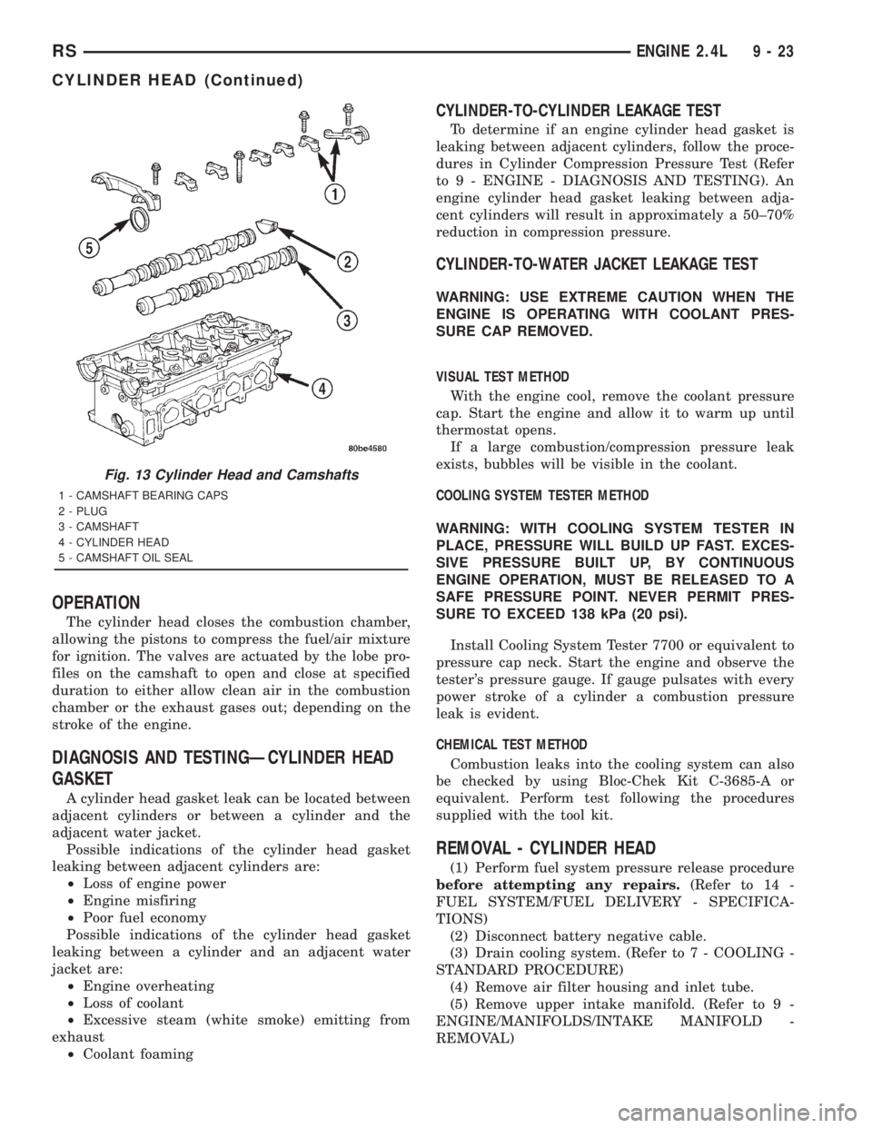
Fig. 13 Cylinder Head and Camshafts
1 - CAMSHAFT BEARING CAPS
2 - PLUG
3 - CAMSHAFT
4 - CYLINDER HEAD
5 - CAMSHAFT OIL SEAL
RSENGINE 2.4L9-23
CYLINDER HEAD (Continued)
Page 2667 of 4284
(4) Pistons and connecting rods must be removed
from top of cylinder block. Rotate crankshaft so that
each connecting rod is centered in cylinder bore.
(5) Remove Balance Shaft Assembly. Refer to Bal-
ance Shaft Removal in this section.
(6) Remove connecting rod cap bolts. Push each
piston and rod assembly out of cylinder bore.NOTE: Be careful not to nick crankshaft journals.
(7) After removal, install bearing cap on the mat-
ing rod.
(8) Piston and Rods are serviced as an assembly.
INSTALLATION
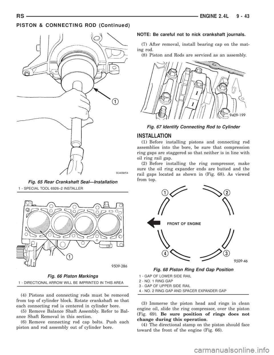
(1) Before installing pistons and connecting rod
assemblies into the bore, be sure that compression
ring gaps are staggered so that neither is in line with
oil ring rail gap.
(2) Before installing the ring compressor, make
sure the oil ring expander ends are butted and the
rail gaps located as shown in (Fig. 68). As viewed
from top.
(3) Immerse the piston head and rings in clean
engine oil, slide the ring compressor, over the piston
(Fig. 69).Be sure position of rings does not
change during this operation.
(4) The directional stamp on the piston should face
toward the front of the engine (Fig. 66).
Fig. 65 Rear Crankshaft SealÐInstallation
1 - SPECIAL TOOL 6926±2 INSTALLER
Fig. 66 Piston Markings
1 - DIRECTIONAL ARROW WILL BE IMPRINTED IN THIS AREA
Fig. 67 Identify Connecting Rod to Cylinder
Fig. 68 Piston Ring End Gap Position
1 - GAP OF LOWER SIDE RAIL
2 - NO. 1 RING GAP
3 - GAP OF UPPER SIDE RAIL
4 - NO. 2 RING GAP AND SPACER EXPANDER GAP
RSENGINE 2.4L9-43
PISTON & CONNECTING ROD (Continued)