2001 CHRYSLER VOYAGER compression ratio
[x] Cancel search: compression ratioPage 2695 of 4284
ENGINE 3.3/3.8L
TABLE OF CONTENTS
page page
ENGINE 3.3/3.8L
DESCRIPTION...........................73
DIAGNOSIS AND TESTING.................74
ENGINE..............................74
ENGINE DIAGNOSIS - PERFORMANCE......74
ENGINE DIAGNOSIS - MECHANICAL........76
ENGINE OIL LEAK INSPECTION...........77
CYLINDER COMPRESSION PRESSURE
TEST................................78
CYLINDER COMBUSTION PRESSURE
LEAKAGE TEST........................79
STANDARD PROCEDURE..................79
MEASURING WITH PLASTIGAGE..........79
FORM-IN-PLACE GASKETS AND SEALERS. . . 79
ENGINE GASKET SURFACE PREPARATION . . 80
HYDROSTATIC LOCKED ENGINE..........81
REPAIR OF DAMAGED OR WORN
THREADS.............................81
ENGINE CORE AND OIL GALLERY PLUGS . . . 81
REMOVAL..............................82
INSTALLATION...........................84
SPECIFICATIONS........................86
SPECIAL TOOLS.........................90
AIR CLEANER ELEMENT
REMOVAL..............................93
INSTALLATION...........................93
AIR CLEANER HOUSING
REMOVAL..............................93
INSTALLATION...........................93
CYLINDER HEAD
DESCRIPTION...........................94
OPERATION.............................94
DIAGNOSIS AND TESTING.................94
CYLINDER HEAD GASKET...............94
REMOVAL..............................95
CLEANING..............................95
INSPECTION............................96
INSTALLATION...........................96
CYLINDER HEAD COVER(S)
DESCRIPTION...........................97
CYLINDER HEAD COVER - RIGHT
REMOVAL..............................97
INSTALLATION...........................98
CYLINDER HEAD COVER - LEFT
REMOVAL..............................98
INSTALLATION...........................99
INTAKE/EXHAUST VALVES & SEATS
DESCRIPTION...........................99
OPERATION.............................99STANDARD PROCEDURE..................99
VALVE SERVICE.......................99
REMOVAL.............................100
CLEANING.............................100
INSPECTION...........................100
INSTALLATION..........................101
VALVE SPRINGS
DESCRIPTION..........................101
OPERATION............................101
REMOVAL.............................101
INSPECTION...........................103
INSTALLATION..........................103
ROCKER ARMS
DESCRIPTION..........................103
OPERATION............................104
REMOVAL.............................104
DISASSEMBLY..........................105
ASSEMBLY............................105
INSTALLATION..........................105
VALVE STEM SEALS
DESCRIPTION..........................106
REMOVAL.............................106
INSTALLATION..........................106
ENGINE BLOCK
DESCRIPTION..........................106
STANDARD PROCEDURE.................106
CYLINDER BORE HONING...............106
CLEANING.............................107
INSPECTION...........................107
CAMSHAFT & BEARINGS (IN BLOCK)
DESCRIPTION..........................107
OPERATION............................107
REMOVAL.............................107
INSPECTION...........................108
INSTALLATION..........................108
CONNECTING ROD BEARINGS
STANDARD PROCEDURE.................109
CONNECTING ROD BEARING - FITTING....109
CRANKSHAFT
DESCRIPTION..........................109
OPERATION............................110
STANDARD PROCEDURE.................110
CRANKSHAFT END PLAY................110
REMOVAL.............................110
INSPECTION...........................111
INSTALLATION..........................111
CRANKSHAFT MAIN BEARINGS
STANDARD PROCEDURE.................113
CRANKSHAFT MAIN BEARING - FITTING . . . 113
RSENGINE 3.3/3.8L9-71
Page 2699 of 4284
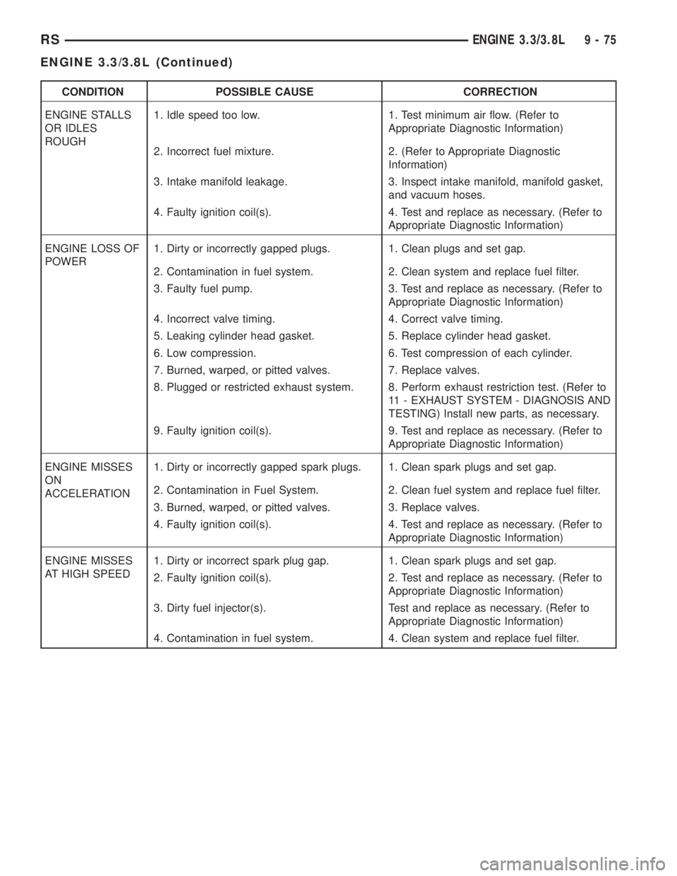
CONDITION POSSIBLE CAUSE CORRECTION
ENGINE STALLS
OR IDLES
ROUGH1. Idle speed too low. 1. Test minimum air flow. (Refer to
Appropriate Diagnostic Information)
2. Incorrect fuel mixture. 2. (Refer to Appropriate Diagnostic
Information)
3. Intake manifold leakage. 3. Inspect intake manifold, manifold gasket,
and vacuum hoses.
4. Faulty ignition coil(s). 4. Test and replace as necessary. (Refer to
Appropriate Diagnostic Information)
ENGINE LOSS OF
POWER1. Dirty or incorrectly gapped plugs. 1. Clean plugs and set gap.
2. Contamination in fuel system. 2. Clean system and replace fuel filter.
3. Faulty fuel pump. 3. Test and replace as necessary. (Refer to
Appropriate Diagnostic Information)
4. Incorrect valve timing. 4. Correct valve timing.
5. Leaking cylinder head gasket. 5. Replace cylinder head gasket.
6. Low compression. 6. Test compression of each cylinder.
7. Burned, warped, or pitted valves. 7. Replace valves.
8. Plugged or restricted exhaust system. 8. Perform exhaust restriction test. (Refer to
11 - EXHAUST SYSTEM - DIAGNOSIS AND
TESTING) Install new parts, as necessary.
9. Faulty ignition coil(s). 9. Test and replace as necessary. (Refer to
Appropriate Diagnostic Information)
ENGINE MISSES
ON
ACCELERATION1. Dirty or incorrectly gapped spark plugs. 1. Clean spark plugs and set gap.
2. Contamination in Fuel System. 2. Clean fuel system and replace fuel filter.
3. Burned, warped, or pitted valves. 3. Replace valves.
4. Faulty ignition coil(s). 4. Test and replace as necessary. (Refer to
Appropriate Diagnostic Information)
ENGINE MISSES
AT HIGH SPEED1. Dirty or incorrect spark plug gap. 1. Clean spark plugs and set gap.
2. Faulty ignition coil(s). 2. Test and replace as necessary. (Refer to
Appropriate Diagnostic Information)
3. Dirty fuel injector(s). Test and replace as necessary. (Refer to
Appropriate Diagnostic Information)
4. Contamination in fuel system. 4. Clean system and replace fuel filter.
RSENGINE 3.3/3.8L9-75
ENGINE 3.3/3.8L (Continued)
Page 2710 of 4284
(43) Connect the vacuum hoses to the throttle
body.
(44) Connect the EGR transducer electrical connec-
tor.
(45) Connect the TPS, IAC, and MAP sensor elec-
trical connectors.
(46) Connect throttle cables to throttle body.
(47) Install the radiator fans. (Refer to 7 - COOL-
ING/ENGINE/RADIATOR FAN - INSTALLATION)
(48) Connect the radiator upper hose.
(49) Connect the heater hoses. Remove pinch-off
pliers from the rear heater hoses, if equipped.
(50) Install the radiator upper support crossmem-
ber. (Refer to 23 - BODY/EXTERIOR/GRILLE OPEN-
ING REINFORCEMENT - INSTALLATION)
(51) Install the wiper module. (Refer to 8 - ELEC-
TRICAL/WIPERS/WASHERS/WIPER MODULE -
INSTALLATION)
(52) Connect the fuel line to fuel rail. (Refer to 14
- FUEL SYSTEM/FUEL DELIVERY/FUEL LINES -
STANDARD PROCEDURE)
(53) Install the air cleaner and hoses.
(54) Install new oil filter. Fill engine crankcase
with proper oil to correct level.
(55) Connect negative cable to battery.
(56) Fill the cooling system. (Refer to 7 - COOL-
ING - STANDARD PROCEDURE)
(57) Start engine and run until operating temper-
ature is reached.
(58) Adjust transmission linkage, if necessary.
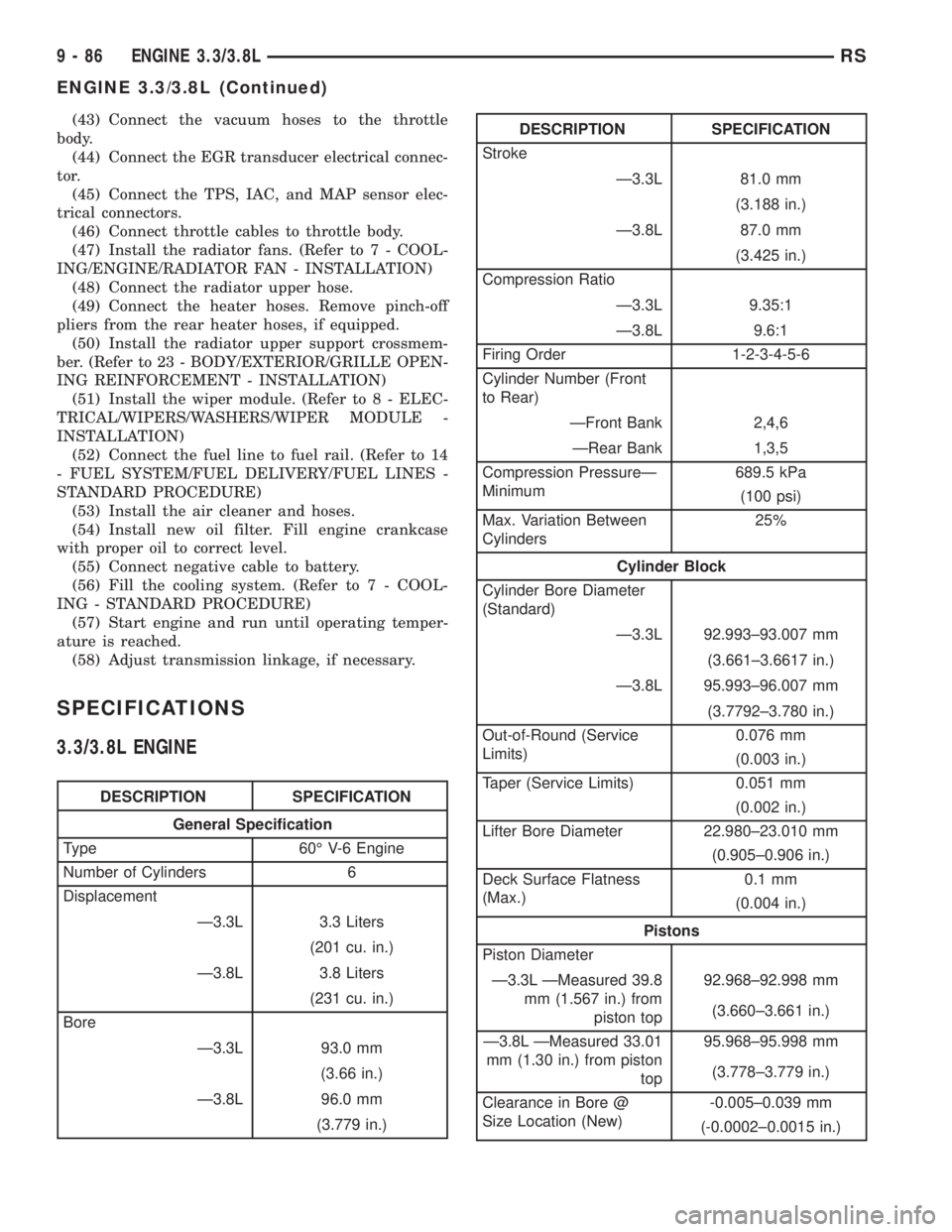
SPECIFICATIONS
3.3/3.8L ENGINE
DESCRIPTION SPECIFICATION
General Specification
Type 60É V-6 Engine
Number of Cylinders 6
Displacement
Ð3.3L 3.3 Liters
(201 cu. in.)
Ð3.8L 3.8 Liters
(231 cu. in.)
Bore
Ð3.3L 93.0 mm
(3.66 in.)
Ð3.8L 96.0 mm
(3.779 in.)
DESCRIPTION SPECIFICATION
Stroke
Ð3.3L 81.0 mm
(3.188 in.)
Ð3.8L 87.0 mm
(3.425 in.)
Compression Ratio
Ð3.3L 9.35:1
Ð3.8L 9.6:1
Firing Order 1-2-3-4-5-6
Cylinder Number (Front
to Rear)
ÐFront Bank 2,4,6
ÐRear Bank 1,3,5
Compression PressureÐ
Minimum689.5 kPa
(100 psi)
Max. Variation Between
Cylinders25%
Cylinder Block
Cylinder Bore Diameter
(Standard)
Ð3.3L 92.993±93.007 mm
(3.661±3.6617 in.)
Ð3.8L 95.993±96.007 mm
(3.7792±3.780 in.)
Out-of-Round (Service
Limits)0.076 mm
(0.003 in.)
Taper (Service Limits) 0.051 mm
(0.002 in.)
Lifter Bore Diameter 22.980±23.010 mm
(0.905±0.906 in.)
Deck Surface Flatness
(Max.)0.1 mm
(0.004 in.)
Pistons
Piston Diameter
Ð3.3L ÐMeasured 39.8
mm (1.567 in.) from
piston top92.968±92.998 mm
(3.660±3.661 in.)
Ð3.8L ÐMeasured 33.01
mm (1.30 in.) from piston
top95.968±95.998 mm
(3.778±3.779 in.)
Clearance in Bore @
Size Location (New)-0.005±0.039 mm
(-0.0002±0.0015 in.)
9 - 86 ENGINE 3.3/3.8LRS
ENGINE 3.3/3.8L (Continued)
Page 2719 of 4284
CYLINDER-TO-CYLINDER LEAKAGE TEST
To determine if an engine cylinder head gasket is
leaking between adjacent cylinders, follow the proce-
dures in Cylinder Compression Pressure Test (Refer
to 9 - ENGINE - DIAGNOSIS AND TESTING). An
engine cylinder head gasket leaking between adja-
cent cylinders will result in approximately a 50±70%
reduction in compression pressure.
CYLINDER-TO-WATER JACKET LEAKAGE TEST
WARNING: USE EXTREME CAUTION WHEN THE
ENGINE IS OPERATING WITH COOLANT PRES-
SURE CAP REMOVED.
VISUAL TEST METHOD
With the engine cool, remove the coolant pressure
cap. Start the engine and allow it to warm up until
thermostat opens.
If a large combustion/compression pressure leak
exists, bubbles will be visible in the coolant.
COOLING SYSTEM TESTER METHOD
WARNING: WITH COOLING SYSTEM TESTER IN
PLACE, PRESSURE WILL BUILD UP FAST. EXCES-
SIVE PRESSURE BUILT UP, BY CONTINUOUS
ENGINE OPERATION, MUST BE RELEASED TO A
SAFE PRESSURE POINT. NEVER PERMIT PRES-
SURE TO EXCEED 138 kPa (20 psi).
Install Cooling System Tester 7700 or equivalent to
pressure cap neck. Start the engine and observe the
tester's pressure gauge. If gauge pulsates with every
power stroke of a cylinder a combustion pressure
leak is evident.
CHEMICAL TEST METHOD
Combustion leaks into the cooling system can also
be checked by using Bloc-Chek Kit C-3685-A or
equivalent. Perform test following the procedures
supplied with the tool kit.
REMOVAL - CYLINDER HEAD
(1) Drain the cooling system. (Refer to 7 - COOL-
ING - STANDARD PROCEDURE)
(2) Disconnect negative cable from battery.
(3) Remove upper and lower intake manifolds.
(Refer to 9 - ENGINE/MANIFOLDS/INTAKE MANI-
FOLD - REMOVAL)
WARNING: INTAKE MANIFOLD GASKET IS MADE
OF VERY THIN METAL AND MAY CAUSE PER-
SONAL INJURY, HANDLE WITH CARE.(4) Remove the cylinder head covers. (Refer to 9 -
ENGINE/CYLINDER HEAD/CYLINDER HEAD
COVER(S) - REMOVAL)
(5) Remove the spark plugs from cylinder head.
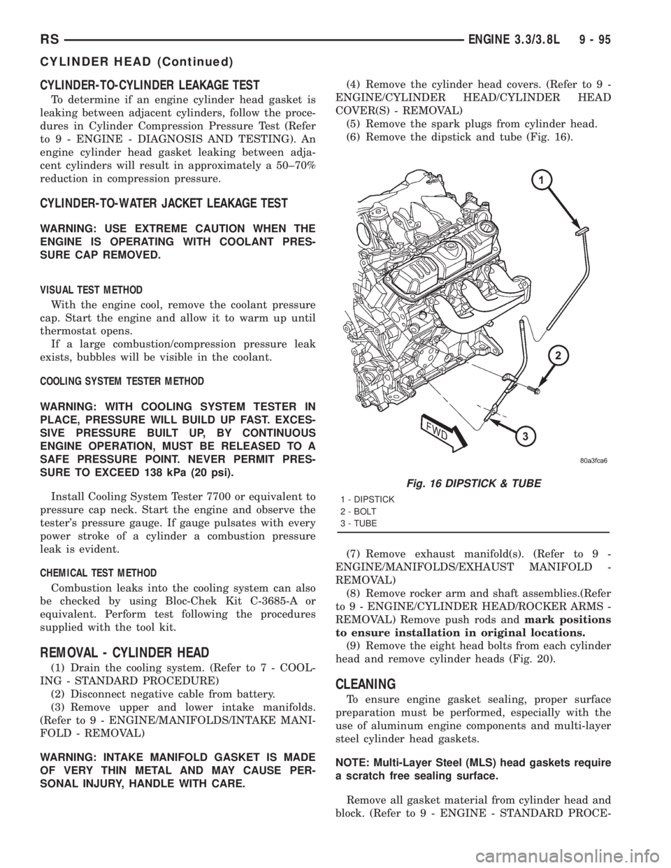
(6) Remove the dipstick and tube (Fig. 16).
(7) Remove exhaust manifold(s). (Refer to 9 -
ENGINE/MANIFOLDS/EXHAUST MANIFOLD -
REMOVAL)
(8) Remove rocker arm and shaft assemblies.(Refer
to 9 - ENGINE/CYLINDER HEAD/ROCKER ARMS -
REMOVAL) Remove push rods andmark positions
to ensure installation in original locations.
(9) Remove the eight head bolts from each cylinder
head and remove cylinder heads (Fig. 20).
CLEANING
To ensure engine gasket sealing, proper surface
preparation must be performed, especially with the
use of aluminum engine components and multi-layer
steel cylinder head gaskets.
NOTE: Multi-Layer Steel (MLS) head gaskets require
a scratch free sealing surface.
Remove all gasket material from cylinder head and
block. (Refer to 9 - ENGINE - STANDARD PROCE-
Fig. 16 DIPSTICK & TUBE
1 - DIPSTICK
2 - BOLT
3 - TUBE
RSENGINE 3.3/3.8L9-95
CYLINDER HEAD (Continued)
Page 2743 of 4284
OIL LEVEL TOO HIGH
If oil level is above the MAX mark on dipstick, it is
possible for the connecting rods to dip into the oil
while engine is running and create foaming. Foam in
oil pan would be fed to the hydraulic lifters by the oil
pump causing them to become soft and allow valves
to seat noisily.
OIL LEVEL TOO LOW
Low oil level may allow pump to take in air which
when fed to the lifters it causes them to become soft
and allows valves to seat noisily. Any leaks on intake
side of pump, through which air can be drawn, will
create the same lifter noise. Check the lubrication
system from the intake strainer to the oil pump
cover, including the relief valve retainer cap. When
lifter noise is due to aeration, it may be intermittent
or constant, and usually more than one lifter will be
noisy. When oil level and leaks have been corrected,
the engine should be operated at fast idle to allow all
of the air inside of the lifters to be bled out.
VALVE TRAIN NOISE
To determine source of valve train noise, operate
engine at idle with cylinder head covers removed and
listen for source of the noise.
NOTE: Worn valve guides or cocked springs are
sometimes mistaken for noisy lifters. If such is the
case, noise may be dampened by applying side
thrust on the valve spring. If noise is not apprecia-
bly reduced, it can be assumed the noise is in the
tappet. Inspect the rocker arm push rod sockets
and push rod ends for wear.
Valve lifter noise ranges from light noise to a
heavy click. A light noise is usually caused by exces-
sive leak-down around the unit plunger which will
necessitate replacing the lifter, or by the plunger par-
tially sticking in the lifter body cylinder. A heavy
click is caused either by a lifter check valve not seat-
ing, or by foreign particles becoming wedged between
the plunger and the lifter body causing the plunger
to stick in the down position. This heavy click will be
accompanied by excessive clearance between the
valve stem and rocker arm as valve closes. In either
case, lifter assembly should be removed for inspec-
tion.
REMOVAL
(1) Remove the cylinder head(s). (Refer to 9 -
ENGINE/CYLINDER HEAD - REMOVAL)
(2) Remove the yoke retainer and aligning yokes
(Fig. 71).
(3) Remove the hydraulic lifters. If necessary use
Special Tool C-4129, or equivalent to remove liftersfrom bores. If lifters are to be reused, identify each
lifter to ensure installation in original location.
INSTALLATION
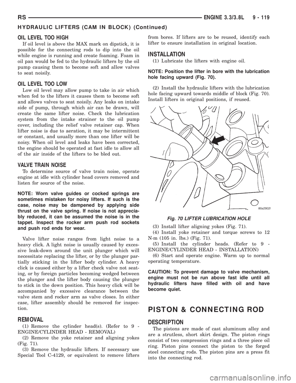
(1) Lubricate the lifters with engine oil.
NOTE: Position the lifter in bore with the lubrication
hole facing upward (Fig. 70).
(2) Install the hydraulic lifters with the lubrication
hole facing upward towards middle of block (Fig. 70).
Install lifters in original positions, if reused.
(3) Install lifter aligning yokes (Fig. 71).
(4) Install yoke retainer and torque screws to 12
N´m (105 in. lbs.) (Fig. 71).
(5) Install the cylinder heads. (Refer to 9 -
ENGINE/CYLINDER HEAD - INSTALLATION)
(6) Start and operate engine. Warm up to normal
operating temperature.
CAUTION: To prevent damage to valve mechanism,
engine must not be run above fast idle until all
hydraulic lifters have filled with oil and have
become quiet.
PISTON & CONNECTING ROD
DESCRIPTION
The pistons are made of cast aluminum alloy and
are a strutless, short skirt design. The piston rings
consist of two compression rings and a three piece oil
ring. Piston pins connect the piston to the forged
steel connecting rods. The piston pins are a press fit
into the connecting rod.
Fig. 70 LIFTER LUBRICATION HOLE
RSENGINE 3.3/3.8L9 - 119
HYDRAULIC LIFTERS (CAM IN BLOCK) (Continued)
Page 2746 of 4284
INSTALLATION
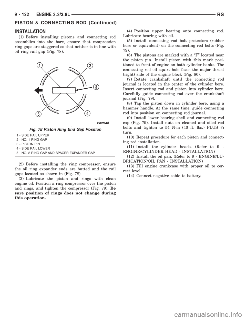
(1) Before installing pistons and connecting rod
assemblies into the bore, ensure that compression
ring gaps are staggered so that neither is in line with
oil ring rail gap (Fig. 78).
(2) Before installing the ring compressor, ensure
the oil ring expander ends are butted and the rail
gaps located as shown in (Fig. 78).
(3) Lubricate the piston and rings with clean
engine oil. Position a ring compressor over the piston
and rings, and tighten the compressor (Fig. 79).Be
sure position of rings does not change during
this operation.(4) Position upper bearing onto connecting rod.
Lubricate bearing with oil.
(5) Install connecting rod bolt protectors (rubber
hose or equivalent) on the connecting rod bolts (Fig.
79).
(6) The pistons are marked with a ªFº located near
the piston pin. Install piston with this mark posi-
tioned to front of engine on both cylinder banks. The
connecting rod oil squirt hole faces the major thrust
(right) side of the engine block (Fig. 80).
(7) Rotate crankshaft until the connecting rod
journal is located in the center of the cylinder bore.
Insert connecting rod and piston into cylinder bore.
Carefully guide connecting rod over the crankshaft
journal (Fig. 79).
(8) Tap the piston down in cylinder bore, using a
hammer handle. At the same time, guide connecting
rod into position on connecting rod journal.
(9) Install lower bearing shell and connecting rod
cap (Fig. 79). Install nuts on cleaned and oiled rod
bolts and tighten to 54 N´m (40 ft. lbs.) PLUS
1¤4
turn.
(10) Repeat procedure for each piston and connect-
ing rod installation.
(11) Install the cylinder heads. (Refer to 9 -
ENGINE/CYLINDER HEAD - INSTALLATION)
(12) Install the oil pan. (Refer to 9 - ENGINE/LU-
BRICATION/OIL PAN - INSTALLATION)
(13) Fill engine crankcase with proper oil to cor-
rect level.
(14) Connect negative cable to battery.Fig. 78 Piston Ring End Gap Position
1 - SIDE RAIL UPPER
2 - NO. 1 RING GAP
3 - PISTON PIN
4 - SIDE RAIL LOWER
5 - NO. 2 RING GAP AND SPACER EXPANDER GAP
9 - 122 ENGINE 3.3/3.8LRS
PISTON & CONNECTING ROD (Continued)
Page 2777 of 4284
INSPECTION
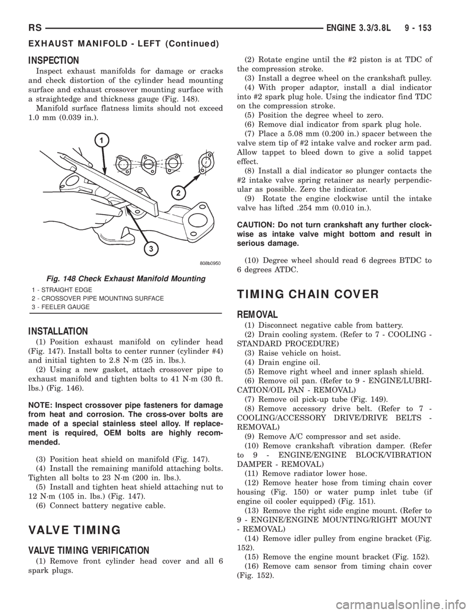
Inspect exhaust manifolds for damage or cracks
and check distortion of the cylinder head mounting
surface and exhaust crossover mounting surface with
a straightedge and thickness gauge (Fig. 148).
Manifold surface flatness limits should not exceed
1.0 mm (0.039 in.).
INSTALLATION
(1) Position exhaust manifold on cylinder head
(Fig. 147). Install bolts to center runner (cylinder #4)
and initial tighten to 2.8 N´m (25 in. lbs.).
(2) Using a new gasket, attach crossover pipe to
exhaust manifold and tighten bolts to 41 N´m (30 ft.
lbs.) (Fig. 146).
NOTE: Inspect crossover pipe fasteners for damage
from heat and corrosion. The cross-over bolts are
made of a special stainless steel alloy. If replace-
ment is required, OEM bolts are highly recom-
mended.
(3) Position heat shield on manifold (Fig. 147).
(4) Install the remaining manifold attaching bolts.
Tighten all bolts to 23 N´m (200 in. lbs.).
(5) Install and tighten heat shield attaching nut to
12 N´m (105 in. lbs.) (Fig. 147).
(6) Connect battery negative cable.
VALVE TIMING
VALVE TIMING VERIFICATION
(1) Remove front cylinder head cover and all 6
spark plugs.(2) Rotate engine until the #2 piston is at TDC of
the compression stroke.
(3) Install a degree wheel on the crankshaft pulley.
(4) With proper adaptor, install a dial indicator
into #2 spark plug hole. Using the indicator find TDC
on the compression stroke.
(5) Position the degree wheel to zero.
(6) Remove dial indicator from spark plug hole.
(7) Place a 5.08 mm (0.200 in.) spacer between the
valve stem tip of #2 intake valve and rocker arm pad.
Allow tappet to bleed down to give a solid tappet
effect.
(8) Install a dial indicator so plunger contacts the
#2 intake valve spring retainer as nearly perpendic-
ular as possible. Zero the indicator.
(9) Rotate the engine clockwise until the intake
valve has lifted .254 mm (0.010 in.).
CAUTION: Do not turn crankshaft any further clock-
wise as intake valve might bottom and result in
serious damage.
(10) Degree wheel should read 6 degrees BTDC to
6 degrees ATDC.
TIMING CHAIN COVER
REMOVAL
(1) Disconnect negative cable from battery.
(2) Drain cooling system. (Refer to 7 - COOLING -
STANDARD PROCEDURE)
(3) Raise vehicle on hoist.
(4) Drain engine oil.
(5) Remove right wheel and inner splash shield.
(6) Remove oil pan. (Refer to 9 - ENGINE/LUBRI-
CATION/OIL PAN - REMOVAL)
(7) Remove oil pick-up tube (Fig. 149).
(8) Remove accessory drive belt. (Refer to 7 -
COOLING/ACCESSORY DRIVE/DRIVE BELTS -
REMOVAL)
(9) Remove A/C compressor and set aside.
(10) Remove crankshaft vibration damper. (Refer
to 9 - ENGINE/ENGINE BLOCK/VIBRATION
DAMPER - REMOVAL)
(11) Remove radiator lower hose.
(12) Remove heater hose from timing chain cover
housing (Fig. 150) or water pump inlet tube (if
engine oil cooler equipped) (Fig. 151).
(13) Remove the right side engine mount. (Refer to
9 - ENGINE/ENGINE MOUNTING/RIGHT MOUNT
- REMOVAL)
(14) Remove idler pulley from engine bracket (Fig.
152).
(15) Remove the engine mount bracket (Fig. 152).
(16) Remove cam sensor from timing chain cover
(Fig. 152).
Fig. 148 Check Exhaust Manifold Mounting
1 - STRAIGHT EDGE
2 - CROSSOVER PIPE MOUNTING SURFACE
3 - FEELER GAUGE
RSENGINE 3.3/3.8L9 - 153
EXHAUST MANIFOLD - LEFT (Continued)
Page 2784 of 4284
OIL FILTER
DESCRIPTION...........................52
REMOVAL..............................53
INSTALLATION...........................53
OIL JET
DESCRIPTION...........................53
REMOVAL..............................53
INSTALLATION...........................53
INTAKE MANIFOLD
DESCRIPTION...........................54
REMOVAL..............................54
INSTALLATION...........................54
VALVE TIMING
STANDARD PROCEDURE..................54
LOCKING ENGINE 90É AFTER TDC.........54
BALANCE SHAFT
DESCRIPTION...........................55OPERATION.............................56
REMOVAL..............................56
INSTALLATION...........................57
TIMING BELT / CHAIN COVER(S)
REMOVAL..............................57
INSTALLATION...........................58
TIMING BELT IDLER PULLEY
REMOVAL..............................59
INSTALLATION...........................60
TIMING BELT/CHAIN TENSIONER
REMOVAL..............................60
INSTALLATION...........................60
ADJUSTMENTS..........................61
TIMING BELT/CHAIN AND SPROCKETS
REMOVAL..............................62
INSTALLATION...........................63
ENGINE 2.5L TURBO DIESEL
DESCRIPTION - 2.5L COMMON RAIL DIESEL
ENGINE
This 2.5 Liter (2500cc) four-cylinder ªcommon railº
direct injection engine is an in-line overhead valve
diesel engine. This engine utilizes a cast iron cylin-
der block and an aluminum cylinder head. The
engine is turbocharged and intercooled. The engine
also has four valves per cylinder and dual overhead
camshafts (Fig. 1).
DESCRIPTION SPECIFICATION
Displacement 2.5L (2499 cc)
Bore 92.00
Stroke 94.00
Compression Ratio 17.5:1
Vacuum at Idle 685.8 mm/Hg (27.0
In/Hg)
Belt Tension Automatic Belt Tensioner
Thermostat Opening 80ÉC 2ÉC
Generator Rating Denso 12V-95A
DESCRIPTION SPECIFICATION
Cooling System Capacity 13.8 Liters W/O Auxiliary
Heater
16.6 Liters With Auxiliary
Heater
Engine Oil Capacity 5.22L W/Filter Change
Timing System Belt Driven Camshafts In
Cylinder Head Cover
Air Intake Dry Filter
Fuel Feed Vane Pump Incorporated
In Injection Pump
Fuel System Direct Fuel Injection
Combustion Cycle 4 Stroke
Cooling System Water Cooling
Injection Pump Rotary Pump and
Electronically Managed
Lubrication Pressure Lubricated By
Rotary Pump
Engine Rotation Clockwise Viewed From
Front Cover
9a - 2 ENGINE 2.5L TURBO DIESELRG