Page 985 of 4284
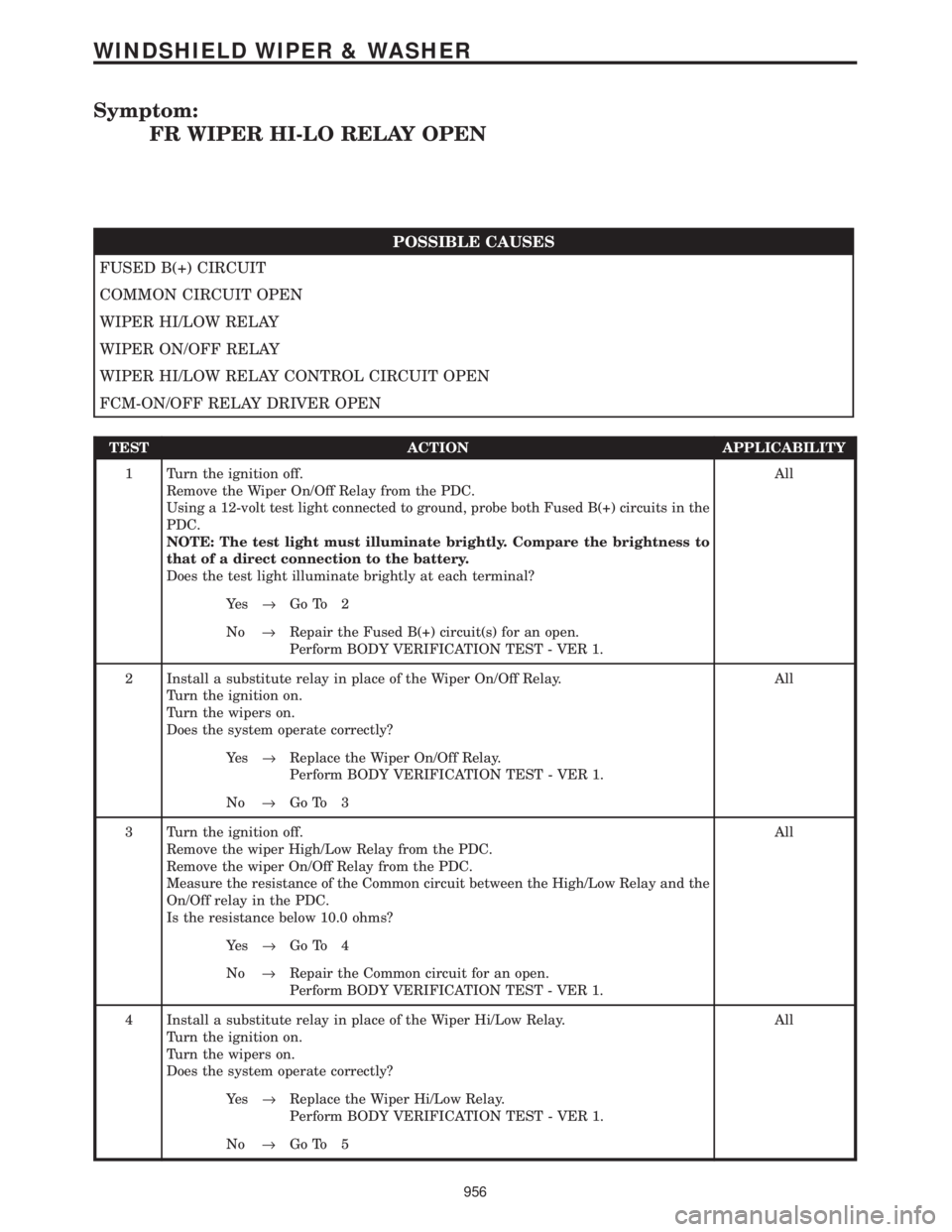
Symptom:
FR WIPER HI-LO RELAY OPEN
POSSIBLE CAUSES
FUSED B(+) CIRCUIT
COMMON CIRCUIT OPEN
WIPER HI/LOW RELAY
WIPER ON/OFF RELAY
WIPER HI/LOW RELAY CONTROL CIRCUIT OPEN
FCM-ON/OFF RELAY DRIVER OPEN
TEST ACTION APPLICABILITY
1 Turn the ignition off.
Remove the Wiper On/Off Relay from the PDC.
Using a 12-volt test light connected to ground, probe both Fused B(+) circuits in the
PDC.
NOTE: The test light must illuminate brightly. Compare the brightness to
that of a direct connection to the battery.
Does the test light illuminate brightly at each terminal?All
Ye s®Go To 2
No®Repair the Fused B(+) circuit(s) for an open.
Perform BODY VERIFICATION TEST - VER 1.
2 Install a substitute relay in place of the Wiper On/Off Relay.
Turn the ignition on.
Turn the wipers on.
Does the system operate correctly?All
Ye s®Replace the Wiper On/Off Relay.
Perform BODY VERIFICATION TEST - VER 1.
No®Go To 3
3 Turn the ignition off.
Remove the wiper High/Low Relay from the PDC.
Remove the wiper On/Off Relay from the PDC.
Measure the resistance of the Common circuit between the High/Low Relay and the
On/Off relay in the PDC.
Is the resistance below 10.0 ohms?All
Ye s®Go To 4
No®Repair the Common circuit for an open.
Perform BODY VERIFICATION TEST - VER 1.
4 Install a substitute relay in place of the Wiper Hi/Low Relay.
Turn the ignition on.
Turn the wipers on.
Does the system operate correctly?All
Ye s®Replace the Wiper Hi/Low Relay.
Perform BODY VERIFICATION TEST - VER 1.
No®Go To 5
956
WINDSHIELD WIPER & WASHER
Page 987 of 4284
Symptom:
FR WIPER HI-LO RELAY SHORT TO BATT
POSSIBLE CAUSES
WIPER HI/LOW RELAY
WIPER HI/LOW RELAY CONTROL CIRCUIT SHORTED TO VOLTAGE
FCM
TEST ACTION APPLICABILITY
1 Turn the ignition off.
Remove the Wiper Hi/Low Relay from the PDC.
Disconnect the FCM from the IPM.
Turn the ignition on.
Measure the voltage of the Wiper Hi/Low Relay Control circuit at the PDC connector.
Is the voltage above 1.0 volt?All
Ye s®Repair the Wiper Hi/Low Relay Control circuit for a short to
voltage.
Perform BODY VERIFICATION TEST - VER 1.
No®Go To 2
2 Install a substitute relay in place of the Wiper Hi/Low Relay.
Turn the ignition on.
Turn the wipers on.
Does the system operate correctly?All
Ye s®Replace the Wiper Hi/Low Relay.
Perform BODY VERIFICATION TEST - VER 1.
No®Replace the Front Control Module.
Perform BODY VERIFICATION TEST - VER 1.
958
WINDSHIELD WIPER & WASHER
Page 992 of 4284
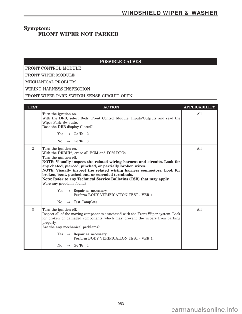
Symptom:
FRONT WIPER NOT PARKED
POSSIBLE CAUSES
FRONT CONTROL MODULE
FRONT WIPER MODULE
MECHANICAL PROBLEM
WIRING HARNESS INSPECTION
FRONT WIPER PARK SWITCH SENSE CIRCUIT OPEN
TEST ACTION APPLICABILITY
1 Turn the ignition on.
With the DRB, select Body, Front Control Module, Inputs/Outputs and read the
Wiper Park Sw state.
Does the DRB display Closed?All
Ye s®Go To 2
No®Go To 3
2 Turn the ignition on.
With the DRBIIIt, erase all BCM and FCM DTCs.
Turn the ignition off.
NOTE: Visually inspect the related wiring harness and circuits. Look for
any chafed, pierced, pinched, or partially broken wires.
NOTE: Visually inspect the related wiring harness connectors. Look for
broken, bent, pushed out, or corroded terminals.
Note: Refer to any Technical Service Bulletins (TSB) that may apply.
Were any problems found?All
Ye s®Repair as necessary.
Perform BODY VERIFICATION TEST - VER 1.
No®Test Complete.
3 Turn the ignition off.
Inspect all of the moving components associated with the Front Wiper system. Look
for broken or damaged components which may prevent the wipers from parking
properly.
Are the any mechanical problems?All
Ye s®Repair as necessary.
Perform BODY VERIFICATION TEST - VER 1.
No®Go To 4
963
WINDSHIELD WIPER & WASHER
Page 994 of 4284
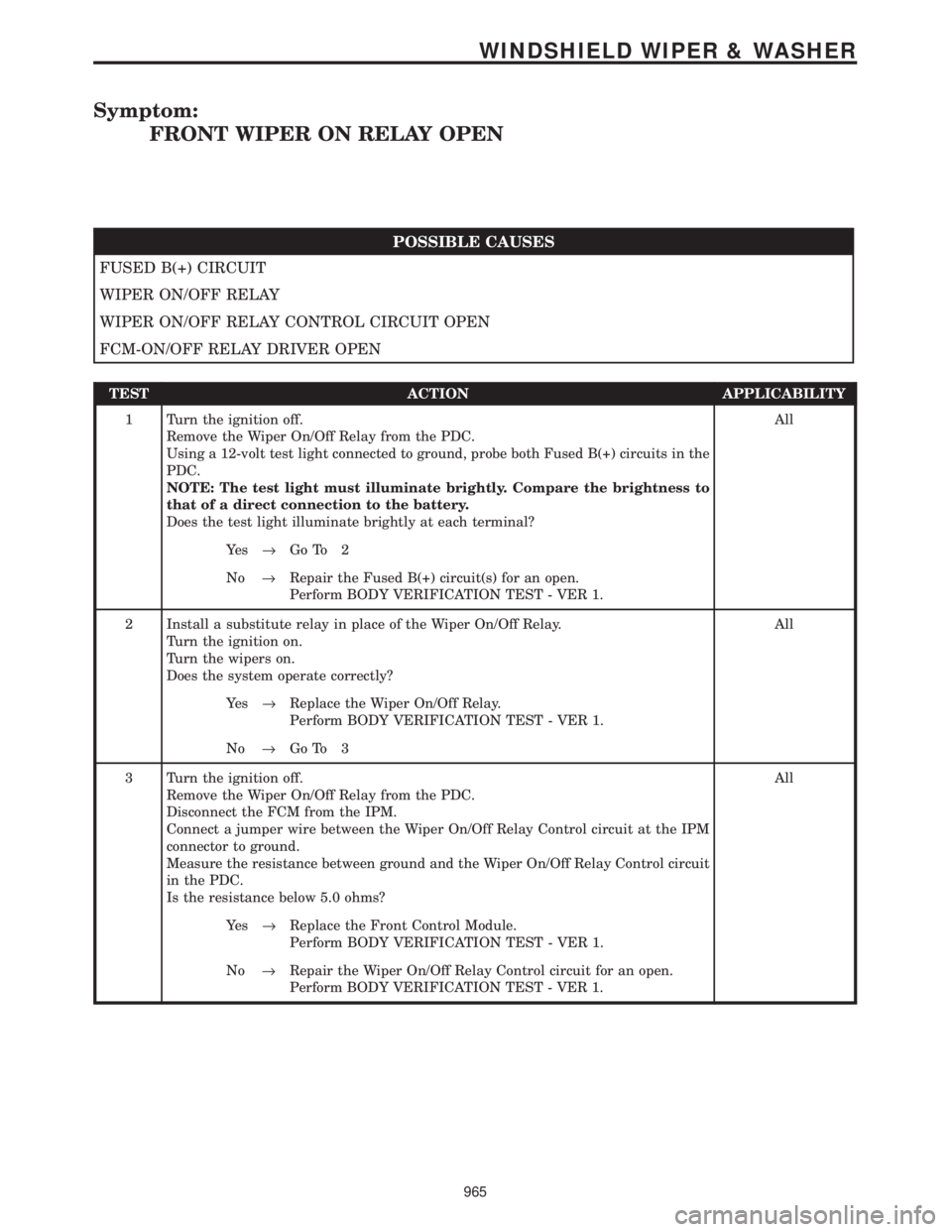
Symptom:
FRONT WIPER ON RELAY OPEN
POSSIBLE CAUSES
FUSED B(+) CIRCUIT
WIPER ON/OFF RELAY
WIPER ON/OFF RELAY CONTROL CIRCUIT OPEN
FCM-ON/OFF RELAY DRIVER OPEN
TEST ACTION APPLICABILITY
1 Turn the ignition off.
Remove the Wiper On/Off Relay from the PDC.
Using a 12-volt test light connected to ground, probe both Fused B(+) circuits in the
PDC.
NOTE: The test light must illuminate brightly. Compare the brightness to
that of a direct connection to the battery.
Does the test light illuminate brightly at each terminal?All
Ye s®Go To 2
No®Repair the Fused B(+) circuit(s) for an open.
Perform BODY VERIFICATION TEST - VER 1.
2 Install a substitute relay in place of the Wiper On/Off Relay.
Turn the ignition on.
Turn the wipers on.
Does the system operate correctly?All
Ye s®Replace the Wiper On/Off Relay.
Perform BODY VERIFICATION TEST - VER 1.
No®Go To 3
3 Turn the ignition off.
Remove the Wiper On/Off Relay from the PDC.
Disconnect the FCM from the IPM.
Connect a jumper wire between the Wiper On/Off Relay Control circuit at the IPM
connector to ground.
Measure the resistance between ground and the Wiper On/Off Relay Control circuit
in the PDC.
Is the resistance below 5.0 ohms?All
Ye s®Replace the Front Control Module.
Perform BODY VERIFICATION TEST - VER 1.
No®Repair the Wiper On/Off Relay Control circuit for an open.
Perform BODY VERIFICATION TEST - VER 1.
965
WINDSHIELD WIPER & WASHER
Page 995 of 4284
Symptom:
FRONT WIPER ON RELAY SHORT TO BATT
POSSIBLE CAUSES
WIPER ON/OFF RELAY
WIPER ON/OFF RELAY CONTROL CIRCUIT SHORTED TO VOLTAGE
FCM
TEST ACTION APPLICABILITY
1 Turn the ignition off.
Remove the Wiper On/Off Relay from the PDC.
Disconnect the FCM from the IPM.
Turn the ignition on.
Measure the voltage of the Wiper On/Off Relay Control circuit at the PDC connector.
Is the voltage above 1.0 volt?All
Ye s®Repair the Wiper On/Off Relay Control circuit for a short to
voltage.
Perform BODY VERIFICATION TEST - VER 1.
No®Go To 2
2 Install a substitute relay in place of the Wiper On/Off Relay.
Turn the ignition on.
Turn the wipers on.
Does the system operate correctly?All
Ye s®Replace the Wiper On/Off Relay.
Perform BODY VERIFICATION TEST - VER 1.
No®Replace the Front Control Module.
Perform BODY VERIFICATION TEST - VER 1.
966
WINDSHIELD WIPER & WASHER
Page 996 of 4284
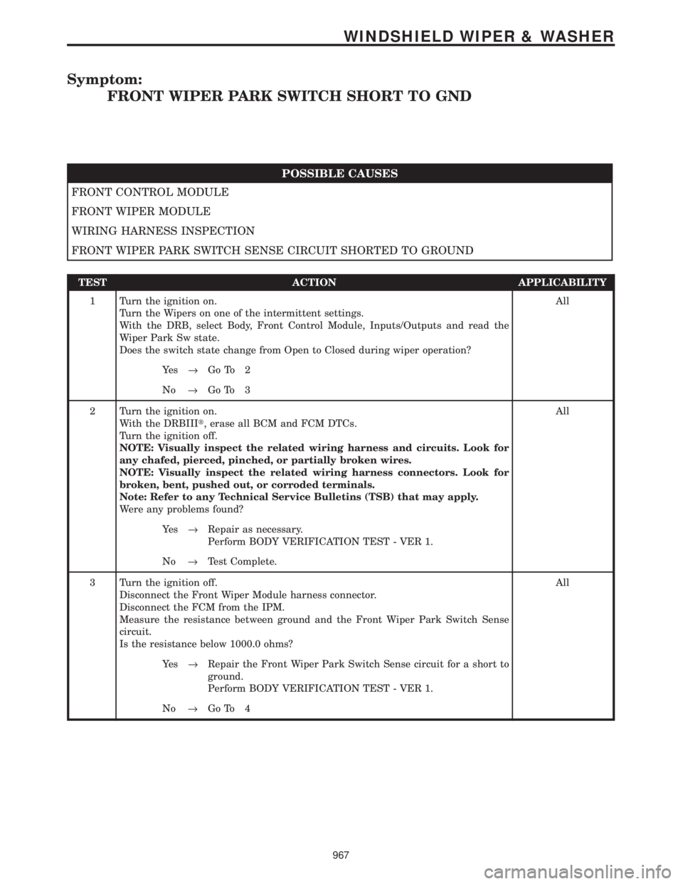
Symptom:
FRONT WIPER PARK SWITCH SHORT TO GND
POSSIBLE CAUSES
FRONT CONTROL MODULE
FRONT WIPER MODULE
WIRING HARNESS INSPECTION
FRONT WIPER PARK SWITCH SENSE CIRCUIT SHORTED TO GROUND
TEST ACTION APPLICABILITY
1 Turn the ignition on.
Turn the Wipers on one of the intermittent settings.
With the DRB, select Body, Front Control Module, Inputs/Outputs and read the
Wiper Park Sw state.
Does the switch state change from Open to Closed during wiper operation?All
Ye s®Go To 2
No®Go To 3
2 Turn the ignition on.
With the DRBIIIt, erase all BCM and FCM DTCs.
Turn the ignition off.
NOTE: Visually inspect the related wiring harness and circuits. Look for
any chafed, pierced, pinched, or partially broken wires.
NOTE: Visually inspect the related wiring harness connectors. Look for
broken, bent, pushed out, or corroded terminals.
Note: Refer to any Technical Service Bulletins (TSB) that may apply.
Were any problems found?All
Ye s®Repair as necessary.
Perform BODY VERIFICATION TEST - VER 1.
No®Test Complete.
3 Turn the ignition off.
Disconnect the Front Wiper Module harness connector.
Disconnect the FCM from the IPM.
Measure the resistance between ground and the Front Wiper Park Switch Sense
circuit.
Is the resistance below 1000.0 ohms?All
Ye s®Repair the Front Wiper Park Switch Sense circuit for a short to
ground.
Perform BODY VERIFICATION TEST - VER 1.
No®Go To 4
967
WINDSHIELD WIPER & WASHER
Page 997 of 4284
TEST ACTION APPLICABILITY
4 Turn the ignition on.
Turn the front wipers to an intermittent setting.
Using a 12-volt test light connected to 12-volts, back probe the Front Wiper Park
Switch Sense circuit at the Front Wiper Module harness connector.
NOTE: The test light should illuminate when the wipers are parked, then
turn off when the wipers move off of the parked position.
Does the test light turn on and off properly?All
Ye s®Replace the Front Control Module.
Perform BODY VERIFICATION TEST - VER 1.
No®Replace the Front Wiper Module.
Perform BODY VERIFICATION TEST - VER 1.
968
WINDSHIELD WIPER & WASHER
FRONT WIPER PARK SWITCH SHORT TO GND ÐContinued
Page 1731 of 4284
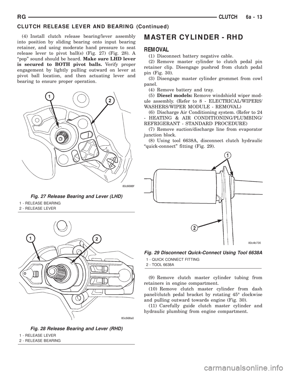
(4) Install clutch release bearing/lever assembly
into position by sliding bearing onto input bearing
retainer, and using moderate hand pressure to seat
release lever to pivot ball(s) (Fig. 27) (Fig. 28). A
ªpopº sound should be heard.Make sure LHD lever
is secured to BOTH pivot balls.Verify proper
engagement by lightly pulling outward on lever at
pivot ball location, and then actuating lever and
bearing to ensure proper operation.MASTER CYLINDER - RHD
REMOVAL
(1) Disconnect battery negative cable.
(2) Remove master cylinder to clutch pedal pin
retainer clip. Disengage pushrod from clutch pedal
pin (Fig. 30).
(3) Disengage master cylinder grommet from cowl
panel.
(4) Remove battery and tray.
(5)Diesel models:Remove windshield wiper mod-
ule assembly. (Refer to 8 - ELECTRICAL/WIPERS/
WASHERS/WIPER MODULE - REMOVAL)
(6) Discharge Air Conditioning system. (Refer to 24
- HEATING & AIR CONDITIONING/PLUMBING/
REFRIGERANT - STANDARD PROCEDURE)
(7) Remove suction/discharge line from evaporator
junction block.
(8) Using tool 6638A, disconnect clutch hydraulic
ªquick-connectº fitting (Fig. 29).
(9) Remove clutch master cylinder tubing from
retainers in engine compartment.
(10) Remove clutch master cylinder from dash
panel/clutch pedal bracket by rotating 45É clockwise
and pulling outward towards engine (Fig. 30).
(11) Carefully guide clutch master cylinder and
hydraulic plumbing from engine compartment.
Fig. 27 Release Bearing and Lever (LHD)
1 - RELEASE BEARING
2 - RELEASE LEVER
Fig. 28 Release Bearing and Lever (RHD)
1 - RELEASE LEVER
2 - RELEASE BEARING
Fig. 29 Disconnect Quick-Connect Using Tool 6638A
1 - QUICK CONNECT FITTING
2 - TOOL 6638A
RGCLUTCH6a-13
CLUTCH RELEASE LEVER AND BEARING (Continued)