2001 CHRYSLER VOYAGER windshield wipers
[x] Cancel search: windshield wipersPage 2082 of 4284
INSTALLATION
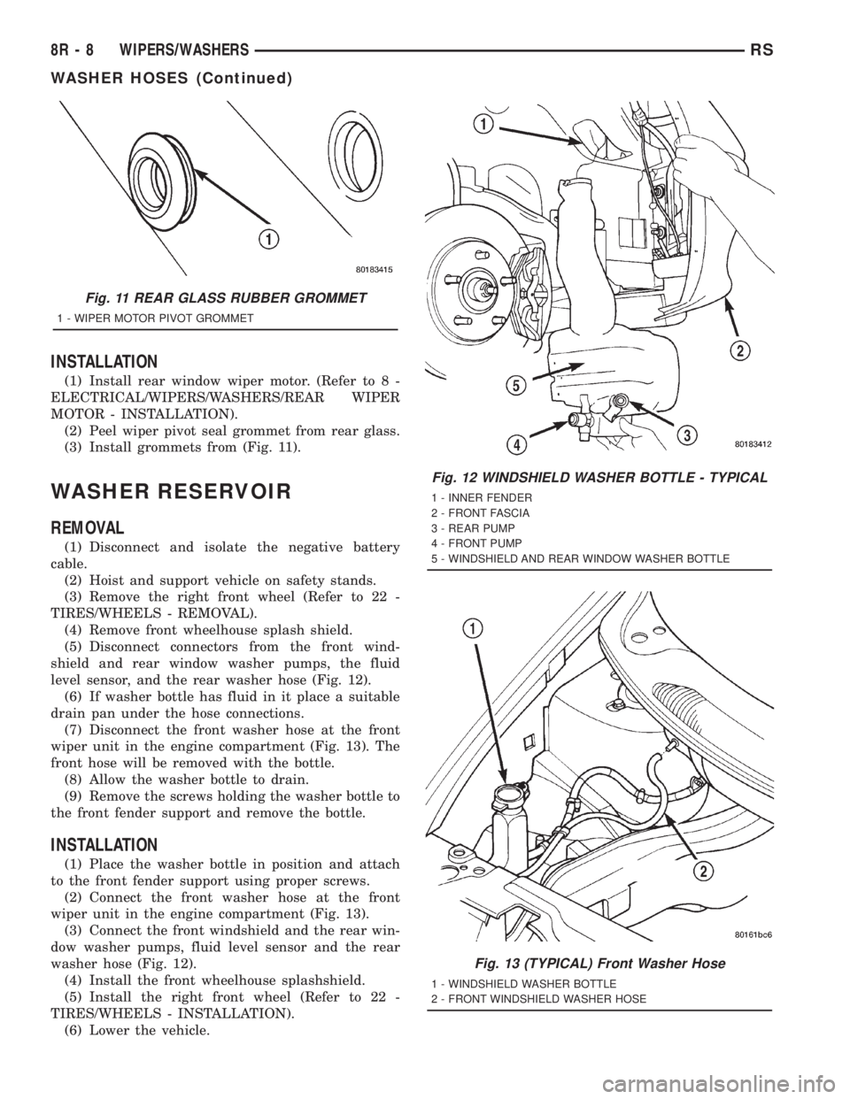
(1) Install rear window wiper motor. (Refer to 8 -
ELECTRICAL/WIPERS/WASHERS/REAR WIPER
MOTOR - INSTALLATION).
(2) Peel wiper pivot seal grommet from rear glass.
(3) Install grommets from (Fig. 11).
WASHER RESERVOIR
REMOVAL
(1) Disconnect and isolate the negative battery
cable.
(2) Hoist and support vehicle on safety stands.
(3) Remove the right front wheel (Refer to 22 -
TIRES/WHEELS - REMOVAL).
(4) Remove front wheelhouse splash shield.
(5) Disconnect connectors from the front wind-
shield and rear window washer pumps, the fluid
level sensor, and the rear washer hose (Fig. 12).
(6) If washer bottle has fluid in it place a suitable
drain pan under the hose connections.
(7) Disconnect the front washer hose at the front
wiper unit in the engine compartment (Fig. 13). The
front hose will be removed with the bottle.
(8) Allow the washer bottle to drain.
(9) Remove the screws holding the washer bottle to
the front fender support and remove the bottle.
INSTALLATION
(1) Place the washer bottle in position and attach
to the front fender support using proper screws.
(2) Connect the front washer hose at the front
wiper unit in the engine compartment (Fig. 13).
(3) Connect the front windshield and the rear win-
dow washer pumps, fluid level sensor and the rear
washer hose (Fig. 12).
(4) Install the front wheelhouse splashshield.
(5) Install the right front wheel (Refer to 22 -
TIRES/WHEELS - INSTALLATION).
(6) Lower the vehicle.
Fig. 11 REAR GLASS RUBBER GROMMET
1 - WIPER MOTOR PIVOT GROMMET
Fig. 12 WINDSHIELD WASHER BOTTLE - TYPICAL
1 - INNER FENDER
2 - FRONT FASCIA
3 - REAR PUMP
4 - FRONT PUMP
5 - WINDSHIELD AND REAR WINDOW WASHER BOTTLE
Fig. 13 (TYPICAL) Front Washer Hose
1 - WINDSHIELD WASHER BOTTLE
2 - FRONT WINDSHIELD WASHER HOSE
8R - 8 WIPERS/WASHERSRS
WASHER HOSES (Continued)
Page 2083 of 4284
WIPER BLADES
REMOVAL
(1) Lift the wiper arm away from the glass.
(2) Disengage the release tab holding the wiper
blade to the wiper arm and remove the wiper blade
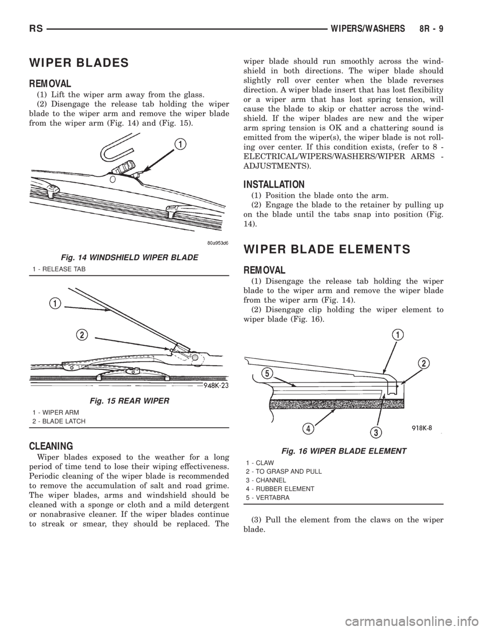
from the wiper arm (Fig. 14) and (Fig. 15).
CLEANING
Wiper blades exposed to the weather for a long
period of time tend to lose their wiping effectiveness.
Periodic cleaning of the wiper blade is recommended
to remove the accumulation of salt and road grime.
The wiper blades, arms and windshield should be
cleaned with a sponge or cloth and a mild detergent
or nonabrasive cleaner. If the wiper blades continue
to streak or smear, they should be replaced. Thewiper blade should run smoothly across the wind-
shield in both directions. The wiper blade should
slightly roll over center when the blade reverses
direction. A wiper blade insert that has lost flexibility
or a wiper arm that has lost spring tension, will
cause the blade to skip or chatter across the wind-
shield. If the wiper blades are new and the wiper
arm spring tension is OK and a chattering sound is
emitted from the wiper(s), the wiper blade is not roll-
ing over center. If this condition exists, (refer to 8 -
ELECTRICAL/WIPERS/WASHERS/WIPER ARMS -
ADJUSTMENTS).
INSTALLATION
(1) Position the blade onto the arm.
(2) Engage the blade to the retainer by pulling up
on the blade until the tabs snap into position (Fig.
14).
WIPER BLADE ELEMENTS
REMOVAL
(1) Disengage the release tab holding the wiper
blade to the wiper arm and remove the wiper blade
from the wiper arm (Fig. 14).
(2) Disengage clip holding the wiper element to
wiper blade (Fig. 16).
(3) Pull the element from the claws on the wiper
blade.
Fig. 14 WINDSHIELD WIPER BLADE
1 - RELEASE TAB
Fig. 15 REAR WIPER
1 - WIPER ARM
2 - BLADE LATCH
Fig. 16 WIPER BLADE ELEMENT
1 - CLAW
2 - TO GRASP AND PULL
3 - CHANNEL
4 - RUBBER ELEMENT
5 - VERTABRA
RSWIPERS/WASHERS8R-9
Page 2084 of 4284
INSTALLATION
(1) Insert the element vertebra (Fig. 16) into claw
at the open end of the wiper blade and through each
claw location along the blade.
(2) Engage clip to hold wiper element to wiper
blade.
(3) Test wiper effectiveness using washer mode
and align if necessary.
WIPER LINKAGE
REMOVAL
(1) Remove the windshield wiper unit from vehicle.
(Refer to 8 - ELECTRICAL/WIPERS/WASHERS/
WIPER MODULE - REMOVAL).
(2) Place the wiper unit on a suitable work sur-
face.
(3) Remove nuts holding the cowl cover brackets to
the wiper unit.
(4) Remove cowl cover brackets from the wiper
unit.
(5) Remove nuts holding linkage and motor mount
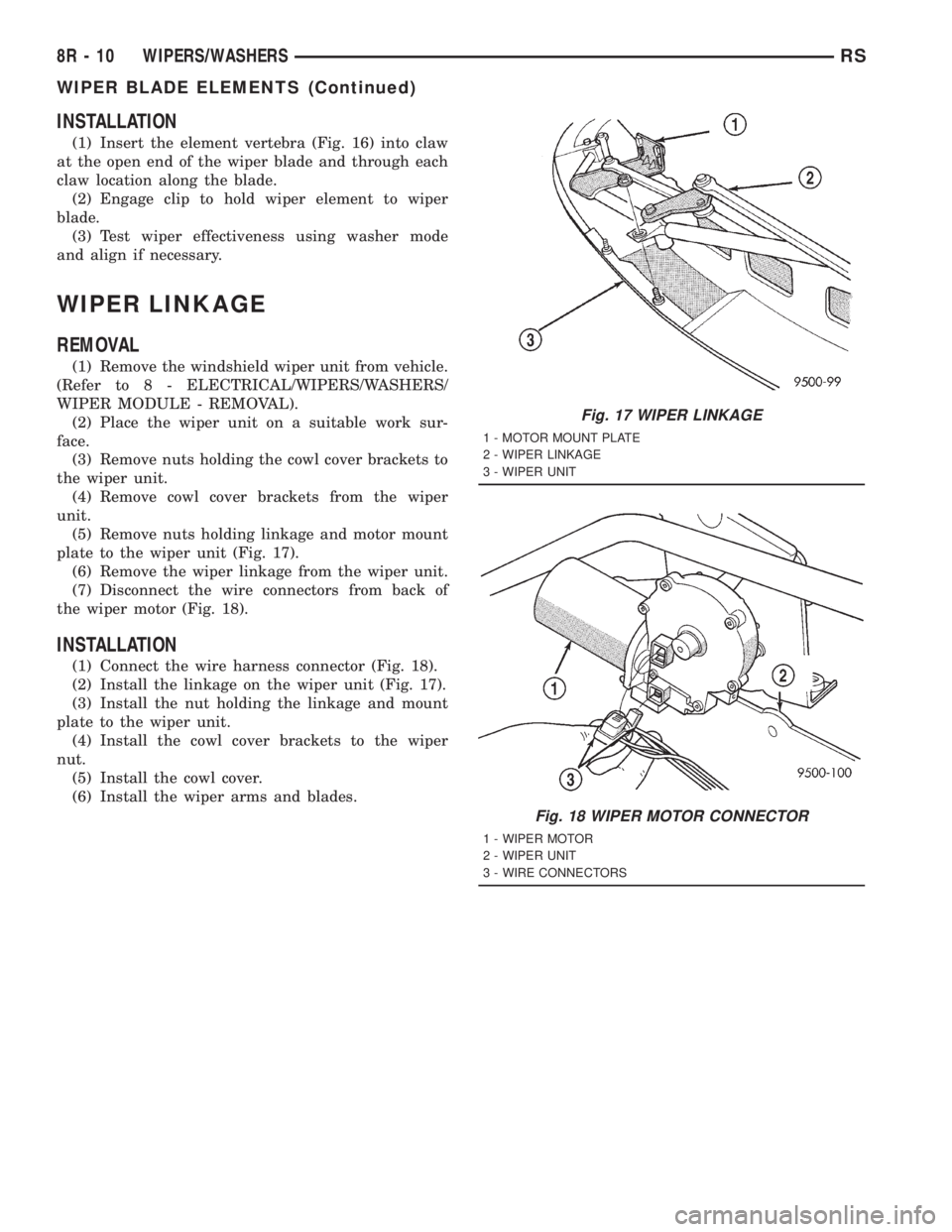
plate to the wiper unit (Fig. 17).
(6) Remove the wiper linkage from the wiper unit.
(7) Disconnect the wire connectors from back of
the wiper motor (Fig. 18).
INSTALLATION
(1) Connect the wire harness connector (Fig. 18).
(2) Install the linkage on the wiper unit (Fig. 17).
(3) Install the nut holding the linkage and mount
plate to the wiper unit.
(4) Install the cowl cover brackets to the wiper
nut.
(5) Install the cowl cover.
(6) Install the wiper arms and blades.
Fig. 18 WIPER MOTOR CONNECTOR
1 - WIPER MOTOR
2 - WIPER UNIT
3 - WIRE CONNECTORS
Fig. 17 WIPER LINKAGE
1 - MOTOR MOUNT PLATE
2 - WIPER LINKAGE
3 - WIPER UNIT
8R - 10 WIPERS/WASHERSRS
WIPER BLADE ELEMENTS (Continued)
Page 3570 of 4284
COWL GRILLE
REMOVAL
(1) Remove wiper arms. (Refer to 8 - ELECTRI-
CAL/WIPERS/WASHERS/WIPER ARMS -
REMOVAL)
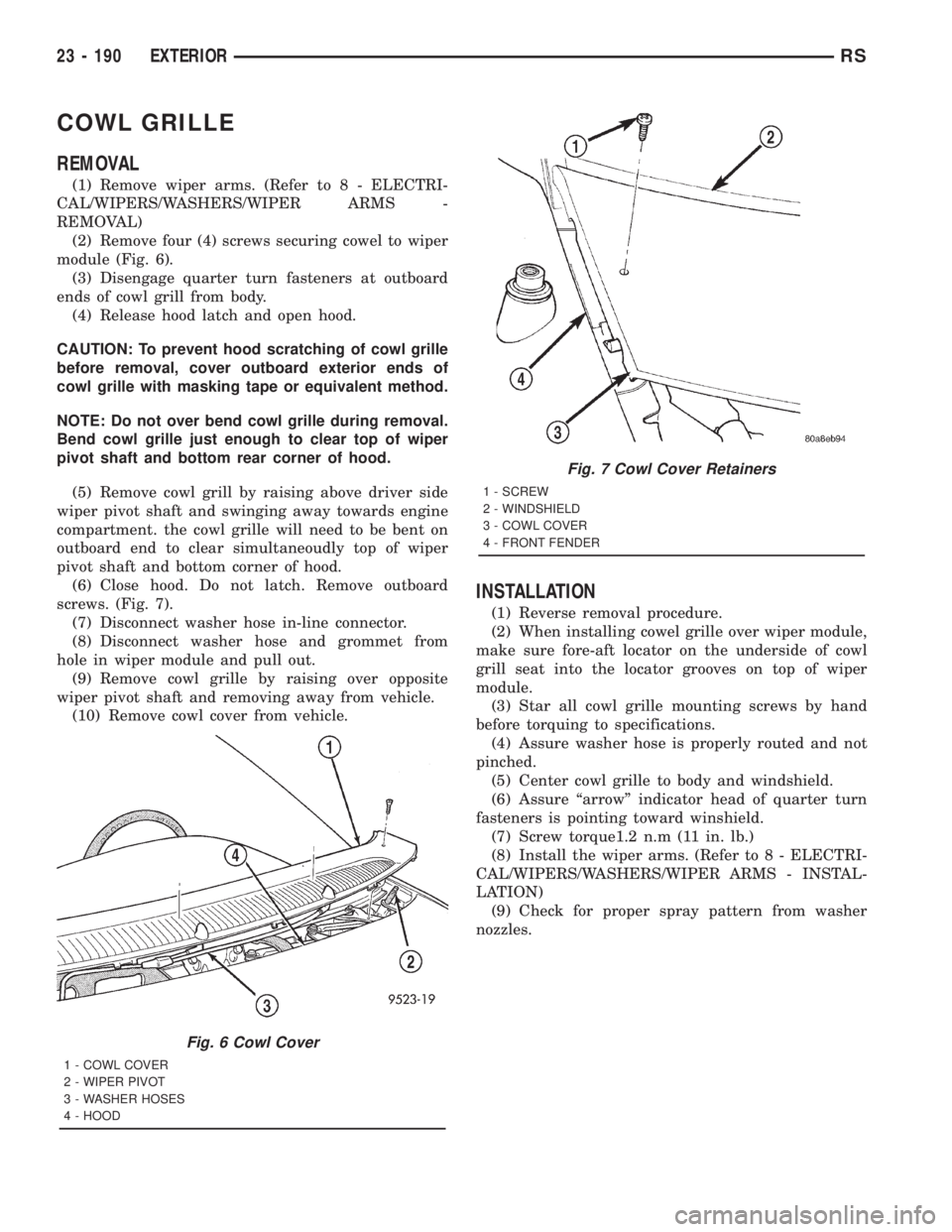
(2) Remove four (4) screws securing cowel to wiper
module (Fig. 6).
(3) Disengage quarter turn fasteners at outboard
ends of cowl grill from body.
(4) Release hood latch and open hood.
CAUTION: To prevent hood scratching of cowl grille
before removal, cover outboard exterior ends of
cowl grille with masking tape or equivalent method.
NOTE: Do not over bend cowl grille during removal.
Bend cowl grille just enough to clear top of wiper
pivot shaft and bottom rear corner of hood.
(5) Remove cowl grill by raising above driver side
wiper pivot shaft and swinging away towards engine
compartment. the cowl grille will need to be bent on
outboard end to clear simultaneoudly top of wiper
pivot shaft and bottom corner of hood.
(6) Close hood. Do not latch. Remove outboard
screws. (Fig. 7).
(7) Disconnect washer hose in-line connector.
(8) Disconnect washer hose and grommet from
hole in wiper module and pull out.
(9) Remove cowl grille by raising over opposite
wiper pivot shaft and removing away from vehicle.
(10) Remove cowl cover from vehicle.
INSTALLATION
(1) Reverse removal procedure.
(2) When installing cowel grille over wiper module,
make sure fore-aft locator on the underside of cowl
grill seat into the locator grooves on top of wiper
module.
(3) Star all cowl grille mounting screws by hand
before torquing to specifications.
(4) Assure washer hose is properly routed and not
pinched.
(5) Center cowl grille to body and windshield.
(6) Assure ªarrowº indicator head of quarter turn
fasteners is pointing toward winshield.
(7) Screw torque1.2 n.m (11 in. lb.)
(8) Install the wiper arms. (Refer to 8 - ELECTRI-
CAL/WIPERS/WASHERS/WIPER ARMS - INSTAL-
LATION)
(9) Check for proper spray pattern from washer
nozzles.
Fig. 6 Cowl Cover
1 - COWL COVER
2 - WIPER PIVOT
3 - WASHER HOSES
4 - HOOD
Fig. 7 Cowl Cover Retainers
1 - SCREW
2 - WINDSHIELD
3 - COWL COVER
4 - FRONT FENDER
23 - 190 EXTERIORRS
Page 3625 of 4284
(15) Clean access urethane from exterior with
Moparž Super Kleen or equivalent.
(16) Apply 150 mm (6 in.) lengths of 50 mm (2 in.)
masking tape spaced 250 mm (10 in.) apart to hold
molding in place until urethane cures.
(17) Engage wire connectors to windshield
defroster grid.
(18) Install A-pillar trim panels.
(19) Install cowl cover and wipers.
(20) Install inside rear view mirror.
(21) After urethane has cured, remove tape strips
and water test windshield to verify repair.SLIDING DOOR GLASS
REMOVAL
The temperature of the vehicle should be at least
21É C (70É F) before removing the stationary quarter/
sliding door glass. Butyl sealer becomes more pliable
at high temperatures.
(1) Remove interior trim as necessary to gain
access attaching locations on back of glass.
(2) Remove nuts holding stationary glass to fence.
(3) Using razor knife, cut butyl sealer holding
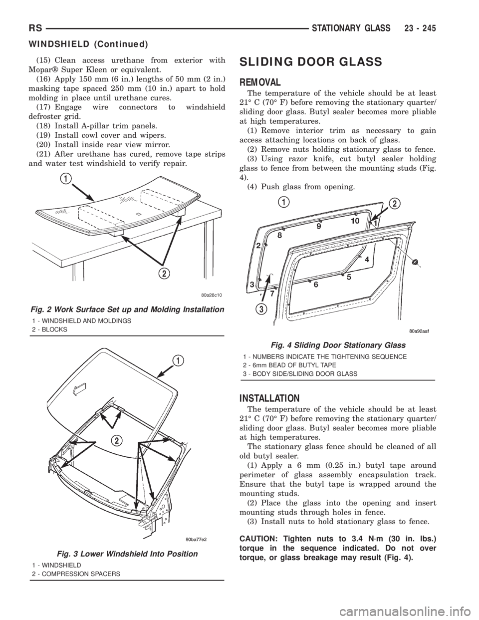
glass to fence from between the mounting studs (Fig.
4).
(4) Push glass from opening.
INSTALLATION
The temperature of the vehicle should be at least
21É C (70É F) before removing the stationary quarter/
sliding door glass. Butyl sealer becomes more pliable
at high temperatures.
The stationary glass fence should be cleaned of all
old butyl sealer.
(1) Applya6mm(0.25 in.) butyl tape around
perimeter of glass assembly encapsulation track.
Ensure that the butyl tape is wrapped around the
mounting studs.
(2) Place the glass into the opening and insert
mounting studs through holes in fence.
(3) Install nuts to hold stationary glass to fence.
CAUTION: Tighten nuts to 3.4 N´m (30 in. lbs.)
torque in the sequence indicated. Do not over
torque, or glass breakage may result (Fig. 4).
Fig. 2 Work Surface Set up and Molding Installation
1 - WINDSHIELD AND MOLDINGS
2 - BLOCKS
Fig. 3 Lower Windshield Into Position
1 - WINDSHIELD
2 - COMPRESSION SPACERS
Fig. 4 Sliding Door Stationary Glass
1 - NUMBERS INDICATE THE TIGHTENING SEQUENCE
2 - 6mm BEAD OF BUTYL TAPE
3 - BODY SIDE/SLIDING DOOR GLASS
RSSTATIONARY GLASS23 - 245
WINDSHIELD (Continued)
Page 3654 of 4284
peratures it monitors. The heater-A/C control module
is connected to the sensor through a sensor ground
circuit and a sensor signal circuit. As the evaporator
temperature increases, the resistance of the sensor
decreases and the voltage monitored by the module
decreases. The module uses this monitored voltage
reading to an indication of the evaporator tempera-
ture. The heater-A/C control module is programmed
to respond to this input by sending electronic mes-
sages to the Powertrain Control Module (PCM) over
the Programmable Communications Interface (PCI)
data bus, and the PCM then cycles the air condition-
ing compressor clutch as necessary to optimize air
conditioning system performance and to protect the
system from evaporator freezing. The external loca-
tion of the sensor and the use of a push-in plastic
retainer allows the sensor to be removed or installed
from the expansion valve without disturbing the
refrigerant in the system. The evaporator tempera-
ture sensor is diagnosed using a DRBIIItscan tool.
Refer to the appropriate diagnostic information.
REMOVAL
(1) Disconnect and isolate the battery negative
cable.
(2) Remove the air cleaner housing from the right
side of the engine compartment.
(3) Remove the windshield wiper assembly from
the vehicle (Refer to 8 - ELECTRICAL/WIPERS/
WASHERS/WIPER MODULE - REMOVAL).
(4) Remove the temperature sensor attaching
screw from the expansion valve.
(5) Pull the evaporator temperature sensor away
from the expansion valve far enough to access the
red release ring on the wiring connector. Push the
red ring toward the connector to release lock and
remove the HVAC wire harness connector from the
temperature sensor.
(6) Remove the evaporator temperature sensor
from the engine compartment. Please note that any
grease removed with the old temperature sensor
must be replaced, failure to do so could result in poor
a/c performance.
INSTALLATION
(1) Position the evaporator temperature sensor
into the right rear corner of the engine compartment.
(2) Reconnect the HVAC wire harness connector
for the evaporator temperature sensor to the sensor
connector receptacle.
(3) Position the evaporator temperature sensor
onto the top of the expansion valve with the sensor
probe inserted into the well in the expansion valve
(Fig. 19).
(4) Install the temperature sensor retaining screw
and tighten.(5) Install the window wiper assembly to the vehi-
cle (REFER to 8 - ELECTRICAL/WIPERS/WASH-
ERS/WIPER MODULE - INSTALLATION).
(6) Reinstall the air cleaner housing into the right
side of the engine compartment.
(7) Reconnect the battery negative cable.
INFRARED TEMPERATURE
SENSOR
DESCRIPTION
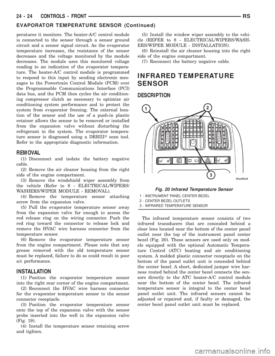
The infrared temperature sensor consists of two
infrared transducers that are concealed behind a
clear lens located near the bottom of the center panel
outlet near the top of the instrument panel center
bezel (Fig. 20). These sensors are used only on mod-
els equipped with the optional Automatic Tempera-
ture Control (ATC) heating and air conditioning
system. A molded plastic connector receptacle on the
bottom of the panel outlet unit is concealed behind
the center bezel. A short, dedicated jumper wire har-
ness routed behind the center bezel connects the sen-
sors directly to the ATC heater-A/C control module
near the bottom of the center bezel. The infrared
temperature sensor is integral to the center bezel
panel outlet unit. The infrared sensors cannot be
adjusted or repaired and, if faulty or damaged, the
center bezel panel outlet unit must be replaced.
Fig. 20 Infrared Temperature Sensor
1 - INSTRUMENT PANEL CENTER BEZEL
2 - CENTER BEZEL OUTLETS
3 - INFRARED TEMPERATURE SENSOR
24 - 24 CONTROLS - FRONTRS
EVAPORATOR TEMPERATURE SENSOR (Continued)