2001 CHRYSLER VOYAGER coolant level
[x] Cancel search: coolant levelPage 1223 of 4284
check the shared circuits for possible problems
before continuing (i.e. Sensor Grounds or 5-Volt
Supply circuits). Refer to the appropriate wiring
diagrams to identify shared circuits.
MASS AIR FLOW SENSOR SIGNAL VOLTAGE
TOO HIGH
MASS AIR FLOW SENSOR SIGNAL VOLTAGE
TOO LOW
MASS AIR FLOW SENSOR SUPPLY VOLTAGE
TOO HIGH OR LOW
MASS AIR FLOW SENSOR PLAUSIBILITY
MASS AIR FLOW SENSOR SIGNAL PLAUSI-
BILITY POSITIVE AREA
BAROMETRIC PRESSURE CIRCUIT SIGNAL
VOLTAGE TOO HIGH
BAROMETRIC PRESSURE CIRCUIT SIGNAL
VOLTAGE TOO LOW
INTAKE AIR TEMP SENSOR SIGNAL VOLT-
AGE TOO HIGH
INTAKE AIR TEMP SENSOR SIGNAL VOLT-
AGE TOO LOW
ENGINE COOLANT TEMP SENSOR SIGNAL
VOLTAGE TOO HIGH
ENGINE COOLANT TEMP SENSOR SIGNAL
VOLTAGE TOO LOW
FUEL PRESS SENSOR CIRCUIT MALF SIG-
NAL VOLTAGE TOO HIGH
FUEL PRESS SENSOR CIRCUIT MALF SIG-
NAL VOLTAGE TOO LOW
FUEL PRESS SENSOR CIRCUIT MALF SUP-
PLY VOLTAGE TOO HIGH OR LOW
OIL TEMP SENSOR CIRCUIT MALF SIGNAL
VOLTAGE TOO HIGH
OIL TEMP SENSOR CIRCUIT MALF SIGNAL
VOLTAGE TOO LOW
CYLINDER 1-INJECTOR CIRCUIT OVERCUR-
RENT HIGH SIDE
CYLINDER 1-INJECTOR CIRCUIT OVERCUR-
RENT LOW SIDE
CYLINDER 1-INJECTOR CIRCUIT LOAD
DROP
CYLINDER 1-INJECTOR CIRCUIT CURRENT
DECREASE
CYLINDER 2-INJECTOR CIRCUIT OVERCUR-
RENT HIGH SIDE
CYLINDER 2-INJECTOR CIRCUIT OVERCUR-
RENT LOW SIDE
CYLINDER 2-INJECTOR CIRCUIT LOAD
DROP
CYLINDER 2-INJECTOR CIRCUIT CURRENT
DECREASE
CYLINDER 3-INJECTOR CIRCUIT OVERCUR-
RENT HIGH SIDE
CYLINDER 3-INJECTOR CIRCUIT OVERCUR-
RENT LOW SIDE
CYLINDER 3-INJECTOR CIRCUIT LOAD
DROPCYLINDER 3-INJECTOR CIRCUIT CURRENT
DECREASE
CYLINDER 4-INJECTOR CIRCUIT OVERCUR-
RENT HIGH SIDE
CYLINDER 4-INJECTOR CIRCUIT OVERCUR-
RENT LOW SIDE
CYLINDER 4-INJECTOR CIRCUIT LOAD
DROP
CYLINDER 4-INJECTOR CIRCUIT CURRENT
DECREASE
BOOST PRESSURE SENSOR SIGNAL VOLT-
AGE TOO HIGH
BOOST PRESSURE SENSOR SIGNAL VOLT-
AGE TOO LOW
BOOST PRESSURE SENSOR SUPPLY VOLT-
AGE TOO HIGH OR LOW
BOOST PRESSURE SENSOR PLAUSIBILITY
CKP POSITION SENSOR CIRCUIT OVER-
SPEED RECOGNITION
CKP POSITION SENSOR CIRCUIT DYNAMIC
PLAUSIBILITY
CKP POSITION SENSOR CIRCUIT STATIC
PLAUSIBILITY
CMP POSITION SENSOR CIRCUIT CMP/CKP
SYNC FAILURE
CMP POSITION SENSOR CIRCUIT DYNAMIC
PLAUSIBILITY
CMP POSITION SENSOR CIRCUIT STATIC
PLAUSIBILITY
CMP POSITION SENSOR CIRCUIT SIGNAL
FREQUENCY TOO HIGH
CMP POSITION SENSOR CIRCUIT FUEL
SHUT-OFF ACTIVATED
GLOW PLUG CIRCUIT A SHORT CIRCUIT
GLOW PLUG CIRCUIT A OPEN CIRCUIT
EGR SOLENOID CIRCUIT OPEN CIRCUIT
EGR SOLENOID CIRCUIT SHORT CIRCUIT
EGR SOLENOID CIRCUIT IMPROPER FLOW
FAN 1 CONTROL CIRCUIT OPEN CIRCUIT
FAN 1 CONTROL CIRCUIT SHORT CIRCUIT
FAN 2 CONTROL CIRCUIT OPEN CIRCUIT
FAN 2 CONTROL CIRCUIT SHORT CIRCUIT
VEHICLE SPEED SENSOR SIGNAL VOLTAGE
TOO HIGH
VEHICLE SPEED SENSOR FREQUENCY TOO
HIGH
VEHICLE SPEED SENSOR HIGH LEVEL DU-
RATION
VEHICLE SPEED SENSOR PLAUSIBILITY
BATTERY TEMP SENSOR SIGNAL VOLTAGE
TOO HIGH
BATTERY TEMP SENSOR SIGNAL VOLTAGE
TOO LOW
OIL PRESS SENSOR CKT MALF PLAUSIBIL-
ITY
4
GENERAL INFORMATION
Page 1495 of 4284
LUBRICANTS AND GREASES
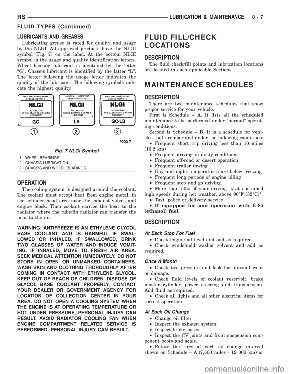
Lubricating grease is rated for quality and usage
by the NLGI. All approved products have the NLGI
symbol (Fig. 7) on the label. At the bottom NLGI
symbol is the usage and quality identification letters.
Wheel bearing lubricant is identified by the letter
ªGº. Chassis lubricant is identified by the latter ªLº.
The letter following the usage letter indicates the
quality of the lubricant. The following symbols indi-
cate the highest quality.
OPERATION
The cooling system is designed around the coolant.
The coolant must accept heat from engine metal, in
the cylinder head area near the exhaust valves and
engine block. Then coolant carries the heat to the
radiator where the tube/fin radiator can transfer the
heat to the air.
WARNING: ANTIFREEZE IS AN ETHYLENE GLYCOL
BASE COOLANT AND IS HARMFUL IF SWAL-
LOWED OR INHALED. IF SWALLOWED, DRINK
TWO GLASSES OF WATER AND INDUCE VOMIT-
ING. IF INHALED, MOVE TO FRESH AIR AREA.
SEEK MEDICAL ATTENTION IMMEDIATELY. DO NOT
STORE IN OPEN OR UNMARKED CONTAINERS.
WASH SKIN AND CLOTHING THOROUGHLY AFTER
COMING IN CONTACT WITH ETHYLENE GLYCOL.
KEEP OUT OF REACH OF CHILDREN. DISPOSE OF
GLYCOL BASE COOLANT PROPERLY, CONTACT
YOUR DEALER OR GOVERNMENT AGENCY FOR
LOCATION OF COLLECTION CENTER IN YOUR
AREA. DO NOT OPEN A COOLING SYSTEM WHEN
THE ENGINE IS AT OPERATING TEMPERATURE OR
HOT UNDER PRESSURE, PERSONAL INJURY CAN
RESULT. AVOID RADIATOR COOLING FAN WHEN
ENGINE COMPARTMENT RELATED SERVICE IS
PERFORMED, PERSONAL INJURY CAN RESULT.
FLUID FILL/CHECK
LOCATIONS
DESCRIPTION
The fluid check/fill points and lubrication locations
are located in each applicable Sections.
MAINTENANCE SCHEDULES
DESCRIPTION
There are two maintenance schedules that show
proper service for your vehicle.
First is Schedule ±A. It lists all the scheduled
maintenance to be performed under ªnormalº operat-
ing conditions.
Second is Schedule ±B. It is a schedule for vehi-
cles that are operated under the following conditions:
²Frequent short trip driving less than 10 miles
(16.2 km)
²Frequent driving in dusty conditions
²Frequent off-road or desert operation
²Frequent trailer towing
²Day and night temperatures are below freezing
²Frequent long periods of engine idling
²Frequent stop and go driving
²More than 50% of your driving is at sustained
high speeds during hot weather, above 90ÉF (32ÉC)*
²Taxi, police or delivery service
²If equipped for and operation with E-85
(ethanol) fuel.
DESCRIPTION
At Each Stop For Fuel
²Check engine oil level and add as required.
²Check windshield washer solvent and add as
required.
Once A Month
²Check tire pressure and look for unusual wear
or damage.
²Check fluid levels of coolant reservoir, brake
master cylinder, power steering and transmission.
Add fluid as required.
²Check all lights and all other electrical items for
correct operation.
At Each Oil Change
²Change oil filter
²Inspect the exhaust system.
²Inspect brake hoses.
²Inspect the CV joints and front suspension com-
ponent boots and seals.
²Rotate the tires at each oil change interval
shown on Schedule ± A (7,500 miles - 12 000 km) or
Fig. 7 NLGI Symbol
1 - WHEEL BEARINGS
2 - CHASSIS LUBRICATION
3 - CHASSIS AND WHEEL BEARINGS
RSLUBRICATION & MAINTENANCE0-7
FLUID TYPES (Continued)
Page 1496 of 4284
every other interval on Schedule ± B (6,000 miles -
10 000 km).
²Check the engine coolant level, hoses, and
clamps.
EMISSION CONTROL SYSTEM MAINTENANCE
The scheduled emission maintenance listed inbold
typeon the Maintenance Schedules, must be done at
the mileage specified to assure the continued proper
functioning of the emission control system. These,
and all other maintenance services included in this
manual, should be done to provide the best vehicle
performance and reliability. More frequent mainte-
nance may be needed for vehicles in severe operating
conditions such as dusty areas and very short trip
driving.
DESCRIPTION - MAINTENANCE SCHEDULES
SCHEDULE±A±CHRYSLER TOWN AND
COUNTRY VEHICLES
7,500 Miles (12 000 km) or at 6 months
²Change the engine oil.
²Replace the engine oil filter.
15,000 Miles (24 000 km) or at 12 months
²Change the engine oil.
²Replace the engine oil filter.
22,500 Miles (36 000 km) or at 18 months
²Change the engine oil.
²Replace the engine oil filter.
²Inspect the brake linings.
30,000 Miles (48 000 km) or at 24 months
²Change the engine oil.
²Replace the engine oil filter.
²Replace the engine air cleaner element (fil-
ter).
²Inspect the tie rod ends and boot seals.
37,500 Miles (60 000 km) or at 30 months
²Change the engine oil.
²Replace the engine oil filter.
45,000 Miles (72 000 km) or at 36 months
²Change the engine oil.
²Replace the engine oil filter.
²Inspect the brake linings.
52,500 Miles (84 000 km) or at 42 months
²Change the engine oil.
²Replace the engine oil filter.
60,000 Miles (96 000 km) or at 48 months
²Change the engine oil.
²Replace the engine oil filter.
²Replace the engine air cleaner element (fil-
ter).
²Check the PCV valve and replace, if neces-
sary.*
²Inspect the serpentine drive belt, replace if nec-
essary.
²Inspect the tie rod ends and boot seals.
67,500 Miles (108 000 km) or at 54 months
²Change the engine oil.
²Replace the engine oil filter.
²Inspect the brake linings.
75,000 Miles (120 000 km) or at 60 months
²Change the engine oil.
²Replace the engine oil filter.
²Inspect the serpentine drive belt and replace if
necessary. This maintenance is not required if the
belt was previously replaced.
²Flush and replace engine coolant at 60 months.
82,500 Miles (132 000 km) or at 66 months
²Change the engine oil.
²Replace the engine oil filter.
90,000 Miles (144 000 km) or at 72 months
²Change the engine oil.
²Replace the engine oil filter.
²Replace the engine air cleaner element (fil-
ter).
²Check the PCV valve and replace, if neces-
sary. Not required if previously changed.*
²Inspect the serpentine drive belt, replace if nec-
essary. This maintenance is not required if the belt
was previously replaced.
²Inspect the tie rod ends and boot seals.
²Inspect the brake linings.
97,500 Miles (156 000 km) or at 78 months
²Change the engine oil.
²Replace the engine oil filter.
100,000 Miles (160,000 km)
²Replace the spark plugs.
²Replace the ignition cables.
²Flush and replace engine coolant at 60 months
or 100,000 miles (160,000 km).
105,000 Miles (168 000 km) or at 84 months
²Change the engine oil.
²Replace the engine oil filter.
²Inspect the serpentine drive belt and replace if
necessary. This maintenance is not required if the
belt was previously replaced.
0 - 8 LUBRICATION & MAINTENANCERS
MAINTENANCE SCHEDULES (Continued)
Page 1509 of 4284
LUBRICANTS AND GREASES
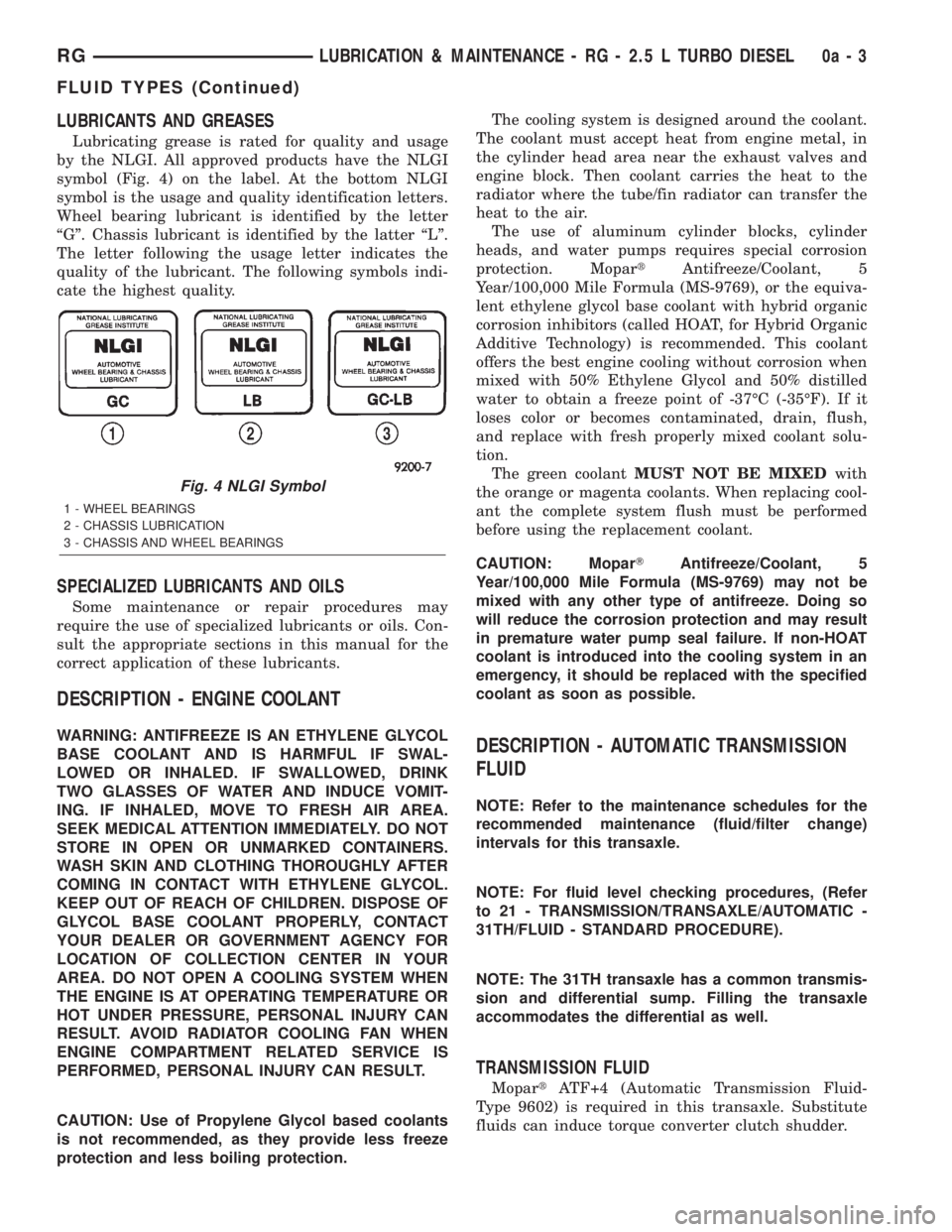
Lubricating grease is rated for quality and usage
by the NLGI. All approved products have the NLGI
symbol (Fig. 4) on the label. At the bottom NLGI
symbol is the usage and quality identification letters.
Wheel bearing lubricant is identified by the letter
ªGº. Chassis lubricant is identified by the latter ªLº.
The letter following the usage letter indicates the
quality of the lubricant. The following symbols indi-
cate the highest quality.
SPECIALIZED LUBRICANTS AND OILS
Some maintenance or repair procedures may
require the use of specialized lubricants or oils. Con-
sult the appropriate sections in this manual for the
correct application of these lubricants.
DESCRIPTION - ENGINE COOLANT
WARNING: ANTIFREEZE IS AN ETHYLENE GLYCOL
BASE COOLANT AND IS HARMFUL IF SWAL-
LOWED OR INHALED. IF SWALLOWED, DRINK
TWO GLASSES OF WATER AND INDUCE VOMIT-
ING. IF INHALED, MOVE TO FRESH AIR AREA.
SEEK MEDICAL ATTENTION IMMEDIATELY. DO NOT
STORE IN OPEN OR UNMARKED CONTAINERS.
WASH SKIN AND CLOTHING THOROUGHLY AFTER
COMING IN CONTACT WITH ETHYLENE GLYCOL.
KEEP OUT OF REACH OF CHILDREN. DISPOSE OF
GLYCOL BASE COOLANT PROPERLY, CONTACT
YOUR DEALER OR GOVERNMENT AGENCY FOR
LOCATION OF COLLECTION CENTER IN YOUR
AREA. DO NOT OPEN A COOLING SYSTEM WHEN
THE ENGINE IS AT OPERATING TEMPERATURE OR
HOT UNDER PRESSURE, PERSONAL INJURY CAN
RESULT. AVOID RADIATOR COOLING FAN WHEN
ENGINE COMPARTMENT RELATED SERVICE IS
PERFORMED, PERSONAL INJURY CAN RESULT.
CAUTION: Use of Propylene Glycol based coolants
is not recommended, as they provide less freeze
protection and less boiling protection.The cooling system is designed around the coolant.
The coolant must accept heat from engine metal, in
the cylinder head area near the exhaust valves and
engine block. Then coolant carries the heat to the
radiator where the tube/fin radiator can transfer the
heat to the air.
The use of aluminum cylinder blocks, cylinder
heads, and water pumps requires special corrosion
protection. MopartAntifreeze/Coolant, 5
Year/100,000 Mile Formula (MS-9769), or the equiva-
lent ethylene glycol base coolant with hybrid organic
corrosion inhibitors (called HOAT, for Hybrid Organic
Additive Technology) is recommended. This coolant
offers the best engine cooling without corrosion when
mixed with 50% Ethylene Glycol and 50% distilled
water to obtain a freeze point of -37ÉC (-35ÉF). If it
loses color or becomes contaminated, drain, flush,
and replace with fresh properly mixed coolant solu-
tion.
The green coolantMUST NOT BE MIXEDwith
the orange or magenta coolants. When replacing cool-
ant the complete system flush must be performed
before using the replacement coolant.
CAUTION: MoparTAntifreeze/Coolant, 5
Year/100,000 Mile Formula (MS-9769) may not be
mixed with any other type of antifreeze. Doing so
will reduce the corrosion protection and may result
in premature water pump seal failure. If non-HOAT
coolant is introduced into the cooling system in an
emergency, it should be replaced with the specified
coolant as soon as possible.DESCRIPTION - AUTOMATIC TRANSMISSION
FLUID
NOTE: Refer to the maintenance schedules for the
recommended maintenance (fluid/filter change)
intervals for this transaxle.
NOTE: For fluid level checking procedures, (Refer
to 21 - TRANSMISSION/TRANSAXLE/AUTOMATIC -
31TH/FLUID - STANDARD PROCEDURE).
NOTE: The 31TH transaxle has a common transmis-
sion and differential sump. Filling the transaxle
accommodates the differential as well.
TRANSMISSION FLUID
MopartATF+4 (Automatic Transmission Fluid-
Type 9602) is required in this transaxle. Substitute
fluids can induce torque converter clutch shudder.
Fig. 4 NLGI Symbol
1 - WHEEL BEARINGS
2 - CHASSIS LUBRICATION
3 - CHASSIS AND WHEEL BEARINGS
RGLUBRICATION & MAINTENANCE - RG - 2.5 L TURBO DIESEL0a-3
FLUID TYPES (Continued)
Page 1511 of 4284
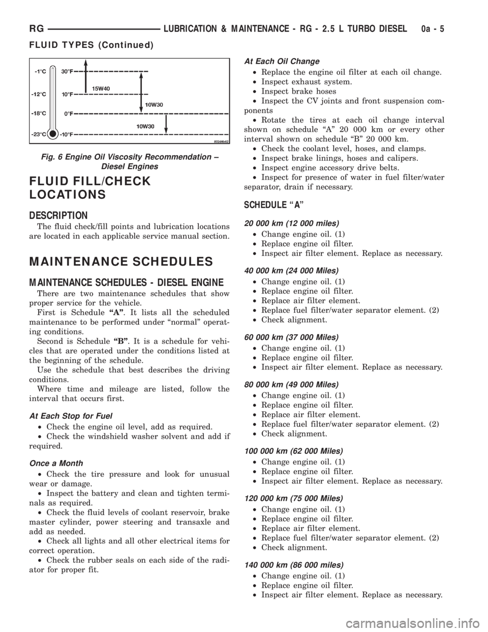
FLUID FILL/CHECK
LOCATIONS
DESCRIPTION
The fluid check/fill points and lubrication locations
are located in each applicable service manual section.
MAINTENANCE SCHEDULES
MAINTENANCE SCHEDULES - DIESEL ENGINE
There are two maintenance schedules that show
proper service for the vehicle.
First is ScheduleªAº. It lists all the scheduled
maintenance to be performed under ªnormalº operat-
ing conditions.
Second is ScheduleªBº. It is a schedule for vehi-
cles that are operated under the conditions listed at
the beginning of the schedule.
Use the schedule that best describes the driving
conditions.
Where time and mileage are listed, follow the
interval that occurs first.
At Each Stop for Fuel
²Check the engine oil level, add as required.
²Check the windshield washer solvent and add if
required.
Once a Month
²Check the tire pressure and look for unusual
wear or damage.
²Inspect the battery and clean and tighten termi-
nals as required.
²Check the fluid levels of coolant reservoir, brake
master cylinder, power steering and transaxle and
add as needed.
²Check all lights and all other electrical items for
correct operation.
²Check the rubber seals on each side of the radi-
ator for proper fit.
At Each Oil Change
²Replace the engine oil filter at each oil change.
²Inspect exhaust system.
²Inspect brake hoses
²Inspect the CV joints and front suspension com-
ponents
²Rotate the tires at each oil change interval
shown on schedule ªAº 20 000 km or every other
interval shown on schedule ªBº 20 000 km.
²Check the coolant level, hoses, and clamps.
²Inspect brake linings, hoses and calipers.
²Inspect engine accessory drive belts.
²Inspect for presence of water in fuel filter/water
separator, drain if necessary.
SCHEDULE ªAº
20 000 km (12 000 miles)
²Change engine oil. (1)
²Replace engine oil filter.
²Inspect air filter element. Replace as necessary.
40 000 km (24 000 Miles)
²Change engine oil. (1)
²Replace engine oil filter.
²Replace air filter element.
²Replace fuel filter/water separator element. (2)
²Check alignment.
60 000 km (37 000 Miles)
²Change engine oil. (1)
²Replace engine oil filter.
²Inspect air filter element. Replace as necessary.
80 000 km (49 000 Miles)
²Change engine oil. (1)
²Replace engine oil filter.
²Replace air filter element.
²Replace fuel filter/water separator element. (2)
²Check alignment.
100 000 km (62 000 Miles)
²Change engine oil. (1)
²Replace engine oil filter.
²Inspect air filter element. Replace as necessary.
120 000 km (75 000 Miles)
²Change engine oil. (1)
²Replace engine oil filter.
²Replace air filter element.
²Replace fuel filter/water separator element. (2)
²Check alignment.
140 000 km (86 000 miles)
²Change engine oil. (1)
²Replace engine oil filter.
²Inspect air filter element. Replace as necessary.
Fig. 6 Engine Oil Viscosity Recommendation ±
Diesel Engines
RGLUBRICATION & MAINTENANCE - RG - 2.5 L TURBO DIESEL0a-5
FLUID TYPES (Continued)
Page 1658 of 4284
STANDARD PROCEDURE - BRAKE FLUID
LEVEL CHECKING
Check master cylinder reservoir fluid level a mini-
mum of twice annually.
Fluid reservoirs are marked with the words FULL
and ADD to indicate proper brake fluid fill level of
the master cylinder.
If necessary, add brake fluid to bring the level to
the bottom of the FULL mark on the side of the mas-
ter cylinder fluid reservoir.
Use only Mopartbrake fluid or equivalent from a
sealed container. Brake fluid must conform to DOT 3
specifications (DOT 4 or DOT 4+ are acceptable).
DO NOTuse brake fluid with a lower boiling
point, as brake failure could result during prolonged
hard braking.
Use only brake fluid that was stored in a tightly-
sealed container.
DO NOTuse petroleum-based fluid because seal
damage will result. Petroleum based fluids would be
items such as engine oil, transmission fluid, power
steering fluid etc.
SPECIFICATIONS
BRAKE FLUID
The brake fluid used in this vehicle must conform
to DOT 3 specifications (DOT 4 and DOT 4+ are
acceptable) and SAE J1703 standards. No other type
of brake fluid is recommended or approved for usage
in the vehicle brake system. Use only MopartBrake
Fluid or equivalent from a tightly sealed container.
CAUTION: Never use reclaimed brake fluid or fluid
from an container which has been left open. An
open container of brake fluid will absorb moisture
from the air and contaminate the fluid.
CAUTION: Never use any type of a petroleum-based
fluid in the brake hydraulic system. Use of such
type fluids will result in seal damage of the vehicle
brake hydraulic system causing a failure of the
vehicle brake system. Petroleum based fluids would
be items such as engine oil, transmission fluid,
power steering fluid, etc.
JUNCTION BLOCK
DESCRIPTION - NON-ABS JUNCTION BLOCK
A junction block is used on vehicles that are not
equipped with antilock brakes (ABS). The junction
block mounts in the same location as the integrated
control unit (ICU) does on vehicles equipped withABS. This allows for use of the same brake tube con-
figuration on all vehicles. The junction block is
located on the driver's side of the front suspension
cradle/crossmember below the master cylinder (Fig.
46).
It has six threaded ports to which the brake tubes
connect. Two are for the primary and secondary
brake tubes coming from the master cylinder. The
remaining four are for the chassis brake tubes going
to each brake assembly.
OPERATION - NON-ABS JUNCTION BLOCK
The junction block distributes the brake fluid com-
ing from the master cylinder primary and secondary
ports to the four chassis brake tubes leading to the
brakes at each wheel. Since the junction block
mounts in the same location as the ABS integrated
control unit (ICU), it allows for the common use of
brake tubes going to the brakes whether the vehicle
is equipped with or without ABS.
NOTE: Although the brake tubes coming from the
master cylinder to the junction block or ABS ICU
may appear to be the same, they are not. They are
unique to each brake system application.
REMOVAL - NON-ABS JUNCTION BLOCK
(1) Using a brake pedal depressor, move and lock
the brake pedal to a position past its first 1 inch of
travel. This will prevent brake fluid from draining
out of the master cylinder when the brake tubes are
removed from the junction block.
(2) Disconnect the battery negative cable.
(3) If the vehicle is equipped with speed control,
perform the following:
(a) Disconnect the battery positive cable.
(b) Remove the battery (Refer to 8 - ELECTRI-
CAL/BATTERY SYSTEM/BATTERY - REMOVAL).
(c) Disconnect the vacuum hose connector at the
tank built into the battery tray.
(d) Remove the screw securing the coolant filler
neck to the battery tray.
(e) Remove the battery tray (Refer to 8 - ELEC-
TRICAL/BATTERY SYSTEM/TRAY - REMOVAL).
(f) Remove the fasteners and move the speed
control servo off to the side, out of the way.
CAUTION: Before removing the brake tubes from
the junction block, the junction block and the brake
tubes must be thoroughly cleaned. This is required
to prevent contamination from entering the brake
hydraulic system.
5 - 32 BRAKES - BASERS
FLUID (Continued)
Page 1664 of 4284
DIAGNOSIS AND TESTING - POWER BRAKE
BOOSTER
BASIC TEST
(1) With engine off, depress and release the brake
pedal several times to purge all vacuum from the
power brake booster.
(2) Depress and hold the pedal with light effort (15
to 25 lbs. pressure), then start the engine.
The pedal should fall slightly, then hold. Less effort
should be needed to apply the pedal at this time. If
the pedal fell as indicated, perform the VACUUM
LEAK TEST listed after the BASIC TEST. If the
pedal did not fall, continue on with this BASIC TEST.
(3) Disconnect the vacuum hose on the vacuum
check valve, then place a vacuum gauge in line
between the vacuum hose and the valve.
(4) Start the engine.
(5) When the engine is at warm operating temper-
ature, allow it to idle and check the vacuum at the
gauge.
If the vacuum supply is 12 inches Hg (40.5 kPa) or
more, the power brake booster is defective and must
be replaced. If the vacuum supply is below 12 inches
Hg, continue on with this BASIC TEST.
(6) Shut off the engine.
(7) Connect the vacuum gauge to the vacuum ref-
erence port on the engine intake manifold.
(8) Start the engine and observe the vacuum
gauge.
If the vacuum is still low, check the engine tune
and repair as necessary. If the vacuum is above 12
inches Hg, the hose or check valve to the booster has
a restriction or leak.
Once an adequate vacuum supply is obtained,
repeat the BASIC TEST.
VACUUM LEAK TEST
(1) Disconnect the vacuum hose on the vacuum
check valve, then place a vacuum gauge in line
between the vacuum hose and the valve.
(2) Start the engine.
(3) Allow the engine to warm up to normal operat-
ing temperature and engine idle.
(4) Using vacuum line pliers, close off the vacuum
supply hose near the booster, but before the vacuum
gauge, then observe the vacuum gauge.
If the vacuum drop exceeds 1.0 inch Hg (3.3 kPa)
in one minute, repeat the above steps to confirm the
reading. The vacuum loss should be less than 1.0
inch Hg in one minute time span. If the loss is more
than 1.0 inch Hg, replace the power brake booster. If
it is not, continue on with this test.
(5) Remove the pliers from the hose temporarily.
(6) Apply light effort (approximately 15 lbs. of
force) to the brake pedal and hold the pedal steady.Do not move the pedal once the pressure is applied
or the test results may vary.
(7) Have an assistant reattach the vacuum line
pliers to the vacuum supply hose.
(8) Allow 5 seconds for stabilization, then observe
the vacuum gauge.
If the vacuum drop exceeds 3.0 inches Hg (10 kPa)
in 15 seconds, repeat the above steps to confirm the
reading. The vacuum loss should be less than 3.0
inches Hg in 15 seconds time span. If the loss is
more than 3.0 inches Hg, replace the power brake
booster. If it is not, the booster is not defective.
(9) Remove the pliers and vacuum gauge.
REMOVAL - POWER BRAKE BOOSTER
CAUTION: Reserve vacuum in power brake booster
must be pumped down (removed) before removing
master cylinder from booster. This is necessary to
prevent booster from sucking in any contamination
as master cylinder is removed. This can be done
simply by pumping the brake pedal, with the vehi-
cle's engine not running, until a firm feeling brake
pedal is achieved.
(1) With engine not running, pump the brake
pedal until a firm pedal is achieved (4-5 strokes).
(2) Remove negative battery cable terminal from
battery.
(3) Remove positive battery cable terminal from
battery.
(4) Remove battery thermal guard shield.
(5) Remove battery clamp, nut and battery from
the battery tray.
(6) Remove screw securing engine coolant filler
tube to battery tray.
(7) If the vehicle is equipped with speed control,
disconnect the vacuum hose at the vacuum tank built
into the battery tray.
(8) Remove the two nuts and one bolt securing bat-
tery tray in place. Remove battery tray.
(9) If vehicle is equipped with speed control:
(a) Disconnect wiring harness connector from
the speed control servo.
(b) Remove the two servo mounting nuts.
(c) Lay speed control servo off to the side, out of
the way.
(10) Remove the wiper module (unit). (Refer to 8 -
ELECTRICAL/WIPERS/WASHERS/WIPER MOD-
ULE - REMOVAL)
(11) Disconnect wiring harness connector from
brake fluid level switch in master cylinder fluid res-
ervoir (Fig. 54).
5 - 38 BRAKES - BASERS
POWER BRAKE BOOSTER (Continued)
Page 1667 of 4284
CAUTION: The master cylinder (and its rear seal) is
used to create the seal for holding vacuum in the
vacuum booster. The vacuum seal on the master
cylinder MUST be replaced with a NEW seal when-
ever the master cylinder is removed from the vac-
uum booster.
CAUTION: When removing the vacuum seal from
the master cylinder do not use a sharp tool.
(8) Using a soft tool such as a trim stick, remove
the vacuum seal from the master cylinder mounting
flange.
(9) Install a NEW vacuum seal on rear mounting
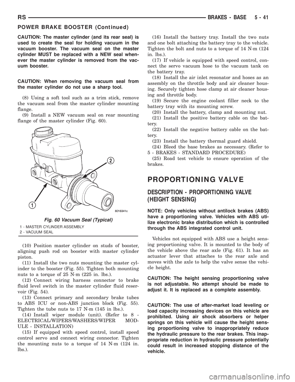
flange of the master cylinder (Fig. 60).
(10) Position master cylinder on studs of booster,
aligning push rod on booster with master cylinder
piston.
(11) Install the two nuts mounting the master cyl-
inder to the booster (Fig. 55). Tighten both mounting
nuts to a torque of 25 N´m (225 in. lbs.).
(12) Connect wiring harness connector to brake
fluid level switch in the master cylinder fluid reser-
voir (Fig. 54).
(13) Connect primary and secondary brake tubes
to ABS ICU or non-ABS junction block (Fig. 55).
Tighten the tube nuts to 17 N´m (145 in lbs.).
(14) Install wiper module (unit). (Refer to 8 -
ELECTRICAL/WIPERS/WASHERS/WIPER MOD-
ULE - INSTALLATION)
(15) If equipped with speed control, install speed
control servo and connect wiring connector. Tighten
the mounting nuts to a torque of 14 N´m (124 in.
lbs.).(16) Install the battery tray. Install the two nuts
and one bolt attaching the battery tray to the vehicle.
Tighten the bolt and nuts to a torque of 14 N´m (124
in. lbs.).
(17) If vehicle is equipped with speed control, con-
nect the servo vacuum hose to the vacuum tank on
the battery tray.
(18) Install the air inlet resonator and hoses as an
assembly on the throttle body and air cleaner hous-
ing. Securely tighten hose clamp at air cleaner hous-
ing and throttle body.
(19) Secure the engine coolant filler neck to the
battery tray with its mounting screw.
(20) Install the battery, clamp and mounting nut.
(21) Install the positive battery cable on the bat-
tery.
(22) Install the negative battery cable on the bat-
tery.
(23) Install the battery thermal guard shield.
(24) Bleed the base brakes as necessary. (Refer to
5 - BRAKES - STANDARD PROCEDURE)
(25) Road test vehicle to ensure operation of the
brakes.
PROPORTIONING VALVE
DESCRIPTION - PROPORTIONING VALVE
(HEIGHT SENSING)
NOTE: Only vehicles without antilock brakes (ABS)
have a proportioning valve. Vehicles with ABS uti-
lize electronic brake distribution which is controlled
through the ABS integrated control unit.
Vehicles not equipped with ABS use a height sens-
ing proportioning valve. It is mounted to the body of
the vehicle above the rear axle (Fig. 61). It has an
actuator lever that attaches to the rear axle and
moves with the axle to help the valve sense the vehi-
cle height.
CAUTION: The height sensing proportioning valve
is not adjustable. No attempt should be made to
adjust it. It is replaced as a complete assembly.
CAUTION: The use of after-market load leveling or
load capacity increasing devices on this vehicle are
prohibited. Using air shock absorbers or helper
springs on this vehicle will cause the height sens-
ing proportioning valve to inappropriately reduce
the hydraulic pressure to the rear brakes. This inap-
propriate reduction in hydraulic pressure potentially
could result in increased stopping distance of the
vehicle.
Fig. 60 Vacuum Seal (Typical)
1 - MASTER CYLINDER ASSEMBLY
2 - VACUUM SEAL
RSBRAKES - BASE5-41
POWER BRAKE BOOSTER (Continued)