2001 CHRYSLER VOYAGER bulb
[x] Cancel search: bulbPage 39 of 4284

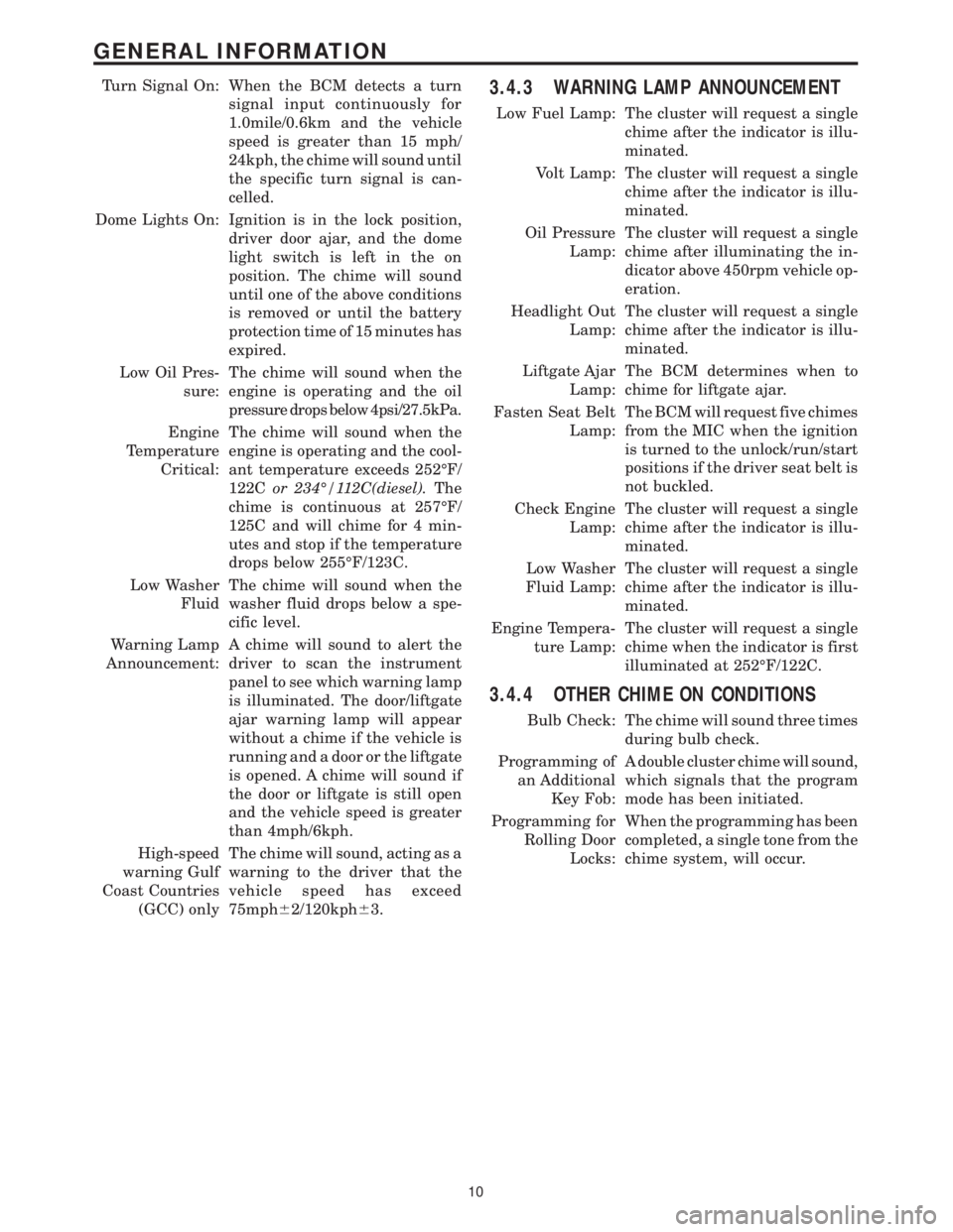
Turn Signal On: When the BCM detects a turn
signal input continuously for
1.0mile/0.6km and the vehicle
speed is greater than 15 mph/
24kph, the chime will sound until
the specific turn signal is can-
celled.
Dome Lights On: Ignition is in the lock position,
driver door ajar, and the dome
light switch is left in the on
position. The chime will sound
until one of the above conditions
is removed or until the battery
protection time of 15 minutes has
expired.
Low Oil Pres-
sure:The chime will sound when the
engine is operating and the oil
pressure drops below 4psi/27.5kPa.
Engine
Temperature
Critical:The chime will sound when the
engine is operating and the cool-
ant temperature exceeds 252ÉF/
122Cor 234É/112C(diesel).The
chime is continuous at 257ÉF/
125C and will chime for 4 min-
utes and stop if the temperature
drops below 255ÉF/123C.
Low Washer
FluidThe chime will sound when the
washer fluid drops below a spe-
cific level.
Warning Lamp
Announcement:A chime will sound to alert the
driver to scan the instrument
panel to see which warning lamp
is illuminated. The door/liftgate
ajar warning lamp will appear
without a chime if the vehicle is
running and a door or the liftgate
is opened. A chime will sound if
the door or liftgate is still open
and the vehicle speed is greater
than 4mph/6kph.
High-speed
warning Gulf
Coast Countries
(GCC) onlyThe chime will sound, acting as a
warning to the driver that the
vehicle speed has exceed
75mph62/120kph63.3.4.3 WARNING LAMP ANNOUNCEMENT
Low Fuel Lamp: The cluster will request a single
chime after the indicator is illu-
minated.
Volt Lamp: The cluster will request a single
chime after the indicator is illu-
minated.
Oil Pressure
Lamp:The cluster will request a single
chime after illuminating the in-
dicator above 450rpm vehicle op-
eration.
Headlight Out
Lamp:The cluster will request a single
chime after the indicator is illu-
minated.
Liftgate Ajar
Lamp:The BCM determines when to
chime for liftgate ajar.
Fasten Seat Belt
Lamp:The BCM will request five chimes
from the MIC when the ignition
is turned to the unlock/run/start
positions if the driver seat belt is
not buckled.
Check Engine
Lamp:The cluster will request a single
chime after the indicator is illu-
minated.
Low Washer
Fluid Lamp:The cluster will request a single
chime after the indicator is illu-
minated.
Engine Tempera-
ture Lamp:The cluster will request a single
chime when the indicator is first
illuminated at 252ÉF/122C.
3.4.4 OTHER CHIME ON CONDITIONS
Bulb Check: The chime will sound three times
during bulb check.
Programming of
an Additional
Key Fob:A double cluster chime will sound,
which signals that the program
mode has been initiated.
Programming for
Rolling Door
Locks:When the programming has been
completed, a single tone from the
chime system, will occur.
10
GENERAL INFORMATION
Page 50 of 4284

ating and the combustion air fan operation is sus-
pended for 3 seconds. Subsequently, the combustion
air fan speed is increased in two ramps within 56
seconds to nearly full load operation. After a stabi-
lization phase of 15 seconds, the combustion air fan
speed is again increased in a ramp within 50
seconds to nearly full load. After reaching full load
fuel delivery, the glow plug is deactivated and the
combustion air fan operation is increased to full
load. During the subsequent 45 seconds, as well as
in normal operation, the glow plug functions as a
flame sensor to monitor the flame condition. After
all these events, the automatically controlled heat-
ing operation starts.
In case of a no flame or a flame out condition, a
restart is automatically initiated. If the no flame
condition persists, fuel delivery is stopped and the
heater enters an error lockout mode with a run-
down of the combustion air fan. This will set one or
more DTCs in the DCHA Control's memory. If six
continuous attempts to start the heater fail due to
one or more faults in the DCHA system, the heater
enters a heater lockout mode. This will set DTC
B1813 along with any other fault(s) that the DCHA
Control identified.
3.10.3.2 HEATING
During the automatically controlled heating op-
eration, when the coolant temperature reaches
72ÉC (162ÉF), the heater will switch to a part load
operation. When the coolant temperature reaches
75ÉC (167ÉF) or if the heater runs for longer than 76
minutes the heater will switch to a control idle
period. If the coolant temperature drops to 71ÉC
(160ÉF) during a control idle period, the heater will
perform a regular starting sequence into full load
operation. A drop in coolant temperature to 65ÉC
(149ÉF) during part load operation will cause the
heater to switch to a full load operation.
3.10.3.3 DEACTIVATION
The DCHA will deactivate if the:
²engine is turned off.
²coolant temperature reaches 75ÉC (167ÉF).
²heater runs longer than 76 minutes.
²fuel tank has less than 1/8 of a tank of fuel.
²Power switch on the A/C ± Heater Control Module
is off.
²Blend Control on the A/C ± Heater Control Mod-
ule is set below 75% reheat.
When the heater is deactivated, the combustion
stops and a run-down sequence begins. During the
run-down sequence, the combustion air fan contin-
ues operation to cool down the heater. The fan is
automatically switched off after the run-down se-
quence is complete. The run-down time and thecombustion air fan speed depend on the heater
operating condition at the time of deactivation.
Run-down time is approximately 175 seconds when
deactivated in full load operation and approxi-
mately 100 seconds when deactivated in part load
operation.
3.10.4 DIAGNOSTICS
The DCHA is fully addressable with the DRBIIIt.
System tests include a Field Mode Test to activate
the DCHA for diagnostic testing purposes. The
DCHA Control will store up to three DTCs in its
memory. If the Controller detects a new fault in the
DCHA system, one that is not already stored in its
memory, it will clear the oldest of the three stored
DTCs, and it will store the new fault's DTC. If the
Controller detects a reoccurrence of a stored fault, it
will overwrite that fault's DTC with the most recent
occurrence.
3.11 INSTRUMENT CLUSTER
The Instrument Cluster receives and sends mes-
sages to other modules via the PCI bus circuit. The
indicator lamps will illuminate briefly for a bulb
check when the ignition is turned from off to run.
All of the gauges receive their information via the
PCI bus from the powertrain control module and
body control module.
The gauges and the LEDs are not individually
replaceable thereby requiring complete replace-
ment of the Instrument Cluster if a repair is neces-
sary. In the event that the Instrument Cluster loses
communication with other modules on the PCI bus,
the cluster will display ªno busº in the VF display.
The Trip/Reset button is used to switch the dis-
play from trip to total mileage. Holding the button
when the display is in the trip mode will reset the
trip mileage. This button is also used to put the
cluster in self-diagnostic mode. The odometer dis-
play uses blue-green vacuum fluorescent digital
characters.
On base vehicles, the Instrument Cluster has
three gauges: Speedometer, Fuel and Engine Cool-
ant Temperature. A red dot moves transversely
through openings in the Instrument Cluster face
(P-R-N-D-2-1) to indicate the gear selected.
With all other models, the Instrument Cluster
also includes a Tachometer and uses a vacuum-
fluorescent shift indicator.
The odometer display and door/liftgate ajar indi-
cators turn on when a door is opened to assist both
the customer and service technician to view the
odometer without turning the ignition on.
21
GENERAL INFORMATION
Page 105 of 4284

When Monitored and Set Condition:
ORC, CALIBRATION MISMATCH - STORED
When Monitored: With ignition on, the ORC monitors the PCI Bus for the VIN message
containing the body style. The PCM transmits the 17- character VIN message every 14
seconds. Note: The VIN message should match the vehicle VIN plate.
Set Condition: If the Body style stored in ORC does not exactly match the vehicle body
style indicated by the PCM, then the fault shall be set.
ORC, CLUSTER MESSAGE MISMATCH - STORED
When Monitored: After the MIC bulb test is completed, the ORC compares the Lamp
Request by ORC (On or Off) and the Lamp on by MIC (On or Off) PCI Bus messages. Each
message is transmitted one time per second or when a change in the lamp state occur.
Set Condition: If the Lamp Request by ORC (On or Off) and the Lamp on by MIC (On or
Off) messages do not match, the code will set.
ORC, DRIVER SBS OPEN - STORED
When Monitored: The ORC monitors the Seat Belt Switch circuit for an open condition.
Set Condition: The code will set if the ORC does not detect the correct circuit voltage.
ORC, DRIVER SBS SHORT TO BATTERY - STORED
When Monitored: The ORC monitors the Seat Belt Switch circuit for an short to battery.
Set Condition: The code will set if the ORC detects high circuit voltage.
ORC, DRIVER SBS SHORT TO GROUND - STORED
When Monitored: The ORC monitors the Seat Belt Switch circuit for a shorted together
or shorted to ground condition.
Set Condition: The code will set if the ORC detects low circuit voltage.
ORC, DRIVER SBT CIRCUIT OPEN - STORED
When Monitored: When the ignition is On, the ORC monitors the resistance of the Driver
Seat Belt Tensioner circuits.
Set Condition: The ORC has detected an open circuit or high resistance on the Driver
Seat Belt Tensioner circuits.
ORC, DRIVER SBT CIRCUIT SHORT - STORED
When Monitored: When the ignition is on, the ORC monitors the resistance of the Driver
Seat Belt Tensioner circuits.
Set Condition: The ORC has detected low resistance in the Driver Seat Belt Tensioner
circuits.
76
AIRBAG
ORC, CALIBRATION MISMATCH - STORED ÐContinued
Page 111 of 4284

Symptom:
ORC, CLUSTER MESSAGE MISMATCH - ACTIVE
When Monitored and Set Condition:
ORC, CLUSTER MESSAGE MISMATCH - ACTIVE
When Monitored: After the MIC bulb test is completed, the ORC compares the Lamp
Request by ORC, On or Off, and the Lamp on by MIC, On or Off, PCI Bus messages. Each
message is transmitted one time per second or when a change in the lamp state occur.
Set Condition: If the Lamp Request by ORC, On or Off, and the Lamp on by MIC, On or
Off, messages do not match, the code will set.
POSSIBLE CAUSES
MIC, COMMUNICATION FAILURE
MIC, CLUSTER MESSAGE MISMATCH
ORC, CLUSTER MESSAGE MISMATCH
TEST ACTION APPLICABILITY
1 Turn the ignition on.
With the DRBIIIt, ensure PCI Bus communications with the Instrument Cluster.
Is the Instrument Cluster communicating on the PCI Bus?All
Ye s®Go To 2
No®Refer to category COMMUNICATION CATEGORY and select the
related symptom INSTRUMENT CLUSTER BUS +/- SIGNAL
OPEN.
Perform AIRBAG VERIFICATION TEST - VER 1.
2 With the DRB select PASSIVE RESTRAINTS, AIRBAG, MONITOR DISPLAY and
WARNING LAMP STATUS.
Cycle the ignition key and observe the LAMP ON BY MIC and LAMP REQ BY ORC
monitors after the 6 to 8 second indicator test.
Does the LAMP ON BY MIC and LAMP REQ BY ORC monitors match?All
YES
Go To 3
NO
Replace Mechanical Instrument Cluster.
Perform BODY VERIFICATION TEST - VER 1.
82
AIRBAG
Page 155 of 4284

Symptom:
ORC, NO CLUSTER MESSAGE - ACTIVE
When Monitored and Set Condition:
ORC, NO CLUSTER MESSAGE - ACTIVE
When Monitored: With the ignition in the On position, the ORC monitors the PCI Bus for
a message from the MIC containing the airbag warning lamp status. The MIC transmits
the message one time at ignition on, lamp state change, or in response to the ORC lamp
message.
Set Condition: If the MIC message is not received for 10 consecutive seconds, the code
will set.
POSSIBLE CAUSES
MIC, COMMUNICATION FAILURE
NO CLUSTER MESSAGES
ORC, NO CLUSTER MESSAGES
TEST ACTION APPLICABILITY
1 Turn the ignition on.
With the DRBIIIt, ensure PCI Bus communications with the Instrument Cluster.
Is the Instrument Cluster communicating on the PCI Bus?All
Ye s®Go To 2
No®Refer to category COMMUNICATION CATEGORY and select the
related symptom INSTRUMENT CLUSTER BUS +/- SIGNAL
OPEN.
Perform AIRBAG VERIFICATION TEST - VER 1.
2 With the DRB select PASSIVE RESTRAINTS, AIRBAG, MONITOR DISPLAY and
WARNING LAMP STATUS.
Cycle the ignition key and observe the LAMP ON BY MIC monitor after the 6 to 8
seconds bulb check.
Does the DRB show LAMP ON BY MIC: ON or OFF?All
YES
Go To 3
NO
Replace Instrument Cluster circuit board.
Perform BODY VERIFICATION TEST - VER 1.
126
AIRBAG
Page 492 of 4284

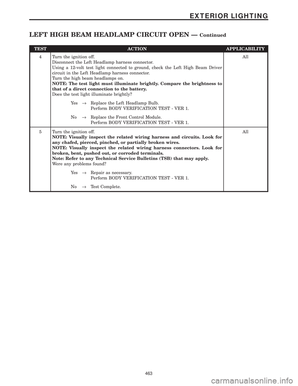
TEST ACTION APPLICABILITY
4 Turn the ignition off.
Disconnect the Left Headlamp harness connector.
Using a 12-volt test light connected to ground, check the Left High Beam Driver
circuit in the Left Headlamp harness connector.
Turn the high beam headlamps on.
NOTE: The test light must illuminate brightly. Compare the brightness to
that of a direct connection to the battery.
Does the test light illuminate brightly?All
Ye s®Replace the Left Headlamp Bulb.
Perform BODY VERIFICATION TEST - VER 1.
No®Replace the Front Control Module.
Perform BODY VERIFICATION TEST - VER 1.
5 Turn the ignition off.
NOTE: Visually inspect the related wiring harness and circuits. Look for
any chafed, pierced, pinched, or partially broken wires.
NOTE: Visually inspect the related wiring harness connectors. Look for
broken, bent, pushed out, or corroded terminals.
Note: Refer to any Technical Service Bulletins (TSB) that may apply.
Were any problems found?All
Ye s®Repair as necessary.
Perform BODY VERIFICATION TEST - VER 1.
No®Test Complete.
463
EXTERIOR LIGHTING
LEFT HIGH BEAM HEADLAMP CIRCUIT OPEN ÐContinued
Page 493 of 4284

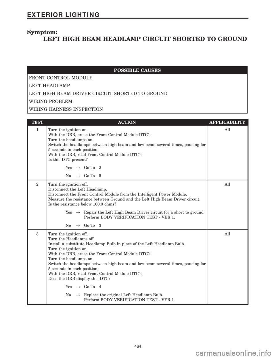
Symptom:
LEFT HIGH BEAM HEADLAMP CIRCUIT SHORTED TO GROUND
POSSIBLE CAUSES
FRONT CONTROL MODULE
LEFT HEADLAMP
LEFT HIGH BEAM DRIVER CIRCUIT SHORTED TO GROUND
WIRING PROBLEM
WIRING HARNESS INSPECTION
TEST ACTION APPLICABILITY
1 Turn the ignition on.
With the DRB, erase the Front Control Module DTC's.
Turn the headlamps on.
Switch the headlamps between high beam and low beam several times, pausing for
5 seconds in each position.
With the DRB, read Front Control Module DTC's.
Is this DTC present?All
Ye s®Go To 2
No®Go To 5
2 Turn the ignition off.
Disconnect the Left Headlamp.
Disconnect the Front Control Module from the Intelligent Power Module.
Measure the resistance between Ground and the Left High Beam Driver circuit.
Is the resistance below 100.0 ohms?All
Ye s®Repair the Left High Beam Driver circuit for a short to ground
Perform BODY VERIFICATION TEST - VER 1.
No®Go To 3
3 Turn the ignition off.
Turn the Headlamps off.
Install a substitute Headlamp Bulb in place of the Left Headlamp Bulb.
Turn the ignition on.
With the DRB, erase the Front Control Module DTC's.
Turn the headlamps on.
Switch the headlamps between high beam and low beam several times, pausing for
5 seconds in each position.
With the DRB, read Front Control Module DTC's.
Does the DRB display this DTC?All
Ye s®Go To 4
No®Replace the original Left Headlamp Bulb.
Perform BODY VERIFICATION TEST - VER 1.
464
EXTERIOR LIGHTING
Page 496 of 4284

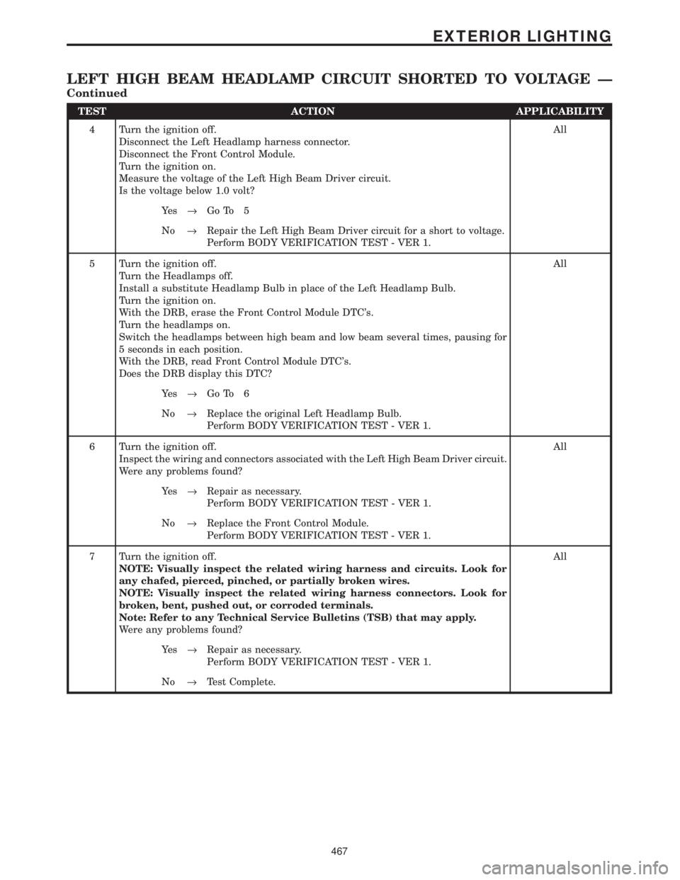
TEST ACTION APPLICABILITY
4 Turn the ignition off.
Disconnect the Left Headlamp harness connector.
Disconnect the Front Control Module.
Turn the ignition on.
Measure the voltage of the Left High Beam Driver circuit.
Is the voltage below 1.0 volt?All
Ye s®Go To 5
No®Repair the Left High Beam Driver circuit for a short to voltage.
Perform BODY VERIFICATION TEST - VER 1.
5 Turn the ignition off.
Turn the Headlamps off.
Install a substitute Headlamp Bulb in place of the Left Headlamp Bulb.
Turn the ignition on.
With the DRB, erase the Front Control Module DTC's.
Turn the headlamps on.
Switch the headlamps between high beam and low beam several times, pausing for
5 seconds in each position.
With the DRB, read Front Control Module DTC's.
Does the DRB display this DTC?All
Ye s®Go To 6
No®Replace the original Left Headlamp Bulb.
Perform BODY VERIFICATION TEST - VER 1.
6 Turn the ignition off.
Inspect the wiring and connectors associated with the Left High Beam Driver circuit.
Were any problems found?All
Ye s®Repair as necessary.
Perform BODY VERIFICATION TEST - VER 1.
No®Replace the Front Control Module.
Perform BODY VERIFICATION TEST - VER 1.
7 Turn the ignition off.
NOTE: Visually inspect the related wiring harness and circuits. Look for
any chafed, pierced, pinched, or partially broken wires.
NOTE: Visually inspect the related wiring harness connectors. Look for
broken, bent, pushed out, or corroded terminals.
Note: Refer to any Technical Service Bulletins (TSB) that may apply.
Were any problems found?All
Ye s®Repair as necessary.
Perform BODY VERIFICATION TEST - VER 1.
No®Test Complete.
467
EXTERIOR LIGHTING
LEFT HIGH BEAM HEADLAMP CIRCUIT SHORTED TO VOLTAGE Ð
Continued