2001 CHRYSLER VOYAGER wipers
[x] Cancel search: wipersPage 28 of 4284
TABLE OF CONTENTS - Continued
10.17POWER FOLDING MIRROR LHD...................................1112
10.18POWER FOLDING MIRROR RHD...................................1113
10.19POWER DOOR LOCKS/RKE.......................................1114
10.20POWER LIFTGATE SYSTEM.......................................1115
10.21POWER SLIDING DOOR SYSTEM..................................1116
10.22REAR DEFOG/HEATED MIRROR/FRONT WIPER DE-ICE...............1117
10.23SLIDING DOOR AND LIFTGATE SWITCHES..........................1118
10.24VEHICLE THEFT SECURITY SYSTEM...............................1119
10.24.1BASE ALARM SYSTEM..................................1119
10.24.2THATCHAM ALARM SYSTEM.............................1120
10.25WIPERS - FRONT AND REAR......................................1121
11.0 CHARTS AND GRAPHS...............................................1122
11.1KDB LAB SCOPE PATTERN.......................................1123
11.2PCI BUS LAB SCOPE PATTERN....................................1124
xxv
Page 44 of 4284
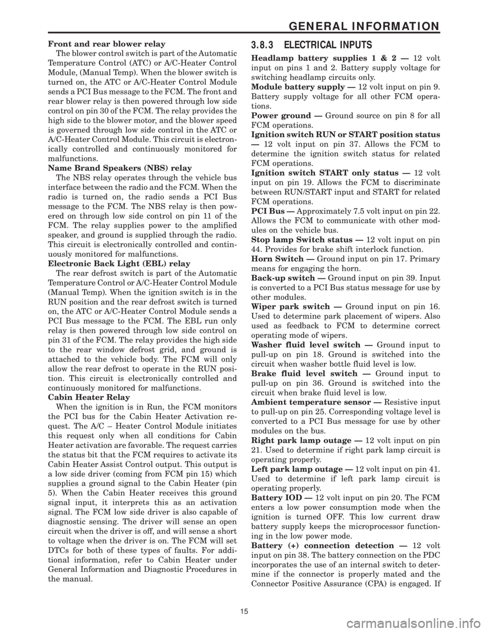
Front and rear blower relay
The blower control switch is part of the Automatic
Temperature Control (ATC) or A/C-Heater Control
Module, (Manual Temp). When the blower switch is
turned on, the ATC or A/C-Heater Control Module
sends a PCI Bus message to the FCM. The front and
rear blower relay is then powered through low side
control on pin 30 of the FCM. The relay provides the
high side to the blower motor, and the blower speed
is governed through low side control in the ATC or
A/C-Heater Control Module. This circuit is electron-
ically controlled and continuously monitored for
malfunctions.
Name Brand Speakers (NBS) relay
The NBS relay operates through the vehicle bus
interface between the radio and the FCM. When the
radio is turned on, the radio sends a PCI Bus
message to the FCM. The NBS relay is then pow-
ered on through low side control on pin 11 of the
FCM. The relay supplies power to the amplified
speaker, and ground is supplied through the radio.
This circuit is electronically controlled and contin-
uously monitored for malfunctions.
Electronic Back Light (EBL) relay
The rear defrost switch is part of the Automatic
Temperature Control or A/C-Heater Control Module
(Manual Temp). When the ignition switch is in the
RUN position and the rear defrost switch is turned
on, the ATC or A/C-Heater Control Module sends a
PCI Bus message to the FCM. The EBL run only
relay is then powered through low side control on
pin 31 of the FCM. The relay provides the high side
to the rear window defrost grid, and ground is
attached to the vehicle body. The FCM will only
allow the rear defrost to operate in the RUN posi-
tion. This circuit is electronically controlled and
continuously monitored for malfunctions.
Cabin Heater Relay
When the ignition is in Run, the FCM monitors
the PCI bus for the Cabin Heater Activation re-
quest. The A/C ± Heater Control Module initiates
this request only when all conditions for Cabin
Heater activation are favorable. The request carries
the status bit that the FCM requires to activate its
Cabin Heater Assist Control output. This output is
a low side driver (coming from FCM pin 15) which
supplies a ground signal to the Cabin Heater (pin
5). When the Cabin Heater receives this ground
signal input, it interprets this as an activation
signal. The FCM low side driver is also capable of
diagnostic sensing. The driver will sense an open
circuit when the driver is off, and will sense a short
to voltage when the driver is on. The FCM will set
DTCs for both of these types of faults. For addi-
tional information, refer to Cabin Heater under
General Information and Diagnostic Procedures in
the manual.3.8.3 ELECTRICAL INPUTS
Headlamp battery supplies1&2Ð12 volt
input on pins 1 and 2. Battery supply voltage for
switching headlamp circuits only.
Module battery supply Ð12 volt input on pin 9.
Battery supply voltage for all other FCM opera-
tions.
Power ground ÐGround source on pin 8 for all
FCM operations.
Ignition switch RUN or START position status
Ð12 volt input on pin 37. Allows the FCM to
determine the ignition switch status for related
FCM operations.
Ignition switch START only status Ð12 volt
input on pin 19. Allows the FCM to discriminate
between RUN/START input and START for related
FCM operations.
PCI Bus ÐApproximately 7.5 volt input on pin 22.
Allows the FCM to communicate with other mod-
ules on the vehicle bus.
Stop lamp Switch status Ð12 volt input on pin
44. Provides for brake shift interlock function.
Horn Switch ÐGround input on pin 17. Primary
means for engaging the horn.
Back-up switch ÐGround input on pin 39. Input
is converted to a PCI Bus status message for use by
other modules.
Wiper park switch ÐGround input on pin 16.
Used to determine park placement of wipers. Also
used as feedback to FCM to determine correct
operating mode of wipers.
Washer fluid level switch ÐGround input to
pull-up on pin 18. Ground is switched into the
circuit when washer bottle fluid level is low.
Brake fluid level switch ÐGround input to
pull-up on pin 36. Ground is switched into the
circuit when brake fluid level is low.
Ambient temperature sensor ÐResistive input
to pull-up on pin 25. Corresponding voltage level is
converted to a PCI Bus message for use by other
modules on the bus.
Right park lamp outage Ð12 volt input on pin
21. Used to determine if right park lamp circuit is
operating properly.
Left park lamp outage Ð12 volt input on pin 41.
Used to determine if left park lamp circuit is
operating properly.
Battery IOD Ð12 volt input on pin 20. The FCM
enters a low power consumption mode when the
ignition is turned OFF. This low current draw
battery supply keeps the microprocessor function-
ing in the low power mode.
Battery (+) connection detection Ð12 volt
input on pin 38. The battery connection on the PDC
incorporates the use of an internal switch to deter-
mine if the connector is properly mated and the
Connector Positive Assurance (CPA) is engaged. If
15
GENERAL INFORMATION
Page 56 of 4284

NOTE: A POWERTRAIN CONTROL MODULE
FROM A VEHICLE EQUIPPED WITH A
VEHICLE THEFT SECURITY SYSTEM
CANNOT BE USED IN A VEHICLE THAT IS
NOT EQUIPPED WITH A VEHICLE THEFT
SECURITY SYSTEM IF THE VTSS INDICATOR
LAMP COMES ON AFTER IGNITION ON AND
STAYS ON, THE PCI BUS COMMUNICATION
WITH THE POWERTRAIN CONTROL
MODULE HAS POSSIBLY BEEN LOST.
3.20.2 THATCHAM ALARM SYSTEM
The Thatcham Alarm Module monitors the vehi-
cle doors, liftgate, hood and the interior of the
vehicle for unauthorized operation. The vehicle
doors, liftgate, and hood use ajar switches as inputs
to the BCM to indicate their current status. The
interior of the vehicle is secured by the use of
Intrusion Sensors. The Intrusion Sensors are used
as inputs to the RKE/Thatcham Alarm Module to
report any motion in the interior of the vehicle. The
alarm activates by sounding the siren, flashing the
hazard lamps, and the VTSS Indicator Lamp.
Arming
Before arming, all doors, liftgate, and the hood
must be completely closed. The system can then be
armed by following a normal exit sequence, of
opening the door and then locking the doors with
the door lock switch and then closing the door. The
system can also be armed by opening the door,
closing the door and then locking the doors with the
RKE transmitter.
Disarming
To disarm the alarm system, the RKE transmit-
ter is used. The RKE transmitter will unlock the
vehicle doors and disarm the alarm system. The
RKE transmitter can also be used to halt the alarm
once it has been activated.
3.21 WIPER SYSTEM
3.21.1 FRONT WIPER
The front wiper/washer system consists of the
following features: lo-hi-speed, mist wipers, inter-
mittent wipers and wipe after wash. The front
wiper system is only active when the ignition switch
is in the RUN/ACC position. The vehicle operator
selects the front wiper function using the front
wiper switch (a resistive multiplexed stalk switch)
which is integral to the Multi-Function Switch. The
front wiper switch is hardwired to the Body Control
Module (BCM). Upon receiving a wiper switch sig-
nal, the BCM sends a PCI Bus message to the Front
Control Module (FCM). The FCM controls the ON/OFF relay, the HIGH/LOW relay and the front and
rear washer pump motors.
The Wiper system utilizes the BCM to control the
on/off and hi/low relays for the low and hi speed
wiper functions, intermittent wiper delay as the
switch position changes, pulse wipe, wipe after
wash mode and wiper motor functions. The BCM
uses the vehicle speed input to double the usual
delay time below 10 MPH (6 KPH).
3.21.2 SPEED SENSITIVE INTERMITTENT
WIPE MODE
There are 5 individual delay time settings with a
minimum delay of 1.7 seconds to a maximum of 18.4
seconds. When the vehicle speed is under 10 MPH
(6 KPM), the delay time is doubled, providing a
delay range of 3.4 seconds to 36.8 seconds.
3.21.3 PULSE WIPE
When the wiper is in the off position and the
driver presses the wash button for more than .062
seconds, but less than .5 seconds, 2 wipe cycles in
low speed mode will be provided.
3.21.4 PARK AFTER IGNITION OFF
Because the wiper relays are powered from the
battery, the BCM can run the wipers to park after
the ignition is turned off.
3.21.5 WIPE AFTER WASH
When the driver presses the wash button for over
.5 seconds and releases it, the wiper will continue to
run for 2 additional wipe cycles.
3.21.6 REAR WIPER
The rear wiper/washer system consists of the
following features: mist wipers, intermittent wipers
and wipe after wash. The rear wiper system is only
active when the ignition switch is in the RUN/ACC
position. The vehicle operator selects the rear wiper
function using one of the three buttons on the dash
mounted rear wiper switch. The rear wiper switch
is hardwired to the Body Control Module (BCM).
Upon receiving a wiper switch signal, the BCM
provides 12 volts to the rear wiper motor. Rear
washer occurs when the BCM receives a rear
washer switch ON input. The BCM sends a PCI Bus
message to the FCM requesting rear washer on.
The FCM activates the rear washer by providing a
ground for the rear washer motor.
3.21.7 SPEED SENSITIVE INTERMITTENT
WIPE MODE
The delay setting of the rear wiper system is
based solely on the vehicle speed. The delay time is
27
GENERAL INFORMATION
Page 985 of 4284
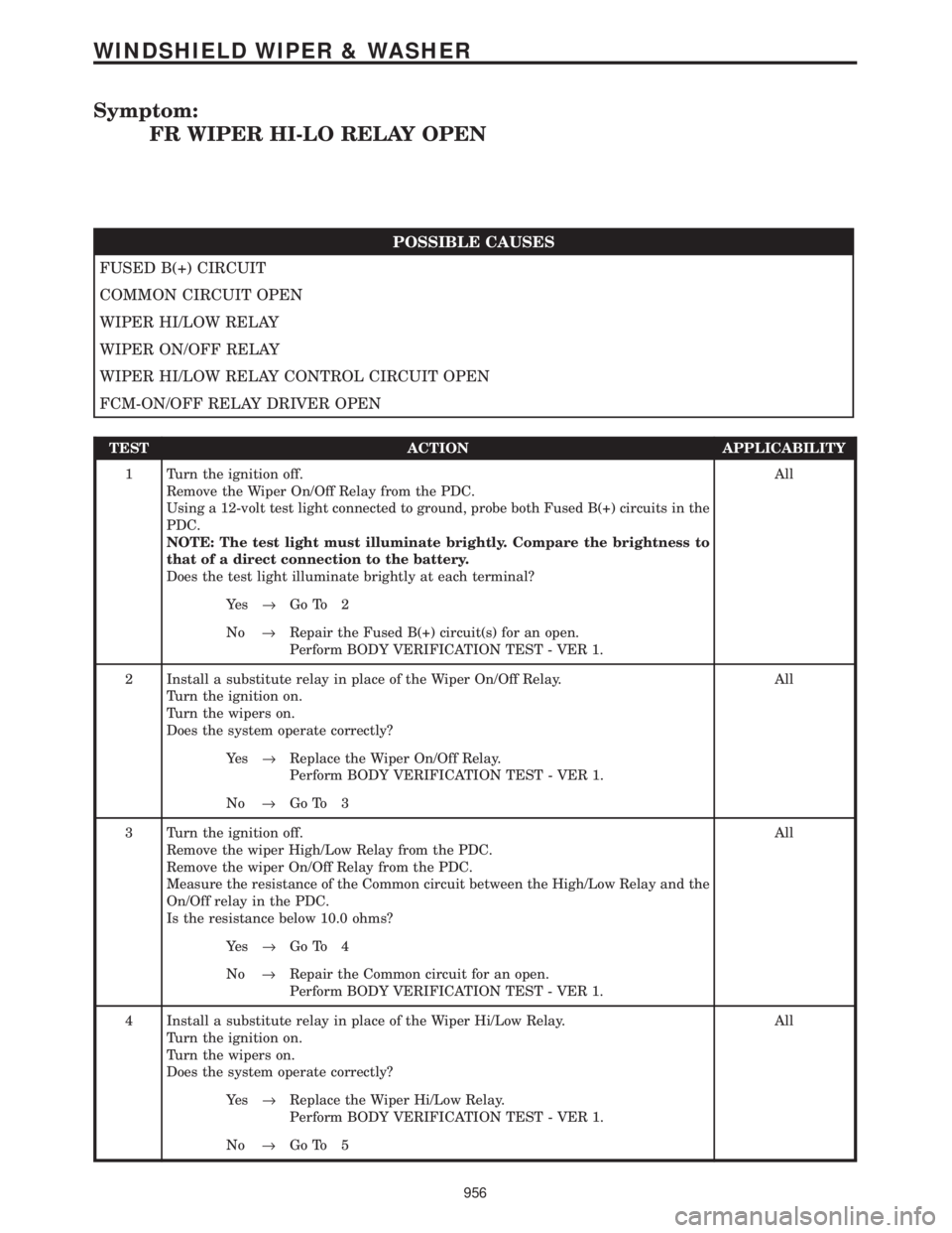
Symptom:
FR WIPER HI-LO RELAY OPEN
POSSIBLE CAUSES
FUSED B(+) CIRCUIT
COMMON CIRCUIT OPEN
WIPER HI/LOW RELAY
WIPER ON/OFF RELAY
WIPER HI/LOW RELAY CONTROL CIRCUIT OPEN
FCM-ON/OFF RELAY DRIVER OPEN
TEST ACTION APPLICABILITY
1 Turn the ignition off.
Remove the Wiper On/Off Relay from the PDC.
Using a 12-volt test light connected to ground, probe both Fused B(+) circuits in the
PDC.
NOTE: The test light must illuminate brightly. Compare the brightness to
that of a direct connection to the battery.
Does the test light illuminate brightly at each terminal?All
Ye s®Go To 2
No®Repair the Fused B(+) circuit(s) for an open.
Perform BODY VERIFICATION TEST - VER 1.
2 Install a substitute relay in place of the Wiper On/Off Relay.
Turn the ignition on.
Turn the wipers on.
Does the system operate correctly?All
Ye s®Replace the Wiper On/Off Relay.
Perform BODY VERIFICATION TEST - VER 1.
No®Go To 3
3 Turn the ignition off.
Remove the wiper High/Low Relay from the PDC.
Remove the wiper On/Off Relay from the PDC.
Measure the resistance of the Common circuit between the High/Low Relay and the
On/Off relay in the PDC.
Is the resistance below 10.0 ohms?All
Ye s®Go To 4
No®Repair the Common circuit for an open.
Perform BODY VERIFICATION TEST - VER 1.
4 Install a substitute relay in place of the Wiper Hi/Low Relay.
Turn the ignition on.
Turn the wipers on.
Does the system operate correctly?All
Ye s®Replace the Wiper Hi/Low Relay.
Perform BODY VERIFICATION TEST - VER 1.
No®Go To 5
956
WINDSHIELD WIPER & WASHER
Page 987 of 4284
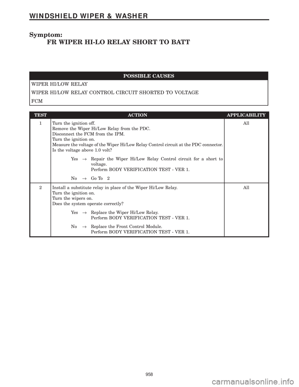
Symptom:
FR WIPER HI-LO RELAY SHORT TO BATT
POSSIBLE CAUSES
WIPER HI/LOW RELAY
WIPER HI/LOW RELAY CONTROL CIRCUIT SHORTED TO VOLTAGE
FCM
TEST ACTION APPLICABILITY
1 Turn the ignition off.
Remove the Wiper Hi/Low Relay from the PDC.
Disconnect the FCM from the IPM.
Turn the ignition on.
Measure the voltage of the Wiper Hi/Low Relay Control circuit at the PDC connector.
Is the voltage above 1.0 volt?All
Ye s®Repair the Wiper Hi/Low Relay Control circuit for a short to
voltage.
Perform BODY VERIFICATION TEST - VER 1.
No®Go To 2
2 Install a substitute relay in place of the Wiper Hi/Low Relay.
Turn the ignition on.
Turn the wipers on.
Does the system operate correctly?All
Ye s®Replace the Wiper Hi/Low Relay.
Perform BODY VERIFICATION TEST - VER 1.
No®Replace the Front Control Module.
Perform BODY VERIFICATION TEST - VER 1.
958
WINDSHIELD WIPER & WASHER
Page 992 of 4284
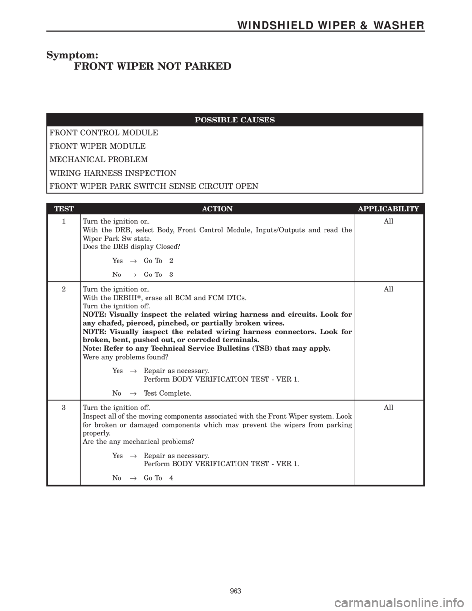
Symptom:
FRONT WIPER NOT PARKED
POSSIBLE CAUSES
FRONT CONTROL MODULE
FRONT WIPER MODULE
MECHANICAL PROBLEM
WIRING HARNESS INSPECTION
FRONT WIPER PARK SWITCH SENSE CIRCUIT OPEN
TEST ACTION APPLICABILITY
1 Turn the ignition on.
With the DRB, select Body, Front Control Module, Inputs/Outputs and read the
Wiper Park Sw state.
Does the DRB display Closed?All
Ye s®Go To 2
No®Go To 3
2 Turn the ignition on.
With the DRBIIIt, erase all BCM and FCM DTCs.
Turn the ignition off.
NOTE: Visually inspect the related wiring harness and circuits. Look for
any chafed, pierced, pinched, or partially broken wires.
NOTE: Visually inspect the related wiring harness connectors. Look for
broken, bent, pushed out, or corroded terminals.
Note: Refer to any Technical Service Bulletins (TSB) that may apply.
Were any problems found?All
Ye s®Repair as necessary.
Perform BODY VERIFICATION TEST - VER 1.
No®Test Complete.
3 Turn the ignition off.
Inspect all of the moving components associated with the Front Wiper system. Look
for broken or damaged components which may prevent the wipers from parking
properly.
Are the any mechanical problems?All
Ye s®Repair as necessary.
Perform BODY VERIFICATION TEST - VER 1.
No®Go To 4
963
WINDSHIELD WIPER & WASHER
Page 994 of 4284
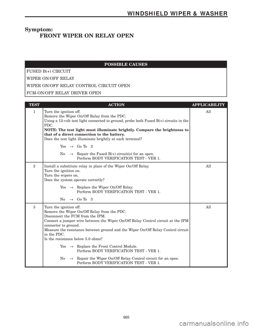
Symptom:
FRONT WIPER ON RELAY OPEN
POSSIBLE CAUSES
FUSED B(+) CIRCUIT
WIPER ON/OFF RELAY
WIPER ON/OFF RELAY CONTROL CIRCUIT OPEN
FCM-ON/OFF RELAY DRIVER OPEN
TEST ACTION APPLICABILITY
1 Turn the ignition off.
Remove the Wiper On/Off Relay from the PDC.
Using a 12-volt test light connected to ground, probe both Fused B(+) circuits in the
PDC.
NOTE: The test light must illuminate brightly. Compare the brightness to
that of a direct connection to the battery.
Does the test light illuminate brightly at each terminal?All
Ye s®Go To 2
No®Repair the Fused B(+) circuit(s) for an open.
Perform BODY VERIFICATION TEST - VER 1.
2 Install a substitute relay in place of the Wiper On/Off Relay.
Turn the ignition on.
Turn the wipers on.
Does the system operate correctly?All
Ye s®Replace the Wiper On/Off Relay.
Perform BODY VERIFICATION TEST - VER 1.
No®Go To 3
3 Turn the ignition off.
Remove the Wiper On/Off Relay from the PDC.
Disconnect the FCM from the IPM.
Connect a jumper wire between the Wiper On/Off Relay Control circuit at the IPM
connector to ground.
Measure the resistance between ground and the Wiper On/Off Relay Control circuit
in the PDC.
Is the resistance below 5.0 ohms?All
Ye s®Replace the Front Control Module.
Perform BODY VERIFICATION TEST - VER 1.
No®Repair the Wiper On/Off Relay Control circuit for an open.
Perform BODY VERIFICATION TEST - VER 1.
965
WINDSHIELD WIPER & WASHER
Page 995 of 4284
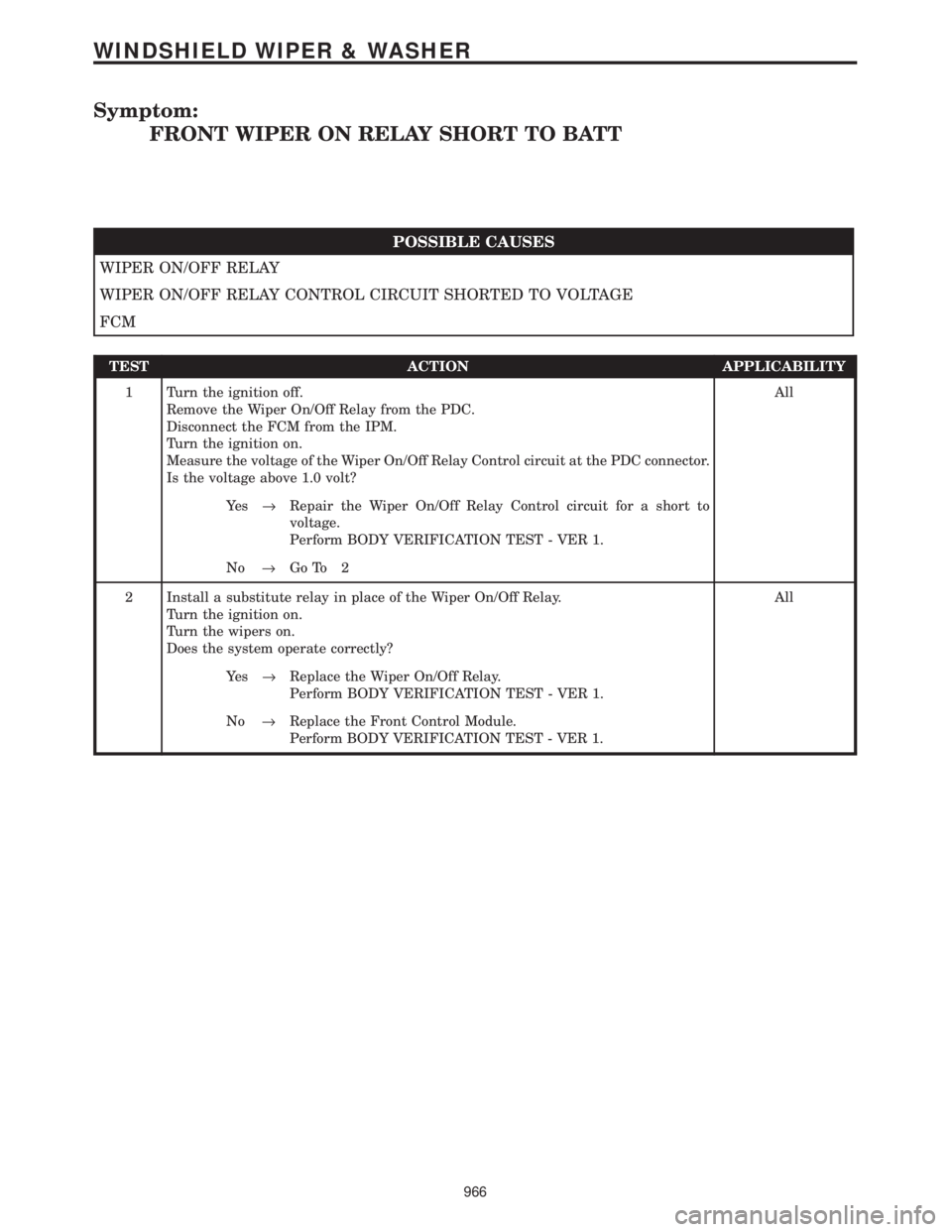
Symptom:
FRONT WIPER ON RELAY SHORT TO BATT
POSSIBLE CAUSES
WIPER ON/OFF RELAY
WIPER ON/OFF RELAY CONTROL CIRCUIT SHORTED TO VOLTAGE
FCM
TEST ACTION APPLICABILITY
1 Turn the ignition off.
Remove the Wiper On/Off Relay from the PDC.
Disconnect the FCM from the IPM.
Turn the ignition on.
Measure the voltage of the Wiper On/Off Relay Control circuit at the PDC connector.
Is the voltage above 1.0 volt?All
Ye s®Repair the Wiper On/Off Relay Control circuit for a short to
voltage.
Perform BODY VERIFICATION TEST - VER 1.
No®Go To 2
2 Install a substitute relay in place of the Wiper On/Off Relay.
Turn the ignition on.
Turn the wipers on.
Does the system operate correctly?All
Ye s®Replace the Wiper On/Off Relay.
Perform BODY VERIFICATION TEST - VER 1.
No®Replace the Front Control Module.
Perform BODY VERIFICATION TEST - VER 1.
966
WINDSHIELD WIPER & WASHER