2001 CHRYSLER VOYAGER wipers
[x] Cancel search: wipersPage 1793 of 4284
ENGINE COOLANT TEMP
SENSOR
DESCRIPTION
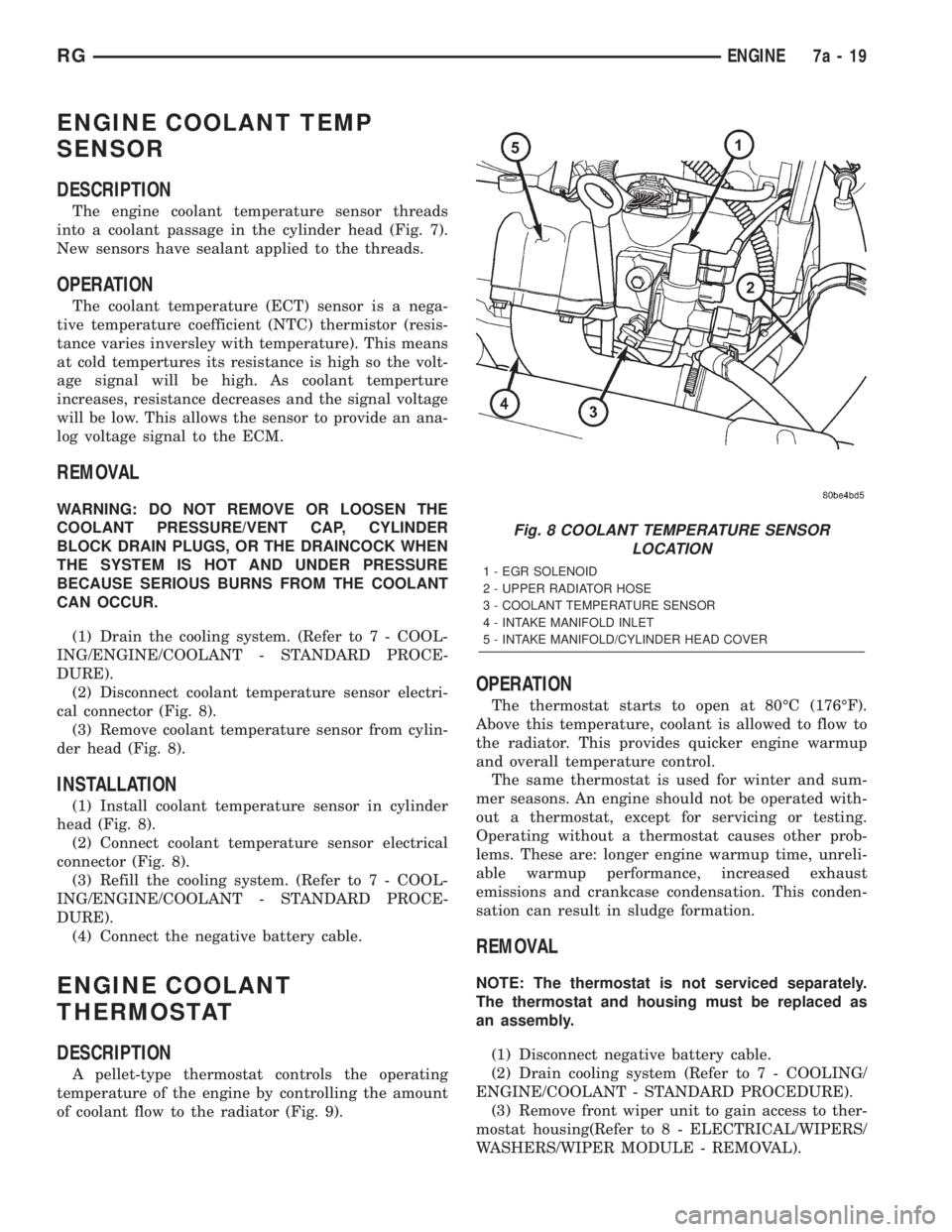
The engine coolant temperature sensor threads
into a coolant passage in the cylinder head (Fig. 7).
New sensors have sealant applied to the threads.
OPERATION
The coolant temperature (ECT) sensor is a nega-
tive temperature coefficient (NTC) thermistor (resis-
tance varies inversley with temperature). This means
at cold tempertures its resistance is high so the volt-
age signal will be high. As coolant temperture
increases, resistance decreases and the signal voltage
will be low. This allows the sensor to provide an ana-
log voltage signal to the ECM.
REMOVAL
WARNING: DO NOT REMOVE OR LOOSEN THE
COOLANT PRESSURE/VENT CAP, CYLINDER
BLOCK DRAIN PLUGS, OR THE DRAINCOCK WHEN
THE SYSTEM IS HOT AND UNDER PRESSURE
BECAUSE SERIOUS BURNS FROM THE COOLANT
CAN OCCUR.
(1) Drain the cooling system. (Refer to 7 - COOL-
ING/ENGINE/COOLANT - STANDARD PROCE-
DURE).
(2) Disconnect coolant temperature sensor electri-
cal connector (Fig. 8).
(3) Remove coolant temperature sensor from cylin-
der head (Fig. 8).
INSTALLATION
(1) Install coolant temperature sensor in cylinder
head (Fig. 8).
(2) Connect coolant temperature sensor electrical
connector (Fig. 8).
(3) Refill the cooling system. (Refer to 7 - COOL-
ING/ENGINE/COOLANT - STANDARD PROCE-
DURE).
(4) Connect the negative battery cable.
ENGINE COOLANT
THERMOSTAT
DESCRIPTION
A pellet-type thermostat controls the operating
temperature of the engine by controlling the amount
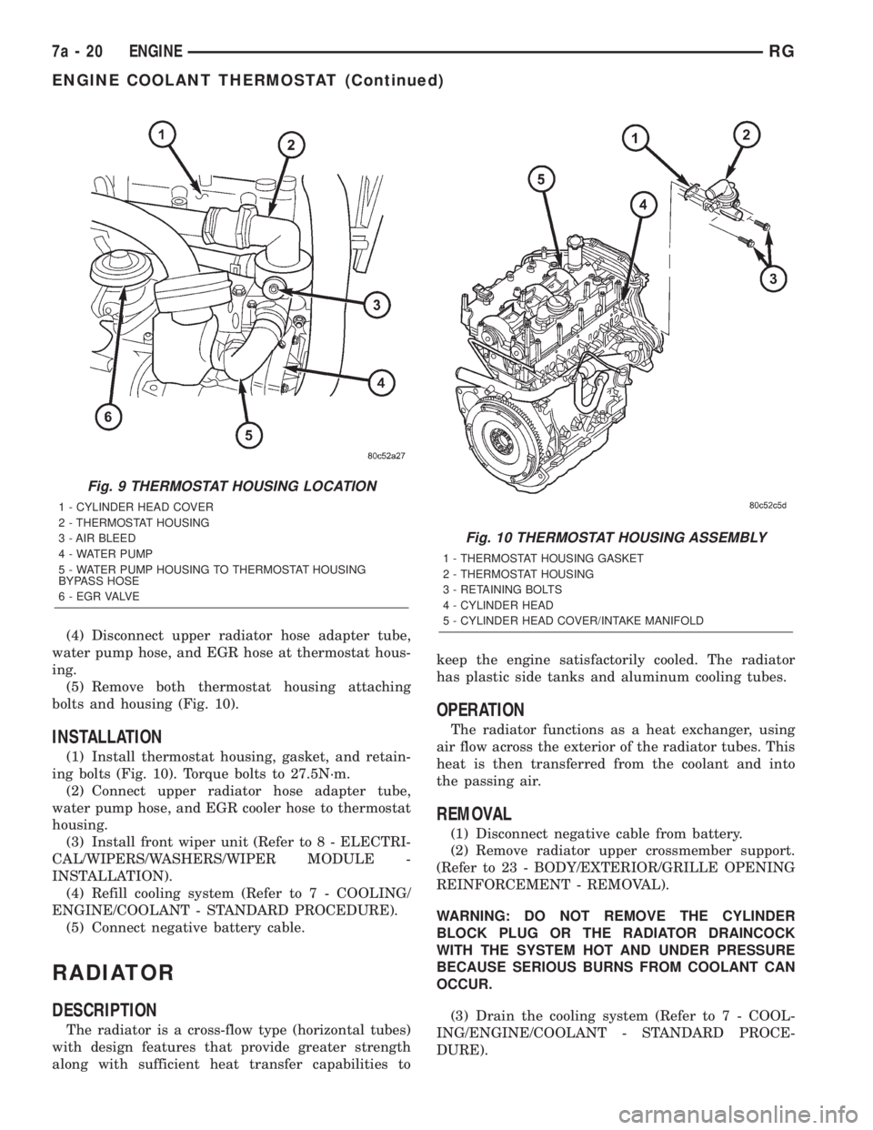
of coolant flow to the radiator (Fig. 9).
OPERATION
The thermostat starts to open at 80ÉC (176ÉF).
Above this temperature, coolant is allowed to flow to
the radiator. This provides quicker engine warmup
and overall temperature control.
The same thermostat is used for winter and sum-
mer seasons. An engine should not be operated with-
out a thermostat, except for servicing or testing.
Operating without a thermostat causes other prob-
lems. These are: longer engine warmup time, unreli-
able warmup performance, increased exhaust
emissions and crankcase condensation. This conden-
sation can result in sludge formation.
REMOVAL
NOTE: The thermostat is not serviced separately.
The thermostat and housing must be replaced as
an assembly.
(1) Disconnect negative battery cable.
(2) Drain cooling system (Refer to 7 - COOLING/
ENGINE/COOLANT - STANDARD PROCEDURE).
(3) Remove front wiper unit to gain access to ther-
mostat housing(Refer to 8 - ELECTRICAL/WIPERS/
WASHERS/WIPER MODULE - REMOVAL).
Fig. 8 COOLANT TEMPERATURE SENSOR
LOCATION
1 - EGR SOLENOID
2 - UPPER RADIATOR HOSE
3 - COOLANT TEMPERATURE SENSOR
4 - INTAKE MANIFOLD INLET
5 - INTAKE MANIFOLD/CYLINDER HEAD COVER
RGENGINE7a-19
Page 1794 of 4284
(4) Disconnect upper radiator hose adapter tube,
water pump hose, and EGR hose at thermostat hous-
ing.
(5) Remove both thermostat housing attaching
bolts and housing (Fig. 10).
INSTALLATION
(1) Install thermostat housing, gasket, and retain-
ing bolts (Fig. 10). Torque bolts to 27.5N´m.
(2) Connect upper radiator hose adapter tube,
water pump hose, and EGR cooler hose to thermostat
housing.
(3) Install front wiper unit (Refer to 8 - ELECTRI-
CAL/WIPERS/WASHERS/WIPER MODULE -
INSTALLATION).
(4) Refill cooling system (Refer to 7 - COOLING/
ENGINE/COOLANT - STANDARD PROCEDURE).
(5) Connect negative battery cable.
RADIATOR
DESCRIPTION
The radiator is a cross-flow type (horizontal tubes)
with design features that provide greater strength
along with sufficient heat transfer capabilities tokeep the engine satisfactorily cooled. The radiator
has plastic side tanks and aluminum cooling tubes.
OPERATION
The radiator functions as a heat exchanger, using
air flow across the exterior of the radiator tubes. This
heat is then transferred from the coolant and into
the passing air.
REMOVAL
(1) Disconnect negative cable from battery.
(2) Remove radiator upper crossmember support.
(Refer to 23 - BODY/EXTERIOR/GRILLE OPENING
REINFORCEMENT - REMOVAL).
WARNING: DO NOT REMOVE THE CYLINDER
BLOCK PLUG OR THE RADIATOR DRAINCOCK
WITH THE SYSTEM HOT AND UNDER PRESSURE
BECAUSE SERIOUS BURNS FROM COOLANT CAN
OCCUR.
(3) Drain the cooling system (Refer to 7 - COOL-
ING/ENGINE/COOLANT - STANDARD PROCE-
DURE).
Fig. 9 THERMOSTAT HOUSING LOCATION
1 - CYLINDER HEAD COVER
2 - THERMOSTAT HOUSING
3 - AIR BLEED
4 - WATER PUMP
5 - WATER PUMP HOUSING TO THERMOSTAT HOUSING
BYPASS HOSE
6 - E G R VA LV E
Fig. 10 THERMOSTAT HOUSING ASSEMBLY
1 - THERMOSTAT HOUSING GASKET
2 - THERMOSTAT HOUSING
3 - RETAINING BOLTS
4 - CYLINDER HEAD
5 - CYLINDER HEAD COVER/INTAKE MANIFOLD
7a - 20 ENGINERG
ENGINE COOLANT THERMOSTAT (Continued)
Page 1942 of 4284
LAMPS/LIGHTING - EXTERIOR
DESCRIPTION
LAMP SYSTEMS
RS vehicles use lighting on the interior and exte-
rior of the vehicle for illuminating and indicating
purposes. Lighting circuits are protected by fuses.
Lighting circuits require an overload protected power
source, on/off device, lamps and body ground to oper-
ate properly. Plastic lamps require a wire in the har-
ness to supply body ground to the lamp socket.
Replace sockets and bulbs that are corroded.
Some of the interior and exterior lighting functions
are governed by the Body Control Module. The head-
lamp, dome, and the door ajar switches provide sig-
nals to the Body Control Module. The Body Control
Module in turn sends a J1850 message to the Front
Control Module (FCM) to enable the necessary driv-
ers to set the required illumination configuration.
Wire connectors can make intermittent contact or
become corroded. Before coupling wire connectors,
inspect the terminals inside the connector. Male termi-
nals should not be bent or disengaged from the insu-
lator. Female terminals should not be sprung open or
disengaged from the insulator. Bent and sprung termi-
nals can be repaired using needle nose pliers and pick
tool. Corroded terminals appear chalky or green. Cor-
roded terminals should be replaced to avoid recur-
rence of the problem symptoms.
Begin electrical system failure diagnosis by testing
related fuses in the fuse block and intelligent power
module. Verify that bulbs are in good condition and
test continuity of the circuit ground. Refer to the
appropriate wiring information. The wiring informa-
tion includes wiring diagrams, proper wire and con-
nector repair procedures, details of wire harness
routing and retention, connector pin-out information
and location views for the various wire harness con-
nectors, splices and grounds.
AUTOMATIC HEADLAMP SYSTEM
The Automatic Headlamp system turns the instru-
mentation and exterior illumination lamps ON when
the ambient light levels are Night and OFF when
light levels are Day.
DAYTIME RUNNING LAMPS
Operating the high-beam headlamps at reduced
power provides daytime running lamps, which are
required on all new Canadian vehicles.
HEADLAMPS ON WITH WINDSHIELD WIPERS
For vehicles equipped with the Automatic Head-
lamp System, the instrumentation and exterior illu-
mination lamps will be turned ON when theheadlamp switch is in the AUTO position, RPM >
450 and the windshield wipers have been in the
intermittent, low or high mode of operation for more
than ten seconds. When the windshield wipers are
turned OFF the Body Control Module will determine
if the instrumentation and exterior illumination
lamps should remain ON base upon the current
ambient light level.
HEADLAMP SYSTEM
The configuration of the headlamp system of head-
lamps, park lamps and fog lamps is determined by
the BCM. The BCM determines the lighting configu-
ration as a result of the inputs from the ignition
switch, headlamp switch and multifunction switch. A
J1850 is transmitted from the BCM to the FCM to
enable the necessary drivers to set the illumination
configuration. Four wires are connected between the
headlamp switch and the BCM. The first wire con-
tains information regarding the position of the head-
lamp switch (Off, Automatic Headlamps, Automatic
Headlamp switch fog, Park with Fog, Head, or Head
with Fog Lamps). The second wire contains informa-
tion regarding the position of the dimmer switch
(Dome Lamp, Daytime Brightness, Dimming Level or
Off). The third wire is a dedicated signal return
(ground) wire. The fourth wire provides power to the
front fog lamp indicator.
HEADLAMP TIME DELAY SYSTEM
The headlamp time delay system is controlled by
the Body Control Module (BCM) via a J1850 message
transmitted by the BCM to the FCM to turn off the
headlamps.
OPERATION
AUTOMATIC HEADLAMP SYSTEM
Automatic headlamps are controlled by the Body
Control Module (BCM). With the headlamp switch in
the AUTO position, the BCM will control the head-
lamp, parking, side marker, tail and instrumentation
lamps based on ambient light levels. Ambient light
levels are monitored by the BCM using the Day/
Night signal and Electrochromatic Mirror (ECM)
present from the Compass Mini Trip (CMTC) located
on the front windshield in front of the rear view mir-
ror (ECM). Ambient light readings are averaged to
limit cycling the lamps ON and OFF when passing
through areas with varying light levels. The auto-
matic headlamps will only function when the engine
is running with RPM > 450. When the headlamp
switch is in the AUTO position (Automatic mode), the
Headlamp Time Delay system will function when the
ignition switch is placed in any position other than
run/start.
8L - 2 LAMPS/LIGHTING - EXTERIORRS
Page 1977 of 4284
recall memory settings when the Driver 1 or Driver 2
push buttons of the memory switch on the driver side
front door trim panel are depressed.
²SOUND HORN ON LOCK?- The options
include Yes and No. The default is No. When Yes is
selected, a short horn chirp will provide an audible
confirmation when the RKE receiver recognizes a
valid Lock signal from an RKE transmitter. When No
is selected, no horn chirp will occur with the RKE
Lock event. This feature may be selected indepen-
dent of theFLASH LIGHTS WITH LOCKS?pro-
grammable feature.
²FLASH LIGHTS WITH LOCKS?- The options
include Yes and No. The default is Yes. When Yes is
selected, a single flash of the hazard warning lamps
will provide an optical confirmation when the RKE
receiver recognizes a valid Lock signal from an RKE
transmitter, and two flashes of the same lamps will
occur when the RKE receiver recognizes a valid
Unlock signal from an RKE transmitter. When No is
selected, no lamp flash will occur with the RKE Lock
or Unlock event. This feature may be selected inde-
pendent of theSOUND HORN ON LOCK?pro-
grammable feature.
²HEADLAMP DELAY =- The options include
Off, 30 Sec, 60 Sec, and 90 Sec. The default is 90 Sec.
When a time interval is selected, the headlamps will
remain on for that length of time when the head-
lamps are turned off after the ignition is turned off,
or if the Auto mode is selected on vehicles with the
Auto Headlamps option. When Off is selected, the
headlamp delay feature is disabled.
²HEADLAMPS ON WITH WIPERS?- This pro-
grammable feature only applies to vehicles equipped
with the optional Auto Headlamps. The options
include Yes and No. The default is No. When Yes is
selected, the headlamps will turn on automatically
when the windshield wipers are turned on. The head-
lamps will turn off when the wipers are turned off,
as long as the headlamp switch is in the Auto or Off
positions. When No is selected, the headlamps will
only turn on if manually selected or if the Auto mode
is selected and the outside ambient light levels dic-
tate that they should be on.
²POWER ACCESSORY DELAY?- The options
include Yes and No. The default is Yes. When No is
selected, the accessory powered components will turn
off automatically when the ignition key is turned off.
When Yes is selected, the accessory powered compo-
nents will remain on for 45 seconds when the igni-
tion key is turned off.
REMOVAL
(1) Disconnect and isolate the battery negative
cable.(2) Remove overhead console. Refer to Overhead
Console Removal and Installation in this section(Re-
fer to 8 - ELECTRICAL/OVERHEAD CONSOLE -
REMOVAL) .
(3) Remove the ten screws holding the EVIC mod-
ule in the overhead console.
(4) Remove EVIC module from console assembly.
INSTALLATION
(1) Position the EVIC module in the overhead con-
sole.
(2) Install the ten screws holding the EVIC module
in the overhead console.
(3) Install the overhead console. Refer to Overhead
Console Removal and Installation in this section.
(4) Connect the battery negative cable.
NOTE: If a new EVIC module has been installed, the
compass will have to be calibrated and the variance
set. Refer to Compass Variation Adjustment and
Compass Calibration in the Service Procedures sec-
tion of this group for the procedures.
COMPASS/MINI-TRIP
COMPUTER
DESCRIPTION
The Compass Mini-Trip Computer (CMTC) and
Compass Temperature (CT) computer are modules
located in the overhead console. Vehicles are
equipped with either the CMTC or the CT computers
not both. The CMTC is different in the fact that it is
equipped with the mini-trip feature. The CMTC, CT
consists of a electronic control module with a vacuum
fluorescent display (VFD) and function switches. The
CMTC, CT consists of a electronic module that dis-
plays compass, trip computer (CMTC only), and tem-
perature features. Actuating the STEP push button
(CMTC only) will cause the CMTC to change mode of
operation when ignition is ON. Actuating the STEP
push button (CMTC only) will cause the CMTC to
change mode of operation when ignition is ON.
Example:
²Average miles per gallon (ECO)
²Distance to empty (DTE)
²Instant miles per gallon (ECO)
²Trip odometer (ODO)
²Elapsed time (ET)
²Off
Actuating the C/T push button will cause the
CMTC, CT to change to Compass/Temperature dis-
play.
RSOVERHEAD CONSOLE8M-9
ELECTRONIC VEHICLE INFO CENTER (Continued)
Page 2075 of 4284
WIPERS/WASHERS
TABLE OF CONTENTS
page page
WIPERS/WASHERS
DESCRIPTION............................1
OPERATION.............................1
DIAGNOSIS AND TESTING..................2
FRONT WIPER SYSTEM..................2
REAR WIPER SYSTEM...................2
FRONT WIPER/WASHER SWITCH...........2
FAILED PARK SWITCH...................2
FRONT WIPER ARMS
REMOVAL...............................4
INSTALLATION............................4
ADJUSTMENTS...........................4
FRONT WIPER MOTOR
REMOVAL...............................5
INSTALLATION............................5
FRONT WIPER UNIT
REMOVAL...............................5
INSTALLATION............................6
REAR WIPER ARM
REMOVAL...............................6
INSTALLATION............................7
REAR WIPER MOTOR
REMOVAL...............................7INSTALLATION............................7
REAR WIPER/WASHER SWITCH
DESCRIPTION............................7
OPERATION.............................7
WASHER HOSES
REMOVAL...............................7
INSTALLATION............................8
WASHER RESERVOIR
REMOVAL...............................8
INSTALLATION............................8
WIPER BLADES
REMOVAL...............................9
CLEANING...............................9
INSTALLATION............................9
WIPER BLADE ELEMENTS
REMOVAL...............................9
INSTALLATION...........................10
WIPER LINKAGE
REMOVAL..............................10
INSTALLATION...........................10
WIPERS/WASHERS
DESCRIPTION
FRONT WIPER/WASHER SYSTEM
The windshield wipers can be operated with the
windshield wiper switch when the ignition switch is
in the RUN or ACCESSORY positions. The wind-
shield wiper system is protected by a 30 amp fuse (9)
located in the Power Distribution Center (PDC) part
of the Integrated Power Module (IPM) in the engine
compartment. The wiper/washer switch is integral to
the multi-function switch. It is a resistive MUX
switch that sends inputs to the BCM to operate the
wiper/washer system.
REAR WIPER/WASHER SYSTEM
The rear windshield wiper and washers can be
operated when the ignition switch is in the RUN or
ACCESSORY positions.
OPERATION
FRONT WIPER/WASHER SYSTEM
The windshield washer circuit is protected by a 9
amp PTC located in the Junction Block. The wiper
motor has permanent magnetic fields. The speeds are
determined by current flow to the appropriate set of
brushes inside the motor. The current flow is con-
trolled by the multi-function switch stalk mounted
wiper switch, high speed/low speed relays located in
the Power Distribution Center (PDC) part of the
Integrated Power Module (IPM) in the engine com-
partment. The speed sensitive intermittent wiper is
controlled by the Body Control Module (BCM). The
intermittent mode, with the vehicle traveling greater
than 10.4 mph, has a range of 0.5 to 18 seconds.
With the vehicle traveling less than 10.4 mph, and
the time delay is not adjusted, time delay doubles to
a range of 1 to 36 seconds. The wiper arms will park
at the base of the windshield just above the cowl
cover after the wiper switch is turned OFF.
RSWIPERS/WASHERS8R-1
Page 2076 of 4284
The windshield wiper motor and linkage is located
in an integral wiper unit at the rear of the engine
compartment. The wiper unit must be removed to
gain access to the wiper motor.
REAR WIPER/WASHER SYSTEM
When continuous rear wiper operation is required,
the Body Control Module (BCM) will provide ignition
ON voltage to the rear wiper motor. When the wiper
switch is turned OFF, the BCM provides circuit
ground to operate the motor until the wipe cycle is
complete and the wiper arm returns to the base of
the rear window.
When intermittent rear wiper mode is selected, the
wiper motor will cycle every 7 seconds. The intermit-
tent delay time is also adjusted based upon vehicle
speed. With the vehicle traveling greater at 50 mph,
the cycle changes to every 5 seconds. DIAGNOSIS
AND TESTING
DIAGNOSIS AND TESTING - FRONT WIPER
SYSTEM
The windshield wiper system operates in several
modes:
²Low and high speed normal wipe
²Speed sensitive intermittent wipe
²Wipe after wash
²Pulse wipe
²Park (switch OFF)
The windshield wiper circuits are continuously
monitored and controlled by the Body Control Mod-
ule (BCM). If a problem occurs in the electronic com-
ponents, wiring, switch (except integral motor park
switch) and wiper motor a Diagnostic Trouble Code
(DTC) will be stored in the BCM memory. DTC's can
be retrieved using a DRB IIItscan tool. Refer to the
proper Body Diagnostic Procedures manual for DTC
descriptions and retrieval information.
The windshield wiper park switch and circuit is
monitored by the BCM. The park switch and circuit
can be tested using the Wiper System Diagnosis
table.
DIAGNOSIS AND TESTING - REAR WIPER
SYSTEM
The rear window wiper system operates in several
modes:
²Continuous wipe
²Intermittent wipe
²Wash
²Wipe after wash
The windshield wiper circuits are continuously
monitored and controlled by the Body Control Mod-
ule (BCM). If a problem occurs in the electronic com-
ponents, wiring, switch (except integral motor parkswitch) and wiper motor a Diagnostic Trouble Code
(DTC) will be stored in the BCM memory. The
DTC(s) can be retrieved using a DRB IIItscan tool.
DIAGNOSIS AND TESTING - FRONT
WIPER/WASHER SWITCH
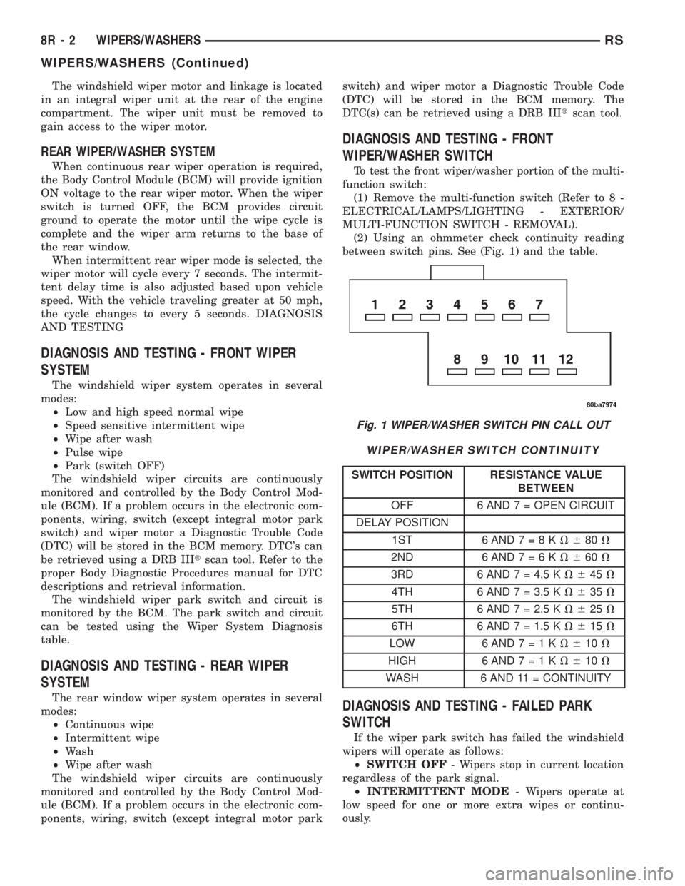
To test the front wiper/washer portion of the multi-
function switch:
(1) Remove the multi-function switch (Refer to 8 -
ELECTRICAL/LAMPS/LIGHTING - EXTERIOR/
MULTI-FUNCTION SWITCH - REMOVAL).
(2) Using an ohmmeter check continuity reading
between switch pins. See (Fig. 1) and the table.
WIPER/WASHER SWITCH CONTINUITY
SWITCH POSITION RESISTANCE VALUE
BETWEEN
OFF 6 AND 7 = OPEN CIRCUIT
DELAY POSITION
1ST 6AND7=8KV680V
2ND 6AND7=6KV660V
3RD 6 AND 7 = 4.5 KV645V
4TH 6 AND 7 = 3.5 KV635V
5TH 6 AND 7 = 2.5 KV625V
6TH 6 AND 7 = 1.5 KV615V
LOW 6AND7=1KV610V
HIGH 6 AND7=1KV610V
WASH 6 AND 11 = CONTINUITY
DIAGNOSIS AND TESTING - FAILED PARK
SWITCH
If the wiper park switch has failed the windshield
wipers will operate as follows:
²SWITCH OFF- Wipers stop in current location
regardless of the park signal.
²INTERMITTENT MODE- Wipers operate at
low speed for one or more extra wipes or continu-
ously.
Fig. 1 WIPER/WASHER SWITCH PIN CALL OUT
8R - 2 WIPERS/WASHERSRS
WIPERS/WASHERS (Continued)
Page 2077 of 4284
²LOW SPEED- Wipers operate at low speed.
²HIGH SPEED- Wipers operate at high speed.
²PULSE WIPE- Wipers will not operate.
²WIPE AFTER WASH- Wipers operate at low
speed in any mode setting. Wipers operate only whilewash button is depressed with switch in OFF mode,
wipers stop in mid-cycle when button is released.
The windshield wiper park switch and circuit is
monitored by the BCM. The park switch and circuit
can be tested using the table.
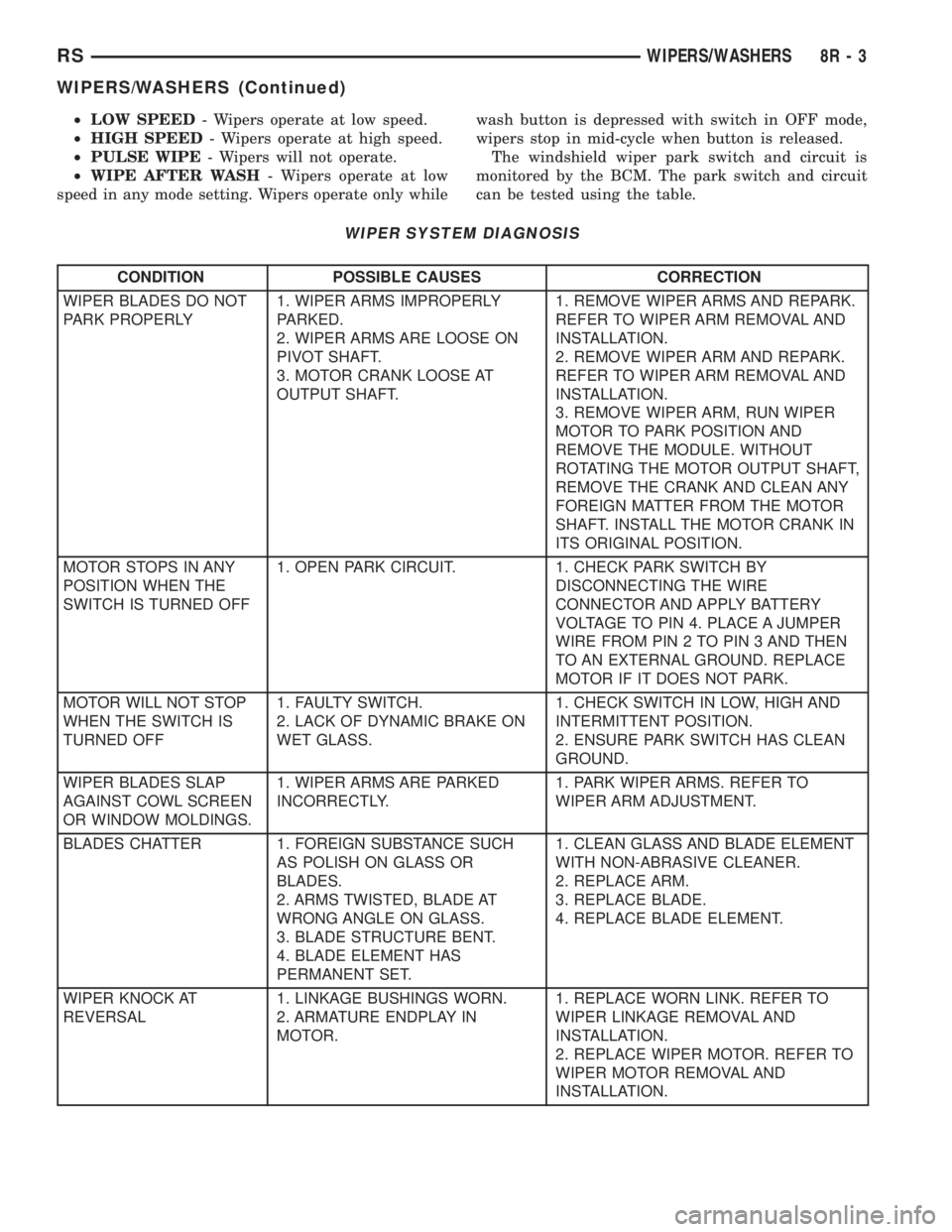
WIPER SYSTEM DIAGNOSIS
CONDITION POSSIBLE CAUSES CORRECTION
WIPER BLADES DO NOT
PARK PROPERLY1. WIPER ARMS IMPROPERLY
PARKED.
2. WIPER ARMS ARE LOOSE ON
PIVOT SHAFT.
3. MOTOR CRANK LOOSE AT
OUTPUT SHAFT.1. REMOVE WIPER ARMS AND REPARK.
REFER TO WIPER ARM REMOVAL AND
INSTALLATION.
2. REMOVE WIPER ARM AND REPARK.
REFER TO WIPER ARM REMOVAL AND
INSTALLATION.
3. REMOVE WIPER ARM, RUN WIPER
MOTOR TO PARK POSITION AND
REMOVE THE MODULE. WITHOUT
ROTATING THE MOTOR OUTPUT SHAFT,
REMOVE THE CRANK AND CLEAN ANY
FOREIGN MATTER FROM THE MOTOR
SHAFT. INSTALL THE MOTOR CRANK IN
ITS ORIGINAL POSITION.
MOTOR STOPS IN ANY
POSITION WHEN THE
SWITCH IS TURNED OFF1. OPEN PARK CIRCUIT. 1. CHECK PARK SWITCH BY
DISCONNECTING THE WIRE
CONNECTOR AND APPLY BATTERY
VOLTAGE TO PIN 4. PLACE A JUMPER
WIRE FROM PIN 2 TO PIN 3 AND THEN
TO AN EXTERNAL GROUND. REPLACE
MOTOR IF IT DOES NOT PARK.
MOTOR WILL NOT STOP
WHEN THE SWITCH IS
TURNED OFF1. FAULTY SWITCH.
2. LACK OF DYNAMIC BRAKE ON
WET GLASS.1. CHECK SWITCH IN LOW, HIGH AND
INTERMITTENT POSITION.
2. ENSURE PARK SWITCH HAS CLEAN
GROUND.
WIPER BLADES SLAP
AGAINST COWL SCREEN
OR WINDOW MOLDINGS.1. WIPER ARMS ARE PARKED
INCORRECTLY.1. PARK WIPER ARMS. REFER TO
WIPER ARM ADJUSTMENT.
BLADES CHATTER 1. FOREIGN SUBSTANCE SUCH
AS POLISH ON GLASS OR
BLADES.
2. ARMS TWISTED, BLADE AT
WRONG ANGLE ON GLASS.
3. BLADE STRUCTURE BENT.
4. BLADE ELEMENT HAS
PERMANENT SET.1. CLEAN GLASS AND BLADE ELEMENT
WITH NON-ABRASIVE CLEANER.
2. REPLACE ARM.
3. REPLACE BLADE.
4. REPLACE BLADE ELEMENT.
WIPER KNOCK AT
REVERSAL1. LINKAGE BUSHINGS WORN.
2. ARMATURE ENDPLAY IN
MOTOR.1. REPLACE WORN LINK. REFER TO
WIPER LINKAGE REMOVAL AND
INSTALLATION.
2. REPLACE WIPER MOTOR. REFER TO
WIPER MOTOR REMOVAL AND
INSTALLATION.
RSWIPERS/WASHERS8R-3
WIPERS/WASHERS (Continued)
Page 2078 of 4284
CONDITION POSSIBLE CAUSES CORRECTION
WIPER MOTOR WILL NOT
RUN1. BLOWN FUSE.
2. NEW FUSE BLOWS.
3. NEW FUSE BLOWS.
4. NO VOLTAGE AT MOTOR.
5. POOR GROUND.1. REPLACE FUSE, AND RUN SYSTEM.
2. CHECK FOR SHORT IN WIRING OR
SWITCH.
3. REPLACE FUSE, REMOVE MOTOR
CONNECTOR, TURN SWITCH ON, FUSE
DOES NOT BLOW, REPLACE MOTOR.
4. CHECK SWITCH AND WIRING
HARNESS. REFER TO WIRING
DIAGRAMS.
5. REPAIR GROUND WIRE CONNECTION
AS NECESSARY.
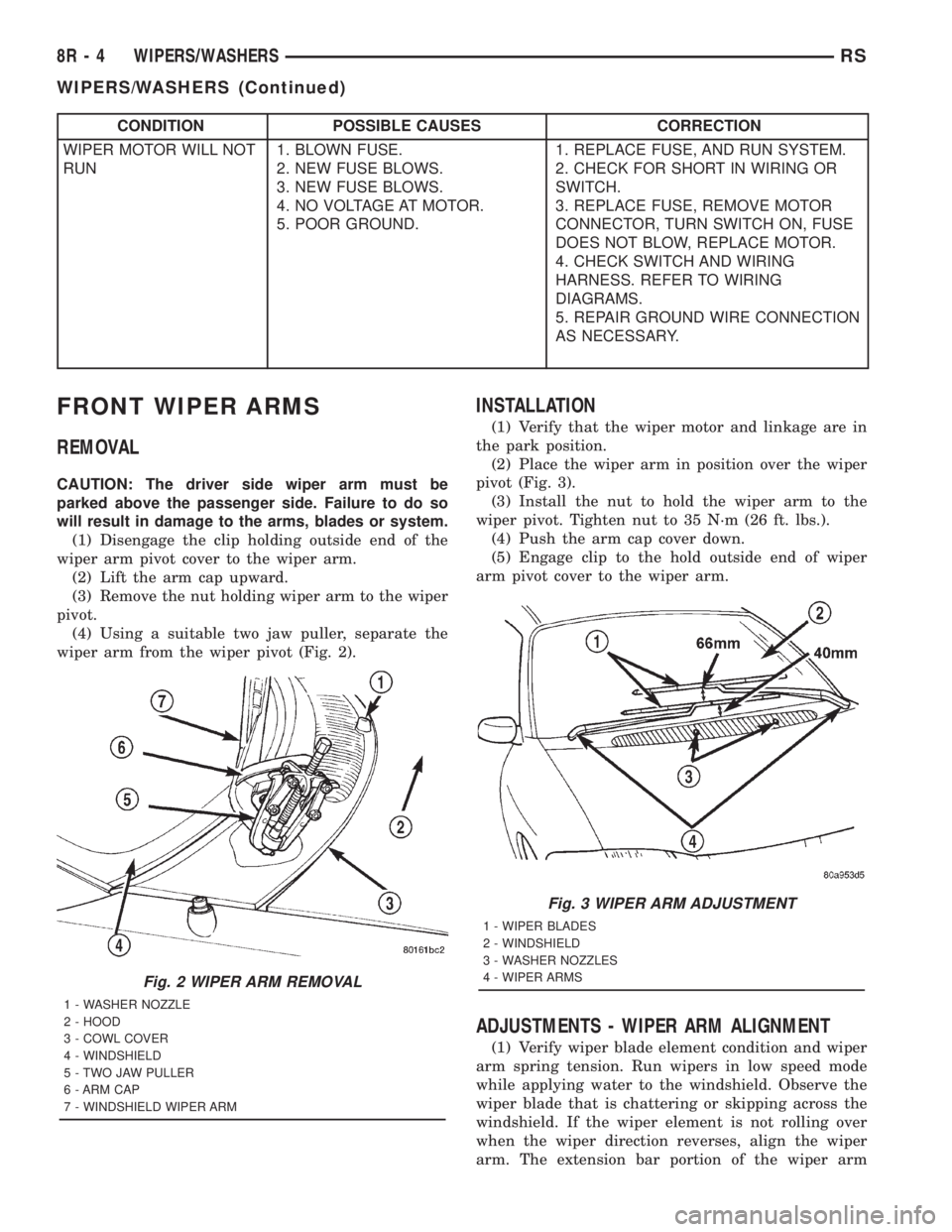
FRONT WIPER ARMS
REMOVAL
CAUTION: The driver side wiper arm must be
parked above the passenger side. Failure to do so
will result in damage to the arms, blades or system.
(1) Disengage the clip holding outside end of the
wiper arm pivot cover to the wiper arm.
(2) Lift the arm cap upward.
(3) Remove the nut holding wiper arm to the wiper
pivot.
(4) Using a suitable two jaw puller, separate the
wiper arm from the wiper pivot (Fig. 2).
INSTALLATION
(1) Verify that the wiper motor and linkage are in
the park position.
(2) Place the wiper arm in position over the wiper
pivot (Fig. 3).
(3) Install the nut to hold the wiper arm to the
wiper pivot. Tighten nut to 35 N´m (26 ft. lbs.).
(4) Push the arm cap cover down.
(5) Engage clip to the hold outside end of wiper
arm pivot cover to the wiper arm.
ADJUSTMENTS - WIPER ARM ALIGNMENT
(1) Verify wiper blade element condition and wiper
arm spring tension. Run wipers in low speed mode
while applying water to the windshield. Observe the
wiper blade that is chattering or skipping across the
windshield. If the wiper element is not rolling over
when the wiper direction reverses, align the wiper
arm. The extension bar portion of the wiper arm
Fig. 2 WIPER ARM REMOVAL
1 - WASHER NOZZLE
2 - HOOD
3 - COWL COVER
4 - WINDSHIELD
5 - TWO JAW PULLER
6 - ARM CAP
7 - WINDSHIELD WIPER ARM
Fig. 3 WIPER ARM ADJUSTMENT
1 - WIPER BLADES
2 - WINDSHIELD
3 - WASHER NOZZLES
4 - WIPER ARMS
8R - 4 WIPERS/WASHERSRS
WIPERS/WASHERS (Continued)