2001 CHRYSLER VOYAGER fold seats
[x] Cancel search: fold seatsPage 2056 of 4284
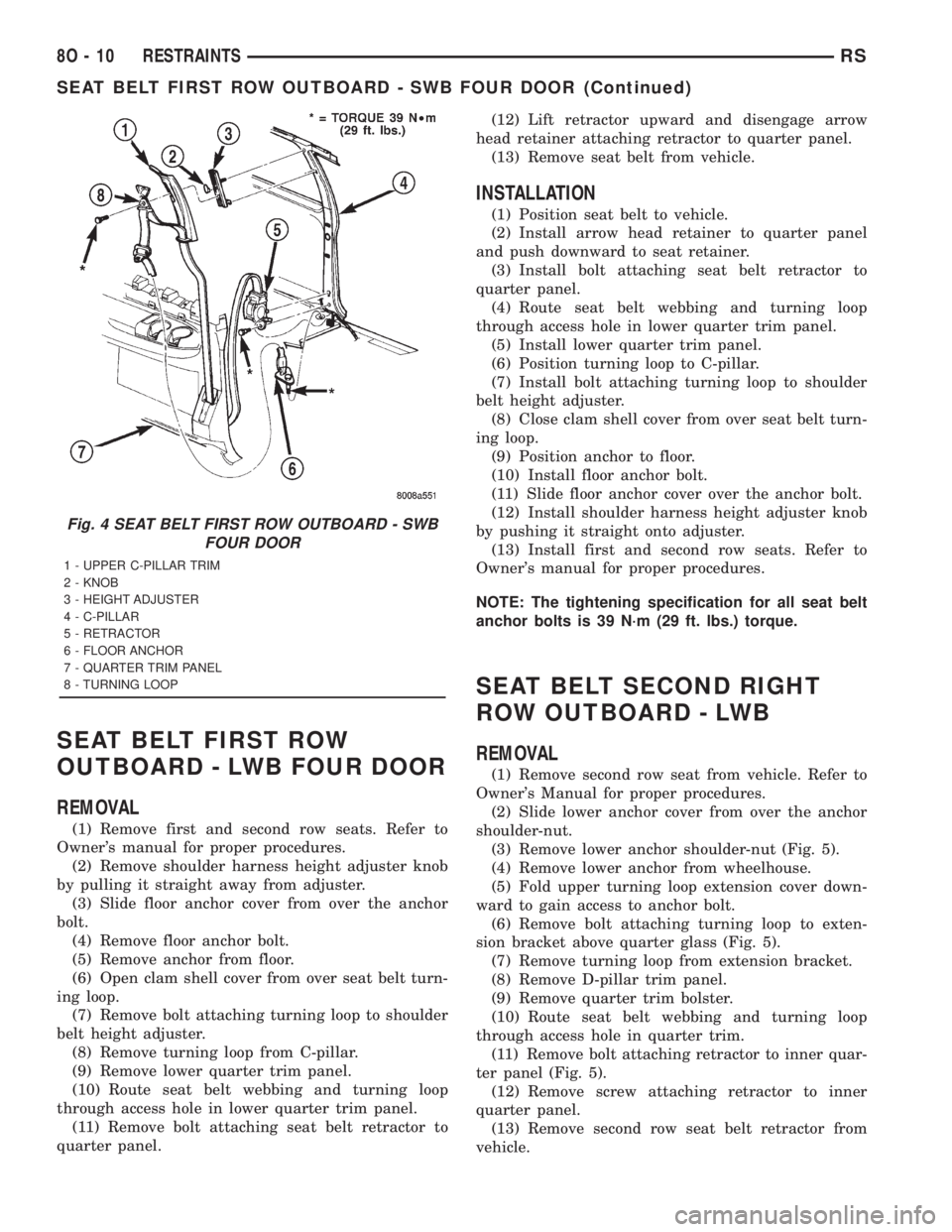
SEAT BELT FIRST ROW
OUTBOARD - LWB FOUR DOOR
REMOVAL
(1) Remove first and second row seats. Refer to
Owner's manual for proper procedures.
(2) Remove shoulder harness height adjuster knob
by pulling it straight away from adjuster.
(3) Slide floor anchor cover from over the anchor
bolt.
(4) Remove floor anchor bolt.
(5) Remove anchor from floor.
(6) Open clam shell cover from over seat belt turn-
ing loop.
(7) Remove bolt attaching turning loop to shoulder
belt height adjuster.
(8) Remove turning loop from C-pillar.
(9) Remove lower quarter trim panel.
(10) Route seat belt webbing and turning loop
through access hole in lower quarter trim panel.
(11) Remove bolt attaching seat belt retractor to
quarter panel.(12) Lift retractor upward and disengage arrow
head retainer attaching retractor to quarter panel.
(13) Remove seat belt from vehicle.
INSTALLATION
(1) Position seat belt to vehicle.
(2) Install arrow head retainer to quarter panel
and push downward to seat retainer.
(3) Install bolt attaching seat belt retractor to
quarter panel.
(4) Route seat belt webbing and turning loop
through access hole in lower quarter trim panel.
(5) Install lower quarter trim panel.
(6) Position turning loop to C-pillar.
(7) Install bolt attaching turning loop to shoulder
belt height adjuster.
(8) Close clam shell cover from over seat belt turn-
ing loop.
(9) Position anchor to floor.
(10) Install floor anchor bolt.
(11) Slide floor anchor cover over the anchor bolt.
(12) Install shoulder harness height adjuster knob
by pushing it straight onto adjuster.
(13) Install first and second row seats. Refer to
Owner's manual for proper procedures.
NOTE: The tightening specification for all seat belt
anchor bolts is 39 N´m (29 ft. lbs.) torque.
SEAT BELT SECOND RIGHT
ROW OUTBOARD - LWB
REMOVAL
(1) Remove second row seat from vehicle. Refer to
Owner's Manual for proper procedures.
(2) Slide lower anchor cover from over the anchor
shoulder-nut.
(3) Remove lower anchor shoulder-nut (Fig. 5).
(4) Remove lower anchor from wheelhouse.
(5) Fold upper turning loop extension cover down-
ward to gain access to anchor bolt.
(6) Remove bolt attaching turning loop to exten-
sion bracket above quarter glass (Fig. 5).
(7) Remove turning loop from extension bracket.
(8) Remove D-pillar trim panel.
(9) Remove quarter trim bolster.
(10) Route seat belt webbing and turning loop
through access hole in quarter trim.
(11) Remove bolt attaching retractor to inner quar-
ter panel (Fig. 5).
(12) Remove screw attaching retractor to inner
quarter panel.
(13) Remove second row seat belt retractor from
vehicle.
Fig. 4 SEAT BELT FIRST ROW OUTBOARD - SWB
FOUR DOOR
1 - UPPER C-PILLAR TRIM
2 - KNOB
3 - HEIGHT ADJUSTER
4 - C-PILLAR
5 - RETRACTOR
6 - FLOOR ANCHOR
7 - QUARTER TRIM PANEL
8 - TURNING LOOP
8O - 10 RESTRAINTSRS
SEAT BELT FIRST ROW OUTBOARD - SWB FOUR DOOR (Continued)
Page 2654 of 4284
(3) Apply MopartEngine RTV GEN II at the
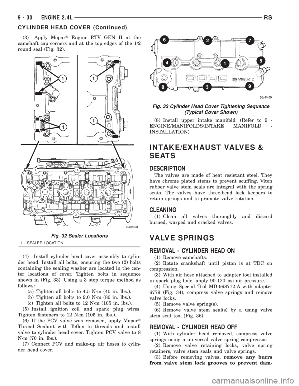
camshaft cap corners and at the top edges of the 1/2
round seal (Fig. 32).
(4) Install cylinder head cover assembly to cylin-
der head. Install all bolts, ensuring the two (2) bolts
containing the sealing washer are located in the cen-
ter locations of cover. Tighten bolts in sequence
shown in (Fig. 33). Using a 3 step torque method as
follows:
(a) Tighten all bolts to 4.5 N´m (40 in. lbs.).
(b) Tighten all bolts to 9.0 N´m (80 in. lbs.).
(c) Tighten all bolts to 12 N´m (105 in. lbs.).
(5) Install ignition coil and spark plug wires.
Tighten fasteners to 12 N´m (105 in. lbs.).
(6) If the PCV valve was removed, apply Mopart
Thread Sealant with Teflon to threads and install
valve to cylinder head cover. Tighten PCV valve to 8
N´m (70 in. lbs.).
(7) Connect PCV and make-up air hoses to cylin-
der head cover.(8) Install upper intake manifold. (Refer to 9 -
ENGINE/MANIFOLDS/INTAKE MANIFOLD -
INSTALLATION)
INTAKE/EXHAUST VALVES &
SEATS
DESCRIPTION
The valves are made of heat resistant steel. They
have chrome plated stems to prevent scuffing. Viton
rubber valve stem seals are integral with the spring
seats. The valves have three-bead lock keepers to
retain springs and to promote valve rotation.
CLEANING
(1) Clean all valves thoroughly and discard
burned, warped and cracked valves.
VALVE SPRINGS
REMOVAL - CYLINDER HEAD ON
(1) Remove camshafts.
(2) Rotate crankshaft until piston is at TDC on
compression.
(3) With air hose attached to adapter tool installed
in spark plug hole, apply 90-120 psi air pressure.
(4) Using Special Tool MD-998772-A with adapter
6779 (Fig. 34), compress valve springs and remove
valve locks.
(5) Remove valve spring(s).
(6) Remove valve stem seal(s) by a using valve
stem seal tool (Fig. 36).
REMOVAL - CYLINDER HEAD OFF
(1) With cylinder head removed, compress valve
springs using a universal valve spring compressor.
(2) Remove valve retaining locks, valve spring
retainers, valve stem seals and valve springs.
(3) Before removing valves,remove any burrs
from valve stem lock grooves to prevent dam-
Fig. 32 Sealer Locations
1 ± SEALER LOCATION
Fig. 33 Cylinder Head Cover Tightening Sequence
(Typical Cover Shown)
9 - 30 ENGINE 2.4LRS
CYLINDER HEAD COVER (Continued)
Page 3604 of 4284
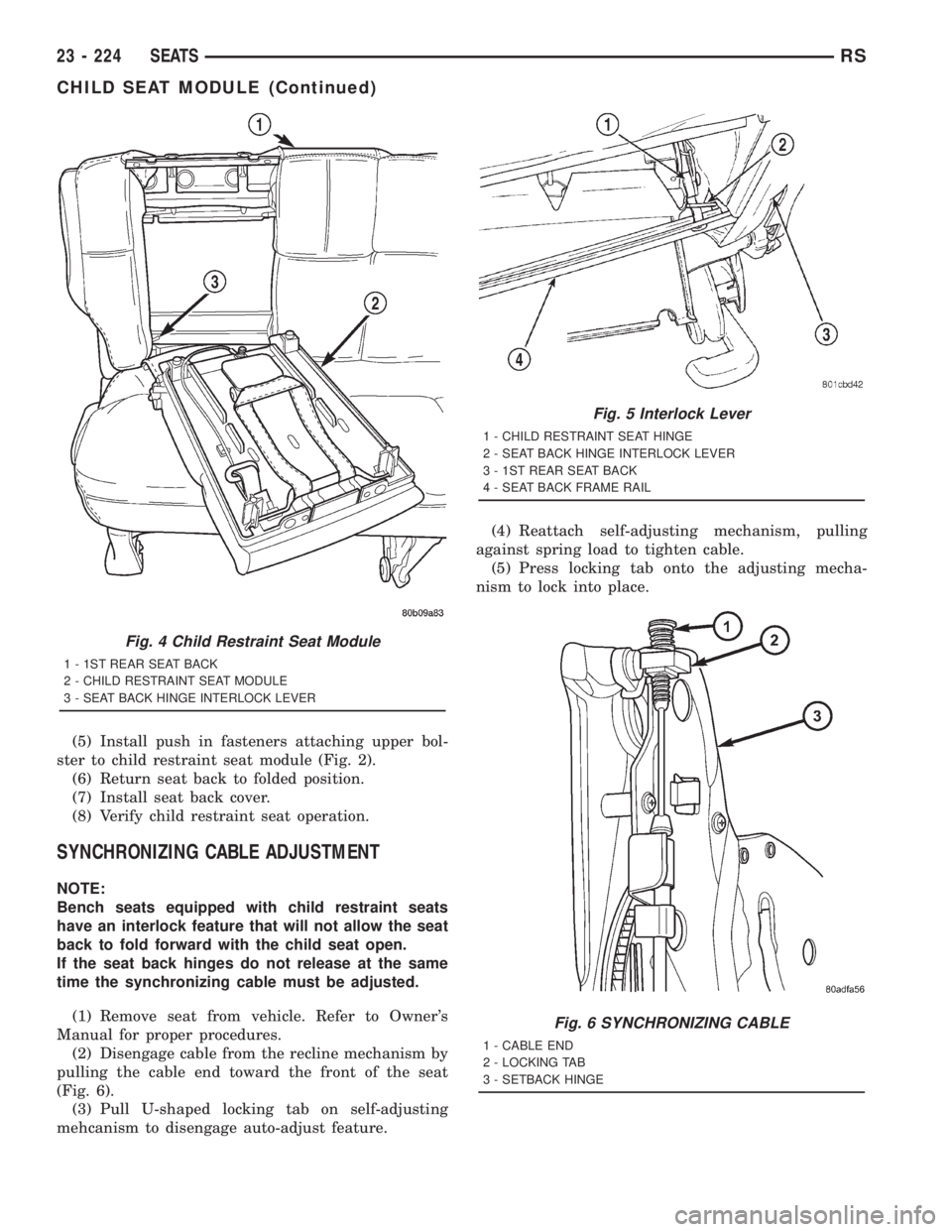
(5) Install push in fasteners attaching upper bol-
ster to child restraint seat module (Fig. 2).
(6) Return seat back to folded position.
(7) Install seat back cover.
(8) Verify child restraint seat operation.
SYNCHRONIZING CABLE ADJUSTMENT
NOTE:
Bench seats equipped with child restraint seats
have an interlock feature that will not allow the seat
back to fold forward with the child seat open.
If the seat back hinges do not release at the same
time the synchronizing cable must be adjusted.
(1) Remove seat from vehicle. Refer to Owner's
Manual for proper procedures.
(2) Disengage cable from the recline mechanism by
pulling the cable end toward the front of the seat
(Fig. 6).
(3) Pull U-shaped locking tab on self-adjusting
mehcanism to disengage auto-adjust feature.(4) Reattach self-adjusting mechanism, pulling
against spring load to tighten cable.
(5) Press locking tab onto the adjusting mecha-
nism to lock into place.
Fig. 4 Child Restraint Seat Module
1 - 1ST REAR SEAT BACK
2 - CHILD RESTRAINT SEAT MODULE
3 - SEAT BACK HINGE INTERLOCK LEVER
Fig. 5 Interlock Lever
1 - CHILD RESTRAINT SEAT HINGE
2 - SEAT BACK HINGE INTERLOCK LEVER
3 - 1ST REAR SEAT BACK
4 - SEAT BACK FRAME RAIL
Fig. 6 SYNCHRONIZING CABLE
1 - CABLE END
2 - LOCKING TAB
3 - SETBACK HINGE
23 - 224 SEATSRS
CHILD SEAT MODULE (Continued)
Page 3614 of 4284
QUAD BUCKET SEAT SIDE
SHIELD - NO CUP HOLDER
REMOVAL
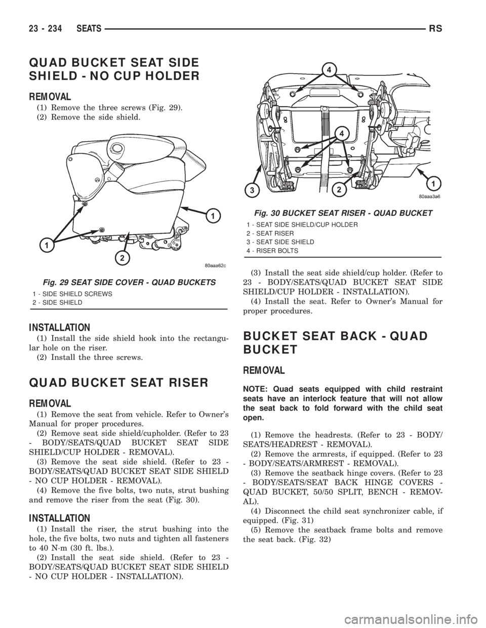
(1) Remove the three screws (Fig. 29).
(2) Remove the side shield.
INSTALLATION
(1) Install the side shield hook into the rectangu-
lar hole on the riser.
(2) Install the three screws.
QUAD BUCKET SEAT RISER
REMOVAL
(1) Remove the seat from vehicle. Refer to Owner's
Manual for proper procedures.
(2) Remove seat side shield/cupholder. (Refer to 23
- BODY/SEATS/QUAD BUCKET SEAT SIDE
SHIELD/CUP HOLDER - REMOVAL).
(3) Remove the seat side shield. (Refer to 23 -
BODY/SEATS/QUAD BUCKET SEAT SIDE SHIELD
- NO CUP HOLDER - REMOVAL).
(4) Remove the five bolts, two nuts, strut bushing
and remove the riser from the seat (Fig. 30).
INSTALLATION
(1) Install the riser, the strut bushing into the
hole, the five bolts, two nuts and tighten all fasteners
to 40 N´m (30 ft. lbs.).
(2) Install the seat side shield. (Refer to 23 -
BODY/SEATS/QUAD BUCKET SEAT SIDE SHIELD
- NO CUP HOLDER - INSTALLATION).(3) Install the seat side shield/cup holder. (Refer to
23 - BODY/SEATS/QUAD BUCKET SEAT SIDE
SHIELD/CUP HOLDER - INSTALLATION).
(4) Install the seat. Refer to Owner's Manual for
proper procedures.
BUCKET SEAT BACK - QUAD
BUCKET
REMOVAL
NOTE: Quad seats equipped with child restraint
seats have an interlock feature that will not allow
the seat back to fold forward with the child seat
open.
(1) Remove the headrests. (Refer to 23 - BODY/
SEATS/HEADREST - REMOVAL).
(2) Remove the armrests, if equipped. (Refer to 23
- BODY/SEATS/ARMREST - REMOVAL).
(3) Remove the seatback hinge covers. (Refer to 23
- BODY/SEATS/SEAT BACK HINGE COVERS -
QUAD BUCKET, 50/50 SPLIT, BENCH - REMOV-
AL).
(4) Disconnect the child seat synchronizer cable, if
equipped. (Fig. 31)
(5) Remove the seatback frame bolts and remove
the seat back. (Fig. 32)
Fig. 29 SEAT SIDE COVER - QUAD BUCKETS
1 - SIDE SHIELD SCREWS
2 - SIDE SHIELD
Fig. 30 BUCKET SEAT RISER - QUAD BUCKET
1 - SEAT SIDE SHIELD/CUP HOLDER
2 - SEAT RISER
3 - SEAT SIDE SHIELD
4 - RISER BOLTS
23 - 234 SEATSRS
Page 3618 of 4284
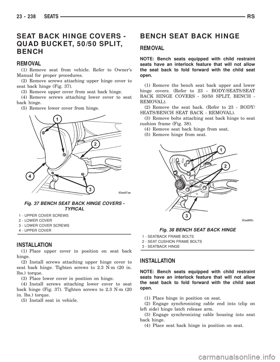
SEAT BACK HINGE COVERS -
QUAD BUCKET, 50/50 SPLIT,
BENCH
REMOVAL
(1) Remove seat from vehicle. Refer to Owner's
Manual for proper procedures.
(2) Remove screws attaching upper hinge cover to
seat back hinge (Fig. 37).
(3) Remove upper cover from seat back hinge.
(4) Remove screws attaching lower cover to seat
back hinge.
(5) Remove lower cover from hinge.
INSTALLATION
(1) Place upper cover in position on seat back
hinge.
(2) Install screws attaching upper hinge cover to
seat back hinge. Tighten screws to 2.3 N´m (20 in.
lbs.) torque.
(3) Place lower cover in position on hinge.
(4) Install screws attaching lower cover to seat
back hinge (Fig. 37). Tighten screws to 2.3 N´m (20
in. lbs.) torque.
(5) Install seat in vehicle.
BENCH SEAT BACK HINGE
REMOVAL
NOTE: Bench seats equipped with child restraint
seats have an interlock feature that will not allow
the seat back to fold forward with the child seat
open.
(1) Remove the bench seat back upper and lower
hinge covers. (Refer to 23 - BODY/SEATS/SEAT
BACK HINGE COVERS - 50/50 SPLIT, BENCH -
REMOVAL).
(2) Remove the seat back. (Refer to 23 - BODY/
SEATS/BENCH SEAT BACK - REMOVAL).
(3) Remove bolts attaching seat back hinge to seat
cushion frame (Fig. 38).
(4) Remove seat back hinge from seat.
(5) Remove hinge from seat.
INSTALLATION
NOTE: Bench seats equipped with child restraint
seats have an interlock feature that will not allow
the seat back to fold forward with the child seat
open.
(1) Place hinge in position on seat.
(2) Engage synchronizing cable end into (clip on
left side) hinge latch release arm.
(3) Engage synchronizing cable housing into seat
back hinge.
(4) Place seat back hinge in position on seat.
Fig. 37 BENCH SEAT BACK HINGE COVERS -
TYPICAL
1 - UPPER COVER SCREWS
2 - LOWER COVER
3 - LOWER COVER SCREWS
4 - UPPER COVER
Fig. 38 BENCH SEAT BACK HINGE
1 - SEATBACK FRAME BOLTS
2 - SEAT CUSHION FRAME BOLTS
3 - SEATBACK HINGE
23 - 238 SEATSRS
Page 3619 of 4284
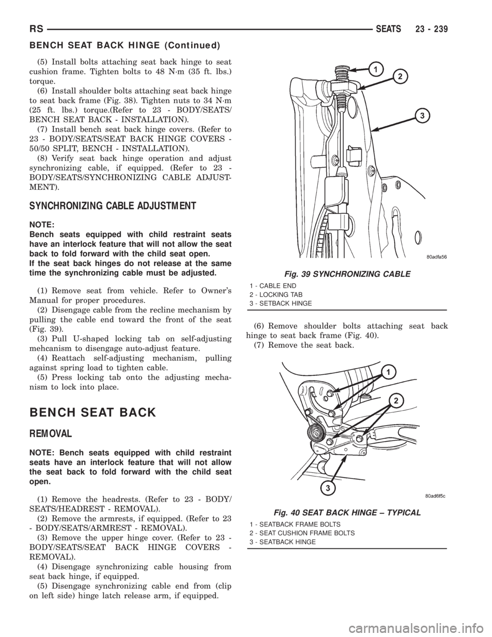
(5) Install bolts attaching seat back hinge to seat
cushion frame. Tighten bolts to 48 N´m (35 ft. lbs.)
torque.
(6) Install shoulder bolts attaching seat back hinge
to seat back frame (Fig. 38). Tighten nuts to 34 N´m
(25 ft. lbs.) torque.(Refer to 23 - BODY/SEATS/
BENCH SEAT BACK - INSTALLATION).
(7) Install bench seat back hinge covers. (Refer to
23 - BODY/SEATS/SEAT BACK HINGE COVERS -
50/50 SPLIT, BENCH - INSTALLATION).
(8) Verify seat back hinge operation and adjust
synchronizing cable, if equipped. (Refer to 23 -
BODY/SEATS/SYNCHRONIZING CABLE ADJUST-
MENT).
SYNCHRONIZING CABLE ADJUSTMENT
NOTE:
Bench seats equipped with child restraint seats
have an interlock feature that will not allow the seat
back to fold forward with the child seat open.
If the seat back hinges do not release at the same
time the synchronizing cable must be adjusted.
(1) Remove seat from vehicle. Refer to Owner's
Manual for proper procedures.
(2) Disengage cable from the recline mechanism by
pulling the cable end toward the front of the seat
(Fig. 39).
(3) Pull U-shaped locking tab on self-adjusting
mehcanism to disengage auto-adjust feature.
(4) Reattach self-adjusting mechanism, pulling
against spring load to tighten cable.
(5) Press locking tab onto the adjusting mecha-
nism to lock into place.
BENCH SEAT BACK
REMOVAL
NOTE: Bench seats equipped with child restraint
seats have an interlock feature that will not allow
the seat back to fold forward with the child seat
open.
(1) Remove the headrests. (Refer to 23 - BODY/
SEATS/HEADREST - REMOVAL).
(2) Remove the armrests, if equipped. (Refer to 23
- BODY/SEATS/ARMREST - REMOVAL).
(3) Remove the upper hinge cover. (Refer to 23 -
BODY/SEATS/SEAT BACK HINGE COVERS -
REMOVAL).
(4) Disengage synchronizing cable housing from
seat back hinge, if equipped.
(5) Disengage synchronizing cable end from (clip
on left side) hinge latch release arm, if equipped.(6) Remove shoulder bolts attaching seat back
hinge to seat back frame (Fig. 40).
(7) Remove the seat back.
Fig. 39 SYNCHRONIZING CABLE
1 - CABLE END
2 - LOCKING TAB
3 - SETBACK HINGE
Fig. 40 SEAT BACK HINGE ± TYPICAL
1 - SEATBACK FRAME BOLTS
2 - SEAT CUSHION FRAME BOLTS
3 - SEATBACK HINGE
RSSEATS23 - 239
BENCH SEAT BACK HINGE (Continued)
Page 3620 of 4284
INSTALLATION
NOTE: Bench seats equipped with child restraint
seats have an interlock feature that will not allow
the seat back to fold forward with the child seat
open.
(1) Install the seat back.
(2) Install the shoulder bolts attaching the seat
back hinge to the seat back frame and tighten to 34
N´m (25 ft. lbs.) torque.
(3) Connect the synchronizing cable end from (clip
on left side) hinge latch release arm, if equipped.
(4) Connect the synchronizing cable housing to the
seat back hinge, if equipped.
(5) Install the upper hinge cover. (Refer to 23 -
BODY/SEATS/SEAT BACK HINGE - INSTALLA-
TION).
(6) Install the armrests, if equipped. (Refer to 23 -
BODY/SEATS/ARMREST - INSTALLATION).
(7) Install the headrest sleeves. (Refer to 23 -
BODY/SEATS/HEADREST SLEEVE - INSTALLA-
TION).
(8) Adjust synchronizing cable, if equipped. (Refer
to 23 - BODY/SEATS/SYNCHRONIZING CABLE
ADJUSTMENT).
BENCH SEAT BACK COVER
REMOVAL
(1) Remove the bench seat back. (Refer to 23 -
BODY/SEATS/BENCH SEAT BACK - REMOVAL).
(2) Remove the bench seatback panel. (Refer to 23
- BODY/SEATS/BENCH SEATBACK PANEL -
REMOVAL).
(3) Disconnect the cover J-straps.
(4) Remove the seat back cover from the seat back
assembly.
INSTALLATION
(1) Install seat back cover onto the seat back
frame and cushion assembly.
(2) Connect the J-straps.
(3) Install the bench seatback panel. (Refer to 23 -
BODY/SEATS/BENCH SEATBACK PANEL -
INSTALLATION).
(4) Install the seat back. (Refer to 23 - BODY/
SEATS/BENCH SEAT BACK - INSTALLATION).
BENCH SEAT TRACK
REMOVAL
(1) Remove second row seat from vehicle. Refer to
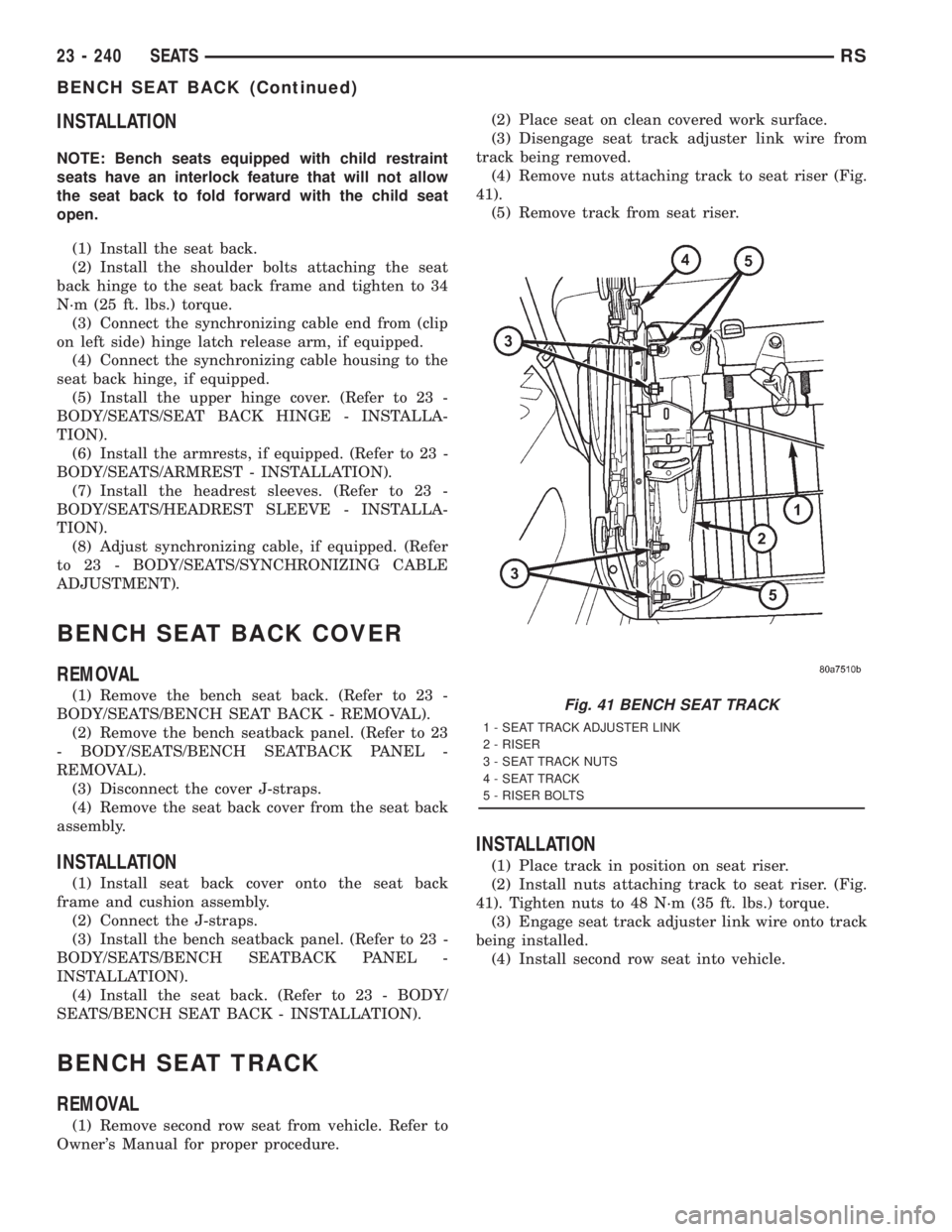
Owner's Manual for proper procedure.(2) Place seat on clean covered work surface.
(3) Disengage seat track adjuster link wire from
track being removed.
(4) Remove nuts attaching track to seat riser (Fig.
41).
(5) Remove track from seat riser.
INSTALLATION
(1) Place track in position on seat riser.
(2) Install nuts attaching track to seat riser. (Fig.
41). Tighten nuts to 48 N´m (35 ft. lbs.) torque.
(3) Engage seat track adjuster link wire onto track
being installed.
(4) Install second row seat into vehicle.
Fig. 41 BENCH SEAT TRACK
1 - SEAT TRACK ADJUSTER LINK
2 - RISER
3 - SEAT TRACK NUTS
4 - SEAT TRACK
5 - RISER BOLTS
23 - 240 SEATSRS
BENCH SEAT BACK (Continued)
Page 3684 of 4284
DISTRIBUTION - REAR
TABLE OF CONTENTS
page page
AIR OUTLETS
DESCRIPTION...........................54
REMOVAL..............................54
INSTALLATION...........................54
A/C DISTRIBUTION DUCT
REMOVAL..............................55
INSTALLATION...........................55
BLOWER MOTOR
DESCRIPTION...........................55
OPERATION.............................55DIAGNOSIS AND TESTING.................56
BLOWER MOTOR......................56
REMOVAL..............................58
INSTALLATION...........................58
REAR HEATER-A/C HOUSING
REMOVAL..............................58
INSTALLATION...........................60
REAR HEATER DISTRIBUTION DUCT
REMOVAL..............................61
INSTALLATION...........................61
AIR OUTLETS
DESCRIPTION
Based upon the system mode selected, conditioned
air can exit the rear heater-A/C unit housing through
one or a combination of the two main housing out-
lets: air conditioner, or heater. Once the conditioned
air exits the unit housing, it is directed through
molded plastic ducts to the various outlets in the
vehicle interior. These outlets and their locations are
as follows:
²Floor Outlets- Three floor outlets with fixed
vanes are located in the right quarter trim panel,
near the floor. These outlets distribute air from the
rear heater distribution duct to the intermediate and
rear seat occupants. The floor outlets are integral to
the right quarter trim panel and, if faulty or dam-
aged, the quarter trim panel must be replaced.
²Overhead Outlets- Four (two right side and
two left side) fully adjustable outlets along the roof
rails distribute air from the rear A/C distribution
duct and the headliner ducts to the intermediate and
rear seat occupants. The headliner ducts are integral
to the headliner panel. Each overhead outlet is
housed in a headliner bezel. The two forward head-
liner bezels also feature a courtesy lamp, a fold-away
coat hook, and a fold-away assist handle. The over-
head outlets can be removed from the headliner
bezels individually for service replacement.
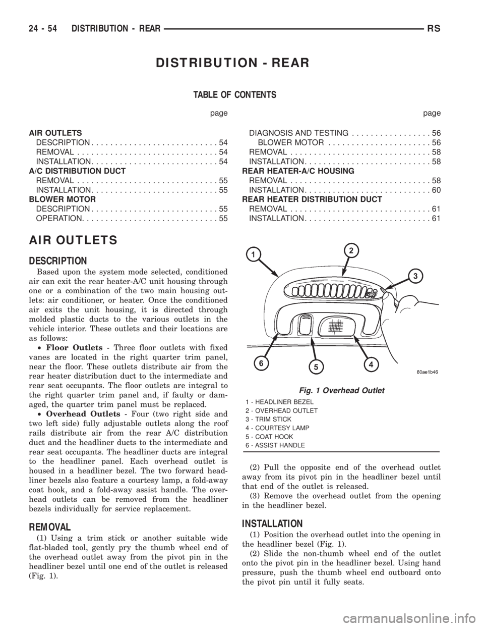
REMOVAL
(1) Using a trim stick or another suitable wide
flat-bladed tool, gently pry the thumb wheel end of
the overhead outlet away from the pivot pin in the
headliner bezel until one end of the outlet is released
(Fig. 1).(2) Pull the opposite end of the overhead outlet
away from its pivot pin in the headliner bezel until
that end of the outlet is released.
(3) Remove the overhead outlet from the opening
in the headliner bezel.
INSTALLATION
(1) Position the overhead outlet into the opening in
the headliner bezel (Fig. 1).
(2) Slide the non-thumb wheel end of the outlet
onto the pivot pin in the headliner bezel. Using hand
pressure, push the thumb wheel end outboard onto
the pivot pin until it fully seats.
Fig. 1 Overhead Outlet
1 - HEADLINER BEZEL
2 - OVERHEAD OUTLET
3 - TRIM STICK
4 - COURTESY LAMP
5 - COAT HOOK
6 - ASSIST HANDLE
24 - 54 DISTRIBUTION - REARRS