2001 CHRYSLER VOYAGER water pump
[x] Cancel search: water pumpPage 13 of 4284
TABLE OF CONTENTS - Continued
B1823 WATER PUMP CIRCUIT: OPEN.....................................323
B1823 WATER PUMP CIRCUIT: SHORT TO GROUND........................323
B1824 FAN SWITCH LINE SHORT TO GROUND............................324
CABIN HEATER CONTROL CIRCUIT OPEN (ACTIVE)........................325
CABIN HEATER CONTROL CIRCUIT SHORT TO BATTERY (ACTIVE)...........329
*CABIN HEATER INOPERABLE FROM A/C - HEATER MODULE...............332
CHIME
*CHIME INOPERATIVE..................................................334
*KEY IN IGNITION AND DRIVER'S DOOR OPEN CHIME NOT OPERATING
PROPERLY...........................................................336
*PROBLEM WITH THE HIGH VEHICLE SPEED WARNING CHIME.............337
COMMUNICATION
ATC MESSAGES NOT RECEIVED........................................338
AUDIO MESSAGES NOT RECEIVED......................................339
BCM, PCI BUS SHORTED TO BATTERY...................................340
BCM, PCI BUS SHORTED TO GROUND...................................340
FCM, PCI BUS SHORTED TO BATTERY...................................340
FCM, PCI BUS SHORTED TO GROUND...................................340
COUNTRY CODE NOT PROGRAMMED...................................342
FCM MESSAGES NOT RECEIVED........................................343
FCM, BCM COMMUNICATION FAULT.....................................344
FCM, HVAC COMMUNICATION FAULT....................................345
FCM, PCI INTERNAL FAULT.............................................346
FCM, PCM COMMUNICATION FAULT.....................................347
FCM, RADIO COMMUNICATION FAULT...................................348
FCM, TCM COMMUNICATION FAULT.....................................349
IGNITION MUX SWITCH INPUT OPEN....................................350
IGNITION MUX SWITCH INPUT SHORT...................................352
IGNITION RUN OUTPUT SHORT.........................................353
INTERNAL BCM FAILURE...............................................357
LEFT PSD MESSAGES NOT RECEIVED...................................358
LIFTGATE MODULE MESSAGES NOT RECEIVED...........................359
MIC MESSAGES NOT RECEIVED........................................360
MSM MESSAGES NOT RECEIVED.......................................361
NO PCI MESSAGES FROM CD CHANGER.................................362
ORC MESSAGES NOT RECEIVED........................................364
OTIS MESSAGES NOT RECEIVED.......................................365
PCI INTERNAL HARDWARE FAILURE.....................................366
PCM MESSAGES NOT RECEIVED........................................367
RADIO MEM MSG NOT RECEIVED.......................................368
RIGHT PSD MESSAGES NOT RECEIVED..................................369
RUN/START HARDWIRE INPUT FAILURE..................................370
SKIM MESSAGES NOT RECEIVED.......................................371
TCM MESSAGES NOT RECEIVED........................................372
*BUS +/- SIGNALS OPEN FROM AUTOMATIC TEMPERATURE CONTROL
MODULE.............................................................373
*BUS +/- SIGNALS OPEN FROM MEMORY SEAT/MIRROR MODULE...........375
*BUS +/- SIGNALS OPEN FROM SENTRY KEY IMMOBILIZER MODULE........377
*BUS +/- SIGNALS OPEN OR NO RESPONSE FROM BODY CONTROL
MODULE.............................................................379
*BUS +/- SIGNALS OPEN OR NO RESPONSE FROM HVAC..................381
x
Page 49 of 4284

The DCHA assembly consists of a:
²combustion air fan assembly
²burner housing
²burner insert
²control unit/heat exchanger
²combustion chamber
²dosing pump
3.10.2.2 COMBUSTION AIR FAN
The combustion air fan assembly includes the:
²combustion air fan
²combustion air fan inlet
²fuel supply inlet
The combustion air fan delivers the air required
for combustion from the combustion air inlet to the
burner insert.
3.10.2.3 BURNER HOUSING
The burner housing includes the:
²coolant inlet
²coolant outlet
²exhaust outlet
The burner housing accommodates the burner
insert and is combined with the control unit/heat
exchanger as an assembly.
3.10.2.4 BURNER INSERT
The burner insert includes the:
²combustion pipe fuel cross section
²glow plug/flame sensor
Inside the burner insert fuel is distributed across
the combustion pipe fuel cross section. Combustion
of the fuel/air mixture takes place within the com-
bustion pipe to heat the exchanger. The glow plug/
flame sensor located in the burner insert ignites the
fuel/air mixture during heater start up. After heater
start up, the glow plug/flame sensor operates in the
flame sensor function. The glow plug/flame sensor
designed as an electrical resistor is located in the
burner insert opposite the flame side.
3.10.2.5 CONTROL UNIT/HEAT
EXCHANGER
The control unit/heat exchanger includes the:
²control unit
²temperature sensor
²overheat protection
²heat exchanger
²connector terminal
The control unit controls and monitors combus-
tion operation. The control unit is ventilated bymeans of a ventilation hose routed from the com-
bustion air collector compartment of the burner.
The heat exchanger transfers the heat generated by
combustion to the coolant circuit. The control unit/
heat exchanger and the burner housing are an
assembly and must not be disassembled.
The temperature sensor senses the coolant tem-
perature in the heat exchanger as an electrical
resistance. This signal is sent to the control unit for
processing.
The overheat protection, controlled by the tem-
perature resistor, protects the heater against undue
operating temperatures. The overheat protection
will switch the heater off if the water temperature
exceeds 105ÉC (221ÉF).
3.10.2.6 DOSING PUMP
The dosing pump is a combined delivery, dosing,
and shut-off system for the fuel supply of the heater.
The dosing pump receives its supply of fuel from the
vehicle's fuel tank.
3.10.3 OPERATION
3.10.3.1 ACTIVATION
When the ignition is in Run, the FCM monitors
the PCI bus for the Cabin Heater Activation re-
quest. The A/C ± Heater Control Module initiates
this request only when all conditions for Cabin
Heater activation are favorable (see below). The
request carries the status bit that the FCM requires
to activate its Cabin Heater Assist Control Output.
This output is a low side driver (coming from FCM
pin 15) which supplies a ground signal to the Cabin
Heater (pin 5). When the Cabin Heater receives this
ground signal input, it interprets this as an activa-
tion signal. The FCM low side driver is also capable
of diagnostic sensing. The driver will sense an open
circuit when the driver is off, and will sense a short
to voltage when the driver is on. The FCM will set
DTCs for both of these types of faults.
The DCHA will activate only when the:
²engine is running.
²coolant temperature is below 66ÉC (151ÉF).
²fuel tank has greater than 1/8 of a tank of fuel.
²Power switch on the A/C ± Heater Control Module
is on.
²Blend Control on the A/C ± Heater Control Mod-
ule is set above 95% reheat.
²Front Control Module (FCM) sees the Cabin
Heater Activation request that is bussed from the
A/C ± Heater Control Module.
When the DCHA starting sequence begins, the
glow plug and the combustion air fan are activated.
After 30 seconds, the fuel dosing pump begins oper-
20
GENERAL INFORMATION
Page 352 of 4284

Symptom List:
B1823 WATER PUMP CIRCUIT: OPEN
B1823 WATER PUMP CIRCUIT: SHORT TO GROUND
Test Note: All symptoms listed above are diagnosed using the same tests.
The title for the tests will be B1823 WATER PUMP CIRCUIT:
OPEN.
When Monitored and Set Condition:
B1823 WATER PUMP CIRCUIT: OPEN
When Monitored: During DCHA activation and operation.
Set Condition: This fault is erroneous for this DCHA assembly.
B1823 WATER PUMP CIRCUIT: SHORT TO GROUND
When Monitored: During DCHA activation and operation.
Set Condition: This fault is erroneous for this DCHA assembly.
POSSIBLE CAUSES
DCHA CONTROL UNIT FAULT
TEST ACTION APPLICABILITY
1WARNING: DO NOT OPERATE THE DCHA IN AN ENCLOSED AREA SUCH
AS A GARAGE THAT DOES NOT HAVE EXHAUST VENTILATION FACILI-
TIES. ALWAYS VENT THE DCHA's EXHAUST WHEN OPERATING THE
DCHA. FAILURE TO FOLLOW THESE INSTRUCTIONS MAY RESULT IN
PERSONAL INJURY OR DEATH.
WARNING: ALLOW THE DCHA ASSEMBLY TO COOL BEFORE PERFORM-
ING A COMPONENT INSPECTION/REPAIR/REPLACEMENT. FAILURE TO
FOLLOW THESE INSTRUCTIONS MAY RESULT IN PERSONAL INJURY.
CAUTION: DO NOT PERFORM THIS TEST UNLESS DIRECTED HERE BY
THE CABIN HEATER PRE-TEST. ALWAYS PERFORM THE CABIN HEATER
PRE-TEST PRIOR TO PERFORMING ANY OTHER CABIN HEATER TEST
FOR THE RESULT TO BE VALID.
Turn the ignition off.
View repairAll
Repair
Replace the DCHA Heater Module in accordance with the Service
Information.
Perform CABIN HEATER VERIFICATION TEST - VER 1.
323
CABIN HEATER
Page 1219 of 4284
TABLE OF CONTENTS - Continued
A/C COMPRESSOR CLUTCH RELAY......................................242
ECM/PCM RELAY (DIESEL).............................................242
FUEL HEATER RELAY (DIESEL)..........................................242
LIFT PUMP RELAY (DIESEL).............................................242
STARTER MOTOR RELAY...............................................242
RADIATOR FAN NO. 1 (DIESEL) - GRAY 2 WAY.............................242
RADIATOR FAN NO. 2 (DIESEL) - GRAY 2 WAY.............................243
RADIATOR FAN RELAY NO. 1 (DIESEL) - BLUE 9 WAY......................243
RADIATOR FAN RELAY NO. 2 (DIESEL) - BLUE 9 WAY......................243
RADIATOR FAN RELAY NO. 3 (DIESEL) - BLUE 9 WAY......................243
RIGHT SPEED CONTROL SWITCH - WHITE 2 WAY.........................244
SENTRY KEY IMMOBILIZER MODULE - BLACK 6 WAY......................244
VEHICLE SPEED SENSOR (MTX/ATX) - BLACK 3 WAY......................244
WATER IN FUEL SENSOR (DIESEL) - BLACK 2 WAY........................244
10.0 SCHEMATIC DIAGRAMS................................................245
10.12001 RG 2.5L TURBO DIESEL......................................245
11.0 CHARTS AND GRAPHS................................................247
vi
Page 1494 of 4284
NOTE: Intentional tampering with emissions control
systems can result in civil penalties being assessed
against you.
GEAR LUBRICATION ± RATINGS
SAE ratings also apply to multiple grade gear
lubricants. In addition, API classification defines the
lubricants usage.
DESCRIPTION - ENGINE COOLANT
WARNING: ANTIFREEZE IS AN ETHYLENE GLYCOL
BASE COOLANT AND IS HARMFUL IF SWAL-
LOWED OR INHALED. IF SWALLOWED, DRINK
TWO GLASSES OF WATER AND INDUCE VOMIT-
ING. IF INHALED, MOVE TO FRESH AIR AREA.
SEEK MEDICAL ATTENTION IMMEDIATELY. DO NOT
STORE IN OPEN OR UNMARKED CONTAINERS.
WASH SKIN AND CLOTHING THOROUGHLY AFTER
COMING IN CONTACT WITH ETHYLENE GLYCOL.
KEEP OUT OF REACH OF CHILDREN. DISPOSE OF
GLYCOL BASE COOLANT PROPERLY, CONTACT
YOUR DEALER OR GOVERNMENT AGENCY FOR
LOCATION OF COLLECTION CENTER IN YOUR
AREA. DO NOT OPEN A COOLING SYSTEM WHEN
THE ENGINE IS AT OPERATING TEMPERATURE OR
HOT UNDER PRESSURE, PERSONAL INJURY CAN
RESULT. AVOID RADIATOR COOLING FAN WHEN
ENGINE COMPARTMENT RELATED SERVICE IS
PERFORMED, PERSONAL INJURY CAN RESULT.
CAUTION: Use of Propylene Glycol based coolants
is not recommended, as they provide less freeze
protection and less corrosion protection.
The cooling system is designed around the coolant.
The coolant must accept heat from engine metal, in
the cylinder head area near the exhaust valves and
engine block. Then coolant carries the heat to the
radiator where the tube/fin radiator can transfer the
heat to the air.
The use of aluminum cylinder blocks, cylinder
heads, and water pumps requires special corrosion
protection. MopartAntifreeze/Coolant, 5 Year/
100,000 Mile Formula (MS-9769), or the equivalent
ethylene glycol base coolant with organic corrosion
inhibitors (called HOAT, for Hybrid Organic Additive
Technology) is recommended. This coolant offers the
best engine cooling without corrosion when mixed
with 50% Ethylene Glycol and 50% distilled water to
obtain a freeze point of -37ÉC (-35ÉF). If it loses color
or becomes contaminated, drain, flush, and replace
with fresh properly mixed coolant solution.CAUTION: MoparTAntifreeze/Coolant, 5 Year/
100,000 Mile Formula (MS-9769) may not be mixed
with any other type of antifreeze. Doing so will
reduce the corrosion protection and may result in
premature water pump seal failure. If non-HOAT
coolant is introduced into the cooling system in an
emergency, it should be replaced with the specified
coolant as soon as possible.
DESCRIPTION - LUBRICANTS AND GREASES
When service is required, DaimlerChrysler Corpo-
ration recommends that only Mopartbrand parts,
lubricants and chemicals be used. Mopartprovides
the best engineered products for servicing
DaimlerChrysler Corporation vehicles.
Only lubricants bearing designations defined by
the following organization should be used to service a
Chrysler Corporation vehicle.
²Society of Automotive Engineers (SAE)
²American Petroleum Institute (API) (Fig. 6)
²National Lubricating Grease Institute (NLGI)
(Fig. 7)
SAE VISCOSITY RATING
An SAE viscosity grade is used to specify the vis-
cosity of engine oil. These are specified with a dual
SAE viscosity grade which indicates the cold-to-hot
temperature viscosity range. Example SAE 5W-30 =
multiple grade engine oil.
DaimlerChrysler Corporation only recommends
multiple grade engine oils.
API QUALITY CLASSIFICATION
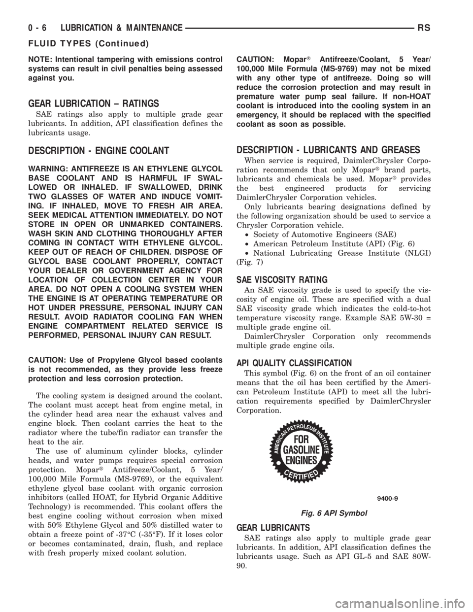
This symbol (Fig. 6) on the front of an oil container
means that the oil has been certified by the Ameri-
can Petroleum Institute (API) to meet all the lubri-
cation requirements specified by DaimlerChrysler
Corporation.
GEAR LUBRICANTS
SAE ratings also apply to multiple grade gear
lubricants. In addition, API classification defines the
lubricants usage. Such as API GL-5 and SAE 80W-
90.
Fig. 6 API Symbol
0 - 6 LUBRICATION & MAINTENANCERS
FLUID TYPES (Continued)
Page 1509 of 4284
LUBRICANTS AND GREASES
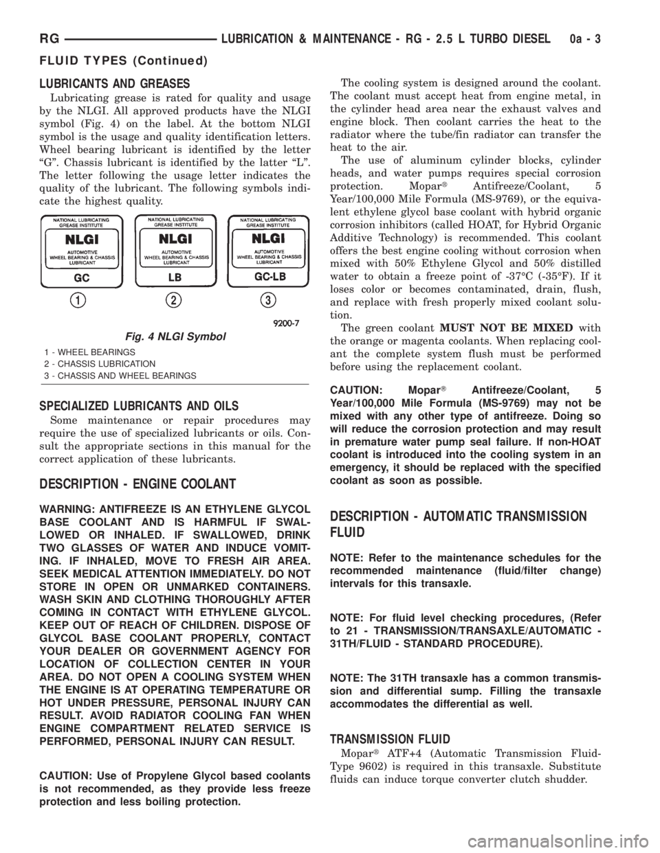
Lubricating grease is rated for quality and usage
by the NLGI. All approved products have the NLGI
symbol (Fig. 4) on the label. At the bottom NLGI
symbol is the usage and quality identification letters.
Wheel bearing lubricant is identified by the letter
ªGº. Chassis lubricant is identified by the latter ªLº.
The letter following the usage letter indicates the
quality of the lubricant. The following symbols indi-
cate the highest quality.
SPECIALIZED LUBRICANTS AND OILS
Some maintenance or repair procedures may
require the use of specialized lubricants or oils. Con-
sult the appropriate sections in this manual for the
correct application of these lubricants.
DESCRIPTION - ENGINE COOLANT
WARNING: ANTIFREEZE IS AN ETHYLENE GLYCOL
BASE COOLANT AND IS HARMFUL IF SWAL-
LOWED OR INHALED. IF SWALLOWED, DRINK
TWO GLASSES OF WATER AND INDUCE VOMIT-
ING. IF INHALED, MOVE TO FRESH AIR AREA.
SEEK MEDICAL ATTENTION IMMEDIATELY. DO NOT
STORE IN OPEN OR UNMARKED CONTAINERS.
WASH SKIN AND CLOTHING THOROUGHLY AFTER
COMING IN CONTACT WITH ETHYLENE GLYCOL.
KEEP OUT OF REACH OF CHILDREN. DISPOSE OF
GLYCOL BASE COOLANT PROPERLY, CONTACT
YOUR DEALER OR GOVERNMENT AGENCY FOR
LOCATION OF COLLECTION CENTER IN YOUR
AREA. DO NOT OPEN A COOLING SYSTEM WHEN
THE ENGINE IS AT OPERATING TEMPERATURE OR
HOT UNDER PRESSURE, PERSONAL INJURY CAN
RESULT. AVOID RADIATOR COOLING FAN WHEN
ENGINE COMPARTMENT RELATED SERVICE IS
PERFORMED, PERSONAL INJURY CAN RESULT.
CAUTION: Use of Propylene Glycol based coolants
is not recommended, as they provide less freeze
protection and less boiling protection.The cooling system is designed around the coolant.
The coolant must accept heat from engine metal, in
the cylinder head area near the exhaust valves and
engine block. Then coolant carries the heat to the
radiator where the tube/fin radiator can transfer the
heat to the air.
The use of aluminum cylinder blocks, cylinder
heads, and water pumps requires special corrosion
protection. MopartAntifreeze/Coolant, 5
Year/100,000 Mile Formula (MS-9769), or the equiva-
lent ethylene glycol base coolant with hybrid organic
corrosion inhibitors (called HOAT, for Hybrid Organic
Additive Technology) is recommended. This coolant
offers the best engine cooling without corrosion when
mixed with 50% Ethylene Glycol and 50% distilled
water to obtain a freeze point of -37ÉC (-35ÉF). If it
loses color or becomes contaminated, drain, flush,
and replace with fresh properly mixed coolant solu-
tion.
The green coolantMUST NOT BE MIXEDwith
the orange or magenta coolants. When replacing cool-
ant the complete system flush must be performed
before using the replacement coolant.
CAUTION: MoparTAntifreeze/Coolant, 5
Year/100,000 Mile Formula (MS-9769) may not be
mixed with any other type of antifreeze. Doing so
will reduce the corrosion protection and may result
in premature water pump seal failure. If non-HOAT
coolant is introduced into the cooling system in an
emergency, it should be replaced with the specified
coolant as soon as possible.DESCRIPTION - AUTOMATIC TRANSMISSION
FLUID
NOTE: Refer to the maintenance schedules for the
recommended maintenance (fluid/filter change)
intervals for this transaxle.
NOTE: For fluid level checking procedures, (Refer
to 21 - TRANSMISSION/TRANSAXLE/AUTOMATIC -
31TH/FLUID - STANDARD PROCEDURE).
NOTE: The 31TH transaxle has a common transmis-
sion and differential sump. Filling the transaxle
accommodates the differential as well.
TRANSMISSION FLUID
MopartATF+4 (Automatic Transmission Fluid-
Type 9602) is required in this transaxle. Substitute
fluids can induce torque converter clutch shudder.
Fig. 4 NLGI Symbol
1 - WHEEL BEARINGS
2 - CHASSIS LUBRICATION
3 - CHASSIS AND WHEEL BEARINGS
RGLUBRICATION & MAINTENANCE - RG - 2.5 L TURBO DIESEL0a-3
FLUID TYPES (Continued)
Page 1643 of 4284
CLEANING - DISC BRAKE SHOES
WARNING: DUST AND DIRT ACCUMULATING ON
BRAKE PARTS DURING NORMAL USE MAY CON-
TAIN ASBESTOS FIBERS FROM PRODUCTION OR
AFTERMARKET BRAKE LININGS. BREATHING
EXCESSIVE CONCENTRATIONS OF ASBESTOS
FIBERS CAN CAUSE SERIOUS BODILY HARM.
EXERCISE CARE WHEN SERVICING BRAKE
PARTS. DO NOT SAND OR GRIND BRAKE LINING
UNLESS EQUIPMENT USED IS DESIGNED TO CON-
TAIN THE DUST RESIDUE. DO NOT CLEAN BRAKE
PARTS WITH COMPRESSED AIR OR BY DRY
BRUSHING. CLEANING SHOULD BE DONE BY
DAMPENING THE BRAKE COMPONENTS WITH A
FINE MIST OF WATER, THEN WIPING THE BRAKE
COMPONENTS CLEAN WITH A DAMPENED CLOTH.
DISPOSE OF CLOTH AND ALL RESIDUE CONTAIN-
ING ASBESTOS FIBERS IN AN IMPERMEABLE
CONTAINER WITH THE APPROPRIATE LABEL. FOL-
LOW PRACTICES PRESCRIBED BY THE OCCUPA-
TIONAL SAFETY AND HEALTH ADMINISTRATION
(OSHA) AND THE ENVIRONMENTAL PROTECTION
AGENCY (EPA) FOR THE HANDLING, PROCESSING,
AND DISPOSING OF DUST OR DEBRIS THAT MAY
CONTAIN ASBESTOS FIBERS.
INSPECTION - DISC BRAKE SHOES
Visually inspect brake shoes (pads) for uneven lin-
ing wear. Also inspect for excessive lining deteriora-
tion. Check the clearance between the tips of the
wear indicators on the shoes (if equipped) and the
brake rotors.
If a visual inspection does not adequately deter-
mine the condition of the lining, a physical check will
be necessary. To check the amount of lining wear,
remove the disc brake shoes from the calipers.
Measure each brake shoe. The combined brake
shoe and its lining material thickness should be mea-
sured at its thinnest point.
²For front disc brake shoes, when a set of brake
shoes are worn to a thickness of approximately 7.95
mm (5/16 inch), they should be replaced.
²For rear disc brake shoes, when a set of brake
shoes are worn to a thickness of approximately 7.0
mm (9/32 inch), they should be replaced.
Replacebothdisc brake shoes (inboard and out-
board) on each caliper. It is necessary to replace the
shoes on the opposite side of the vehicle as well as
the shoes failing inspection.
If the brake shoe assemblies do not require
replacement, be sure to reinstall the brake shoes in
the original position they were remove from.
INSTALLATION - REAR DISC BRAKE SHOES
(1) Completely retract caliper piston back into pis-
ton bore of caliper assembly.
(2) Lubricate both adapter abutments where the
shoes contact with a liberal amount of MopartMul-
tipurpose Lubricant, or equivalent.
(3) If removed, install the brake rotor on the hub,
making sure it is squarely seated on the face of the
hub.
(4) Install the inboard brake shoe into the caliper
piston by firmly pressing it into the piston bore using
your thumbs. Be sure inboard brake shoe is posi-
tioned squarely against the face of the caliper piston.
(5) Install the outboard brake shoe on the disc
brake caliper. Be sure the outboard shoe is positioned
squarely against the outboard fingers of the caliper.
CAUTION: Use care when installing the caliper
assembly onto the adapter, so the caliper guide pin
bushings do not get damaged by the mounting
bosses.
(6) Carefully lower caliper and brake shoes over
rotor and onto adapter, reversing the removal proce-
dure (Fig. 16).
CAUTION: When installing the caliper guide pin
bolts extreme caution should be taken not to
crossthread the guide pin bolts.
(7) Install the caliper guide pin bolts. Tighten the
guide pin bolts to a torque of 35 N´m (26 ft. lbs.).
(8) Install the wheel and tire assembly. Tighten
the wheel mounting nuts in proper sequence until all
nuts are torqued to half specification. Then repeat
the tightening sequence to the full specified torque of
135 N´m (100 ft. lbs.).
(9) Remove jackstands or lower hoist.
CAUTION: Before moving vehicle, pump the brake
pedal several times to insure the vehicle has a firm
brake pedal to adequately stop the vehicle.
(10) Pump brake pedal several times to set brake
shoes to rotors.
(11) Check fluid level in reservoir.
(12) Road test the vehicle and make several stops
to wear off any foreign material on the brakes and to
seat the brake shoe linings.
RSBRAKES - BASE5-17
BRAKE PADS/SHOES - REAR DISC (Continued)
Page 1735 of 4284
COOLING
TABLE OF CONTENTS
page page
COOLING
DESCRIPTION............................1
OPERATION.............................1
DIAGNOSIS AND TESTING..................3
COOLING SYSTEM LEAK TEST.............3
COOLING SYSTEM FLOW CHECK..........3
COOLING SYSTEM AERATION.............3
COOLING SYSTEM DEAERATION...........3
STANDARD PROCEDURE...................4COOLING SYSTEM - DRAINING............4
COOLING SYSTEM - REFILLING............4
COOLANT - ADDING ADDITIONAL...........4
COOLANT LEVEL CHECK - ROUTINE........5
SPECIFICATIONS.........................6
SPECIAL TOOLS..........................6
ACCESSORY DRIVE.......................7
ENGINE................................13
TRANSMISSION.........................36
COOLING
DESCRIPTION - COOLING SYSTEM
The cooling system components consist of a radia-
tor, electric fan motors, shroud, pressure cap, thermo-
stat, transmission oil cooler, water pump, hoses,
clamps, coolant, and a coolant reserve system to com-
plete the circuit.
DESCRIPTION - HOSE CLAMPS
The cooling system uses spring type hose clamps.
If a spring type clamp replacement is necessary,
replace with the original Mopartequipment spring
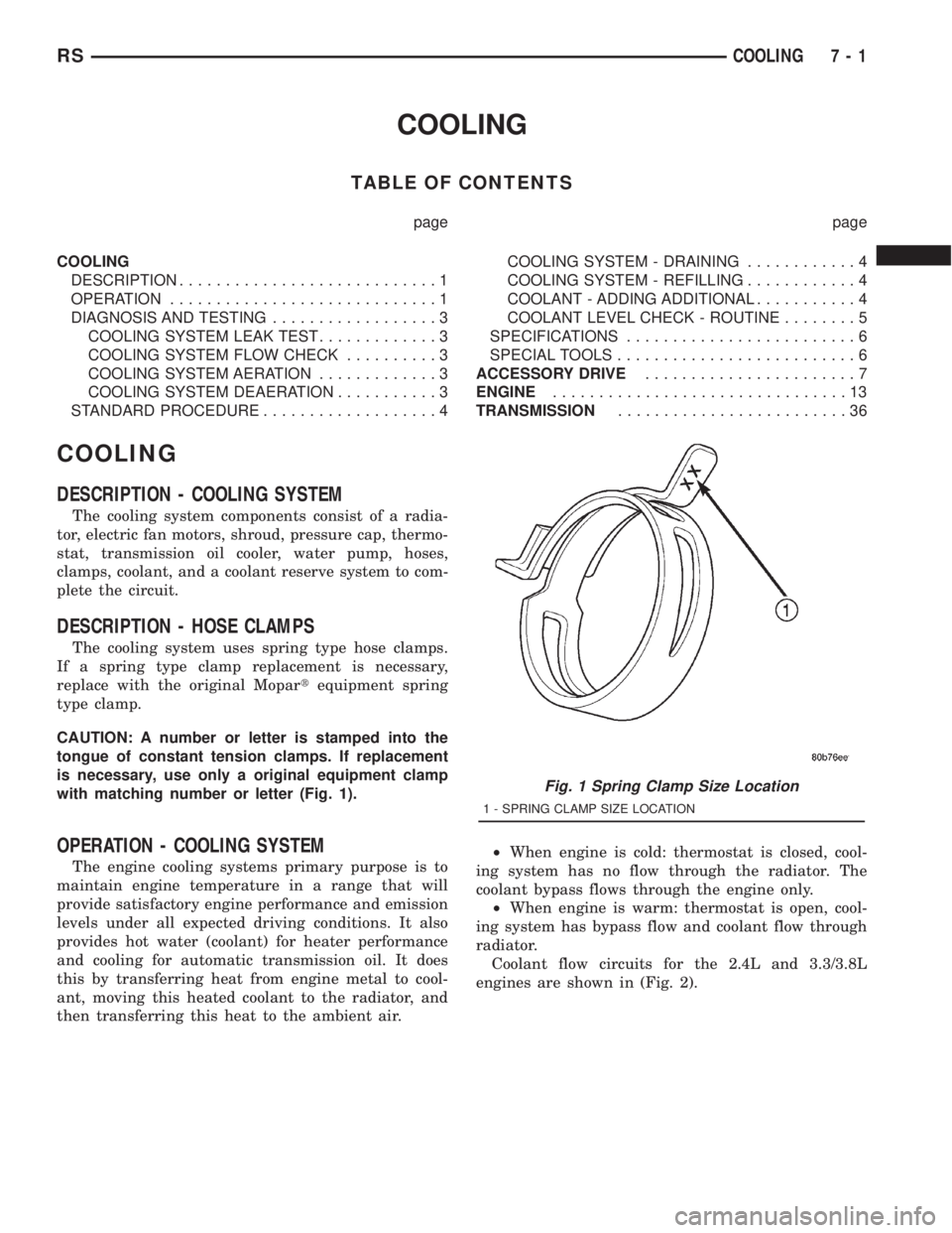
type clamp.
CAUTION: A number or letter is stamped into the
tongue of constant tension clamps. If replacement
is necessary, use only a original equipment clamp
with matching number or letter (Fig. 1).
OPERATION - COOLING SYSTEM
The engine cooling systems primary purpose is to
maintain engine temperature in a range that will
provide satisfactory engine performance and emission
levels under all expected driving conditions. It also
provides hot water (coolant) for heater performance
and cooling for automatic transmission oil. It does
this by transferring heat from engine metal to cool-
ant, moving this heated coolant to the radiator, and
then transferring this heat to the ambient air.²When engine is cold: thermostat is closed, cool-
ing system has no flow through the radiator. The
coolant bypass flows through the engine only.
²When engine is warm: thermostat is open, cool-
ing system has bypass flow and coolant flow through
radiator.
Coolant flow circuits for the 2.4L and 3.3/3.8L
engines are shown in (Fig. 2).
Fig. 1 Spring Clamp Size Location
1 - SPRING CLAMP SIZE LOCATION
RSCOOLING7-1