2001 CHRYSLER VOYAGER tow
[x] Cancel search: towPage 25 of 4284

TABLE OF CONTENTS - Continued
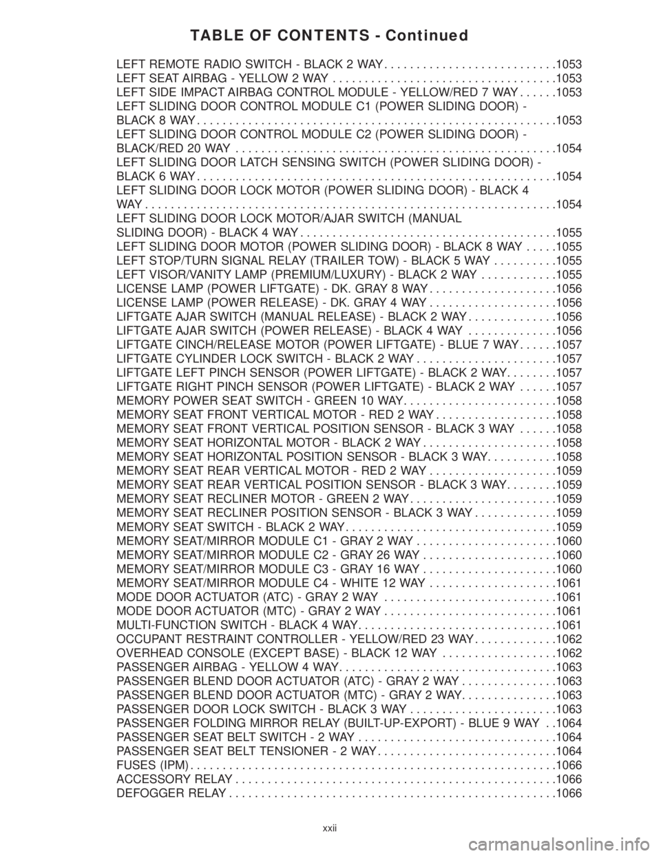
LEFT REMOTE RADIO SWITCH - BLACK 2 WAY...........................1053
LEFT SEAT AIRBAG - YELLOW 2 WAY...................................1053
LEFT SIDE IMPACT AIRBAG CONTROL MODULE - YELLOW/RED 7 WAY......1053
LEFT SLIDING DOOR CONTROL MODULE C1 (POWER SLIDING DOOR) -
BLACK 8 WAY........................................................1053
LEFT SLIDING DOOR CONTROL MODULE C2 (POWER SLIDING DOOR) -
BLACK/RED 20 WAY..................................................1054
LEFT SLIDING DOOR LATCH SENSING SWITCH (POWER SLIDING DOOR) -
BLACK 6 WAY........................................................1054
LEFT SLIDING DOOR LOCK MOTOR (POWER SLIDING DOOR) - BLACK 4
WAY................................................................1054
LEFT SLIDING DOOR LOCK MOTOR/AJAR SWITCH (MANUAL
SLIDING DOOR) - BLACK 4 WAY........................................1055
LEFT SLIDING DOOR MOTOR (POWER SLIDING DOOR) - BLACK 8 WAY.....1055
LEFT STOP/TURN SIGNAL RELAY (TRAILER TOW) - BLACK 5 WAY..........1055
LEFT VISOR/VANITY LAMP (PREMIUM/LUXURY) - BLACK 2 WAY............1055
LICENSE LAMP (POWER LIFTGATE) - DK. GRAY 8 WAY....................1056
LICENSE LAMP (POWER RELEASE) - DK. GRAY 4 WAY....................1056
LIFTGATE AJAR SWITCH (MANUAL RELEASE) - BLACK 2 WAY..............1056
LIFTGATE AJAR SWITCH (POWER RELEASE) - BLACK 4 WAY..............1056
LIFTGATE CINCH/RELEASE MOTOR (POWER LIFTGATE) - BLUE 7 WAY......1057
LIFTGATE CYLINDER LOCK SWITCH - BLACK 2 WAY......................1057
LIFTGATE LEFT PINCH SENSOR (POWER LIFTGATE) - BLACK 2 WAY........1057
LIFTGATE RIGHT PINCH SENSOR (POWER LIFTGATE) - BLACK 2 WAY......1057
MEMORY POWER SEAT SWITCH - GREEN 10 WAY........................1058
MEMORY SEAT FRONT VERTICAL MOTOR - RED 2 WAY...................1058
MEMORY SEAT FRONT VERTICAL POSITION SENSOR - BLACK 3 WAY......1058
MEMORY SEAT HORIZONTAL MOTOR - BLACK 2 WAY.....................1058
MEMORY SEAT HORIZONTAL POSITION SENSOR - BLACK 3 WAY...........1058
MEMORY SEAT REAR VERTICAL MOTOR - RED 2 WAY....................1059
MEMORY SEAT REAR VERTICAL POSITION SENSOR - BLACK 3 WAY........1059
MEMORY SEAT RECLINER MOTOR - GREEN 2 WAY.......................1059
MEMORY SEAT RECLINER POSITION SENSOR - BLACK 3 WAY.............1059
MEMORY SEAT SWITCH - BLACK 2 WAY.................................1059
MEMORY SEAT/MIRROR MODULE C1 - GRAY 2 WAY......................1060
MEMORY SEAT/MIRROR MODULE C2 - GRAY 26 WAY.....................1060
MEMORY SEAT/MIRROR MODULE C3 - GRAY 16 WAY.....................1060
MEMORY SEAT/MIRROR MODULE C4 - WHITE 12 WAY....................1061
MODE DOOR ACTUATOR (ATC) - GRAY 2 WAY...........................1061
MODE DOOR ACTUATOR (MTC) - GRAY 2 WAY...........................1061
MULTI-FUNCTION SWITCH - BLACK 4 WAY...............................1061
OCCUPANT RESTRAINT CONTROLLER - YELLOW/RED 23 WAY.............1062
OVERHEAD CONSOLE (EXCEPT BASE) - BLACK 12 WAY..................1062
PASSENGER AIRBAG - YELLOW 4 WAY..................................1063
PASSENGER BLEND DOOR ACTUATOR (ATC) - GRAY 2 WAY...............1063
PASSENGER BLEND DOOR ACTUATOR (MTC) - GRAY 2 WAY...............1063
PASSENGER DOOR LOCK SWITCH - BLACK 3 WAY.......................1063
PASSENGER FOLDING MIRROR RELAY (BUILT-UP-EXPORT) - BLUE 9 WAY . .1064
PASSENGER SEAT BELT SWITCH-2WAY...............................1064
PASSENGER SEAT BELT TENSIONER-2WAY............................1064
FUSES (IPM).........................................................1066
ACCESSORY RELAY..................................................1066
DEFOGGER RELAY...................................................1066
xxii
Page 567 of 4284

Symptom:
EVAPORATOR TEMPERATURE SENSOR CIRCUIT OPEN (ACTIVE)
- MANUAL A/C
When Monitored and Set Condition:
EVAPORATOR TEMPERATURE SENSOR CIRCUIT OPEN (ACTIVE) - MANUAL
A/C
When Monitored: With the ignition on.
Set Condition: This DTC will set if the Evaporator Temperature Sensor/sensor circuit is
open.
POSSIBLE CAUSES
EVAPORATOR TEMPERATURE SENSOR
EVAPORATOR TEMPERATURE SENSOR SIGNAL CIRCUIT OPEN
SENSOR GROUND CIRCUIT OPEN
A/C - HEATER CONTROL MODULE
TEST ACTION APPLICABILITY
1 Turn the ignition off.
Open the glove box door. Disconnect the glove box door roller latch from each side of
the glove box. Roll the glove box downward toward the floor.
Disconnect the in-line C202 harness connector.
Connect a jumper wire between the Evaporator Temperature Sensor Signal circuit
and the Sensor Ground circuit at the in-line C202 harness connector (HVAC side).
Turn the ignition on.
With the DRBIIItin Sensor Display, read the Evaporator Temperature Sensor
voltage.
Does the DRBIIItdisplay: 0.0 volts?All
Ye s®Check the wiring harness between the in-line C202 harness
connector (plenum side) and the Evap Temp Sensor for an open.
Repair as necessary. If Ok, replace the Evaporator Temperature
Sensor in accordance with the Service Information.
Perform BODY VERIFICATION TEST - VER 1.
No®Go To 2
538
HEATING & A/C
Page 568 of 4284

TEST ACTION APPLICABILITY
2 Turn the ignition off.
Disconnect the A/C - Heater Control Module C1 harness connector.
Open the glove box door. Disconnect the glove box door roller latch from each side of
the glove box. Roll the glove box downward toward the floor.
Disconnect the in-line C202 harness connector.
Measure the resistance of the Evaporator Temperature Sensor Signal circuit between
the A/C - Heater Control Module C1 harness connector and the in-line C202 harness
connector.
Is the resistance below 5.0 ohms?All
Ye s®Go To 3
No®Repair the Evaporator Temperature Sensor Signal circuit be-
tween the A/C - Heater Control Module C1 harness connector and
the in-line C202 harness connector (HVAC side) for an open.
Perform BODY VERIFICATION TEST - VER 1.
3 Turn the ignition off.
Disconnect the A/C - Heater Control Module C1 harness connector.
Open the glove box door. Disconnect the glove box door roller latch from each side of
the glove box. Roll the glove box downward toward the floor.
Disconnect the in-line C202 harness connector.
Measure the resistance of the Sensor Ground circuit between the A/C - Heater
Control Module C1 harness connector and the in-line C202 harness connector.
Is the resistance below 5.0 ohms?All
Ye s®Replace the A/C - Heater Control Module in accordance with the
Service Information.
Perform BODY VERIFICATION TEST - VER 1.
No®Repair the Sensor Ground circuit between the A/C - Heater
Control Module C1 harness connector and the in-line C202
harness connector (HVAC side) for an open.
Perform BODY VERIFICATION TEST - VER 1.
539
HEATING & A/C
EVAPORATOR TEMPERATURE SENSOR CIRCUIT OPEN (ACTIVE) -
MANUAL A/C Ð
Continued
Page 569 of 4284

Symptom:
EVAPORATOR TEMPERATURE SENSOR CIRCUIT SHORT (AC-
TIVE) - MANUAL A/C
When Monitored and Set Condition:
EVAPORATOR TEMPERATURE SENSOR CIRCUIT SHORT (ACTIVE) - MANUAL
A/C
When Monitored: With the ignition on.
Set Condition: This DTC will set if the Evaporator Temperature Sensor/sensor circuit is
shorted low.
POSSIBLE CAUSES
EVAPORATOR TEMPERATURE SENSOR
EVAPORATOR TEMPERATURE SENSOR SIGNAL CIRCUIT SHORT TO GROUND
EVAPORATOR TEMPERATURE SENSOR SIGNAL CIRCUIT SHORT TO SENSOR GROUND CIR-
CUIT
A/C - HEATER CONTROL MODULE
TEST ACTION APPLICABILITY
1 Turn the ignition off.
Open the glove box door. Disconnect the glove box door roller latch from each side of
the glove box. Roll the glove box downward toward the floor.
Disconnect the in-line C202 harness connector.
Turn the ignition on.
With the DRBIIItin Sensor Display, read the Evaporator Temperature Sensor
voltage.
Does the DRBIIItdisplay: 5.0 volts or greater?All
Ye s®Check the Evap Temp Sensor Signal circuit between the in-line
C202 harness connector (plenum side) and the Evap Temp Sensor
for a short to ground. Repair as necessary. If Ok, replace the
Evaporator Temperature Sensor in accordance with the Service
Info.
Perform BODY VERIFICATION TEST - VER 1.
No®Go To 2
540
HEATING & A/C
Page 570 of 4284

TEST ACTION APPLICABILITY
2 Turn the ignition off.
Disconnect the A/C - Heater Control Module C1 harness connector.
Open the glove box door. Disconnect the glove box door roller latch from each side of
the glove box. Roll the glove box downward toward the floor.
Disconnect the in-line C202 harness connector.
Measure the resistance between ground and the Evaporator Temperature Sensor
Signal circuit (HVAC side).
Is the resistance above 10K ohms?All
Ye s®Go To 3
No®Repair the Evaporator Temperature Sensor Signal circuit be-
tween the A/C - Heater Control Module C1 harness connector and
the in-line C202 harness connector (HVAC side) for a short to
ground.
Perform BODY VERIFICATION TEST - VER 1.
3 Turn the ignition off.
Disconnect the A/C - Heater Control Module C1 harness connector.
Open the glove box door. Disconnect the glove box door roller latch from each side of
the glove box. Roll the glove box downward toward the floor.
Disconnect the in-line C202 harness connector.
Measure the resistance between the Evaporator Temperature Sensor Signal circuit
and the Sensor Ground circuit (HVAC side).
Is the resistance above 10K ohms?All
Ye s®Replace the A/C - Heater Control Module in accordance with the
Service Information.
Perform BODY VERIFICATION TEST - VER 1.
No®Repair the Evaporator Temperature Sensor Signal circuit be-
tween the A/C - Heater Control Module C1 harness connector and
the in-line C202 harness connector (HVAC side) for a short to
Sensor Ground.
Perform BODY VERIFICATION TEST - VER 1.
541
HEATING & A/C
EVAPORATOR TEMPERATURE SENSOR CIRCUIT SHORT (ACTIVE) -
MANUAL A/C Ð
Continued
Page 1084 of 4284

LEFT SLIDING DOOR LOCK MOTOR/AJAR SWITCH (MANUAL SLIDING DOOR) - BLACK 4 WAYCAV CIRCUIT FUNCTION
1 P5 20BK/DB LEFT SLIDING DOOR UNLOCK DRIVER
2 P32 20BK/TN LEFT SLIDING DOOR LOCK DRIVER
3 G77 20BK/DG LEFT SLIDING DOOR AJAR SWITCH SENSE
4 Z77 20BK GROUND
LEFT SLIDING DOOR MOTOR (POWER SLIDING DOOR) - BLACK 8 WAYCAV CIRCUIT FUNCTION
1- -
2 Q71 20TN/VT LEFT DOOR MOTOR HALL EFFECT SUPPLY
3 Q69 16TN/OR LEFT SLIDING DOOR CLOSE DRIVER
4 Z163 18BK/TN GROUND
5 Q63 18OR/TN LEFT DOOR MOTOR CLUTCH DRIVER
6 Q67 16TN/BR LEFT SLIDING DOOR OPEN DRIVER
7 Z33 20BK/TN GROUND
8 Q73 20TN/YL LEFT DOOR MOTOR HALL EFFECT SIGNAL
LEFT STOP/TURN SIGNAL RELAY (TRAILER TOW) - BLACK 5 WAYCAV CIRCUIT FUNCTION
1 L50 18WT/TN PRIMARY BRAKE SWITCH SIGNAL
1 L50 18WT/TN PRIMARY BRAKE SWITCH SIGNAL
2 Z1 18BK/DG GROUND
2 Z1 18BK/DG GROUND
3 L73 18YL LEFT STOP SIGNAL
4 L63 18WT/DG LEFT REAR TURN SIGNAL DRIVER
4 L63 18WT/DG LEFT REAR TURN SIGNAL DRIVER
5 L615 18OR LEFT COMBINATION SIGNAL
LEFT VISOR/VANITY LAMP (PREMIUM/LUXURY) - BLACK 2 WAYCAV CIRCUIT FUNCTION
A Z327 20BK/OR GROUND
B M27 20YL/LB READING LAMP DRIVER
C
O
N
N
E
C
T
O
R
P
I
N
O
U
T
S
1055
CONNECTOR PINOUTS
Page 1158 of 4284

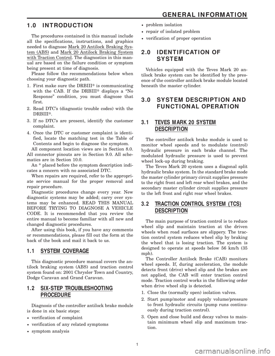
1.0 INTRODUCTION
The procedures contained in this manual include
all the specifications, instructions, and graphics
needed to diagnose Mark 20 Antilock Braking Sys-
tem (ABS) and Mark 20 Antilock Braking System
with Traction Control. The diagnostics in this man-
ual are based on the failure condition or symptom
being present at time of diagnosis.
Please follow the recommendations below when
choosing your diagnostic path.
1. First make sure the DRBIIItis communicating
with the CAB. If the DRBIIItdisplays a ªNo
Responseº condition, you must diagnose that
first.
2. Read DTC's (diagnostic trouble codes) with the
DRBIIIt.
3. If no DTC's are present, identify the customer
complaint.
4. Once the DTC or customer complaint is identi-
fied, locate the matching test in the Table of
Contents and begin to diagnose the symptom.
All component location views are in Section 8.0.
All connector pinouts are in Section 9.0. All sche-
matics are in Section 10.0.
An * placed before the symptom description indi-
cates a concern with no associated DTC.
When repairs are required, refer to the appropri-
ate service manual for the proper removal and
repair procedure.
Diagnostic procedures change every year. New
diagnostic systems may be added; carry over sys-
tems may be enhanced. READ THIS MANUAL
BEFORE TRYING TO DIAGNOSE A VEHICLE
CODE. It is recommended that you review the
entire manual to become familiar with all new and
changed diagnostic procedures.
After using this book, if you have any comments
or recommendations, please fill out the form at the
back of the book and mail it back to us.
1.1 SYSTEM COVERAGE
This diagnostic procedure manual covers the an-
tilock braking system (ABS) and traction control
system found on: 2001 Chrysler Town and Country,
Dodge Caravan and Grand Caravan.
1.2 SIX-STEP TROUBLESHOOTING
PROCEDURE
Diagnosis of the controller antilock brake module
is done in six basic steps:
²verification of complaint
²verification of any related symptoms
²symptom analysis
²problem isolation
²repair of isolated problem
²verification of proper operation
2.0 IDENTIFICATION OF
SYSTEM
Vehicles equipped with the Teves Mark 20 an-
tilock brake system can be identified by the pres-
ence of the controller antilock brake module located
beneath the master cylinder.
3.0 SYSTEM DESCRIPTION AND
FUNCTIONAL OPERATION
3.1 TEVES MARK 20 SYSTEM
DESCRIPTION
The controller antilock brake module is used to
monitor wheel speeds and to modulate (control)
hydraulic pressure in each brake channel. The
modulated hydraulic pressure is used to prevent
wheel lock-up during braking.
The Teves Mark 20 system uses a diagonal split
hydraulic brake system.
In the standard brake mode
the master cylinder primary circuit supplies pressure
to the right front and left rear wheel brakes, and the
secondary master cylinder circuit supplies pressure
to the left front and right rear wheel brakes.
3.2 TRACTION CONTROL SYSTEM (TCS)
DESCRIPTION
The main purpose of traction control is to reduce
wheel slip and maintain traction at the driven
wheels when road surfaces are slippery. The trac-
tion control system reduces wheel slip by braking
the wheel that is losing traction. The system is
designed to operate at speeds below 56 km/h (35
mph).
The Controller Antilock Brake (CAB) monitors
wheel speeds. If, during acceleration, the module
detects front (drive) wheel slip and the brakes are
not applied, the CAB will enter traction control
mode. Traction control works in the following order
when drive wheel slip is detected.
1. Close the (normally open) isolation valves.
2. Start pump/motor and supply volume/pressure
to front hydraulic circuits (pump runs continu-
ously during traction control).
3. Open and close build and decay valves to main-
tain minimum wheel slip and maximum trac-
tion.
1
GENERAL INFORMATION
Page 1470 of 4284

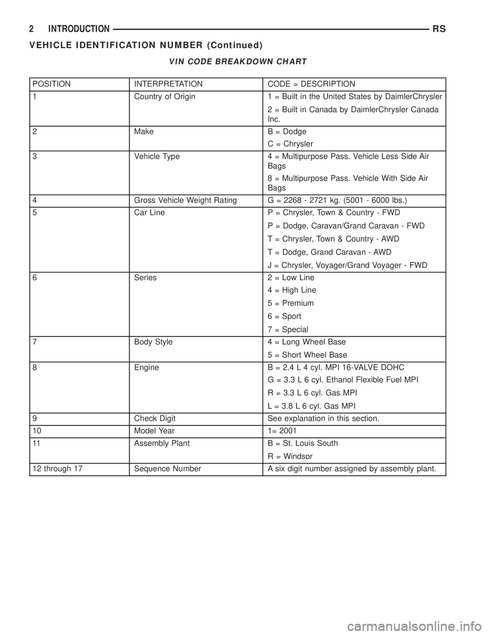
VIN CODE BREAKDOWN CHART
POSITION INTERPRETATION CODE = DESCRIPTION
1 Country of Origin 1 = Built in the United States by DaimlerChrysler
2 = Built in Canada by DaimlerChrysler Canada
Inc.
2 Make B = Dodge
C = Chrysler
3 Vehicle Type 4 = Multipurpose Pass. Vehicle Less Side Air
Bags
8 = Multipurpose Pass. Vehicle With Side Air
Bags
4 Gross Vehicle Weight Rating G = 2268 - 2721 kg. (5001 - 6000 lbs.)
5 Car Line P = Chrysler, Town & Country - FWD
P = Dodge, Caravan/Grand Caravan - FWD
T = Chrysler, Town & Country - AWD
T = Dodge, Grand Caravan - AWD
J = Chrysler, Voyager/Grand Voyager - FWD
6 Series 2 = Low Line
4 = High Line
5 = Premium
6 = Sport
7 = Special
7 Body Style 4 = Long Wheel Base
5 = Short Wheel Base
8 Engine B = 2.4 L 4 cyl. MPI 16-VALVE DOHC
G = 3.3 L 6 cyl. Ethanol Flexible Fuel MPI
R = 3.3 L 6 cyl. Gas MPI
L = 3.8 L 6 cyl. Gas MPI
9 Check Digit See explanation in this section.
10 Model Year 1= 2001
11 Assembly Plant B = St. Louis South
R = Windsor
12 through 17 Sequence Number A six digit number assigned by assembly plant.
2 INTRODUCTIONRS
VEHICLE IDENTIFICATION NUMBER (Continued)