2001 CHRYSLER VOYAGER oil reset
[x] Cancel search: oil resetPage 51 of 4284

On vehicles equipped with AutoStick, the display
includes an O/D OFF indicator that is illuminated
when the driver presses the Overdrive Off button
on the transaxle shifter.
3.11.1 INSTRUMENT CLUSTER SELF TEST
1. Depress and hold the Odometer Reset button.
2. Turn the ignition switch to the RUN/START
position.
3. Release the Odometer reset button.
The Instrument Cluster will illuminate all indi-
cators and step the gauges through several calibra-
tion points. Also, the odometer will display any
stored codes that may have set.
3.11.2 MESSAGE CENTER
The Message Center is located above the brow of
the Instrument Cluster. It houses the following
warning indicators: Check Engine/Service Engine
Soon, high beam, left and right turn signals, Secu-
rity Alarm Set, and low oil pressure. On base
models equipped with the three-speed transaxle,
these indicators appear in the face of the cluster.
The Security Alarm set indicator is a red circle.
Activation of Instrument Cluster indicators is
coordinated with indicators in the message center
and EVIC to avoid redundancy. A revised safety
standard now requires that the seat belt warning
lamp in the Instrument Cluster remain lit if the
driver seat belt is not buckled. A headlamp out ISO
indicator has been added to the Instrument Cluster
to alert the driver when a headlamp is not function-
ing.
3.12 INTERIOR LIGHTING
3.12.1 COURTESY LAMP CONTROL
The body controller has direct control over all of
the vehicle's courtesy lamps. The body computer
will illuminate the courtesy lamps under any of the
following conditions:
1. Any door ajar and courtesy lamp switch on the
headlamp switch is not in the dome off position.
2. The courtesy lamp switch on the headlamp
switch is in the dome on position.
3. A Remote Keyless Entry unlock message is re-
ceived.
4. Driver door unlocked with key (with VTSS only).
3.12.2 ILLUMINATED ENTRY
Illuminated entry will be initiated when the cus-
tomer enters the vehicle by unlocking the doors
with the key fob, or with the key if the vehicle is
equipped with vehicle theft alarm. Upon exiting thevehicle, if the lock button is pressed with a door
open, illuminated entry will cancel when the door
closes. If the doors are closed and the ignition
switch is turned on, the illuminated entry also
cancels. The illuminated entry feature will not
operate if the courtesy lamp switch is in the dome
off position.
3.12.3 INTERIOR LIGHTING BATTERY
SAVER
If any of the interior lamps are left on after the
ignition is turned off, the BCM will turn them off
after 8 minutes. To return to normal operation, the
courtesy lamps will operate after the dome lamp
switch or door ajar switch changes state. The glove
box and switched reading lamps require that the
ignition be turned to the on/acc position.
3.13 MEMORY SYSTEM
The memory system consists of power driver 's
seat, power mirrors and radio presets. The Memory
Seat/Mirror Module (MSMM) is located under the
driver 's seat. It receives input from the following:
driver 's manual 8-way seat switch, driver 's seat
position sensors, PCI bus circuits, and the power
mirror sensors. The module uses these inputs to
perform the following functions: position the driv-
er 's memory seat, both exterior mirrors (during
recalls), and send/receive the memory system infor-
mation over the PCI bus.
The Memory Set Switch is wired to the Body
Control Module (BCM). When a button (either #1 or
#2) is pressed on the set switch causes the to BCM
send a message to the MSMM which in turn sends
a motion status messages to the BCM. If the BCM
receives no motion from the MSMM it will send a
recall message to the MSMM and radio (once igni-
tion is in run or accessory). The MSMM will in turn
position the drivers seat, both mirrors along with
recalling the radio presets. If the drivers seat or
either exterior mirror is inoperative from its own
respective switches, use the service information
and schematic to diagnose the problem. This man-
ual addresses the memory problems only and it is
assumed there is not a basic component failure.
3.13.1 POWER SEAT
The memory power seat provides the driver with
2 position settings for the driver 's seat. Each power
seat motor is connected to the MSMM with two
motor drive circuits. Each circuit is switched be-
tween battery and ground. By being able to bi-
directionally drive the circuits, the MSMM controls
the movement of the motors based on input from
the power seat switch or from the position sensors
when performing a memory recall. Each motor
22
GENERAL INFORMATION
Page 743 of 4284
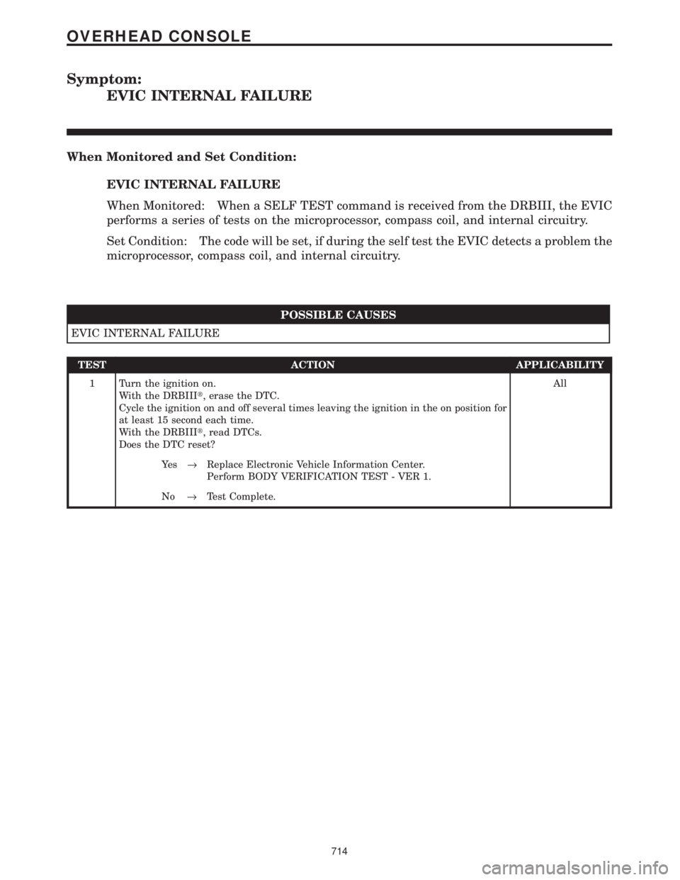
Symptom:
EVIC INTERNAL FAILURE
When Monitored and Set Condition:
EVIC INTERNAL FAILURE
When Monitored: When a SELF TEST command is received from the DRBIII, the EVIC
performs a series of tests on the microprocessor, compass coil, and internal circuitry.
Set Condition: The code will be set, if during the self test the EVIC detects a problem the
microprocessor, compass coil, and internal circuitry.
POSSIBLE CAUSES
EVIC INTERNAL FAILURE
TEST ACTION APPLICABILITY
1 Turn the ignition on.
With the DRBIIIt, erase the DTC.
Cycle the ignition on and off several times leaving the ignition in the on position for
at least 15 second each time.
With the DRBIIIt, read DTCs.
Does the DTC reset?All
Ye s®Replace Electronic Vehicle Information Center.
Perform BODY VERIFICATION TEST - VER 1.
No®Test Complete.
714
OVERHEAD CONSOLE
Page 1326 of 4284
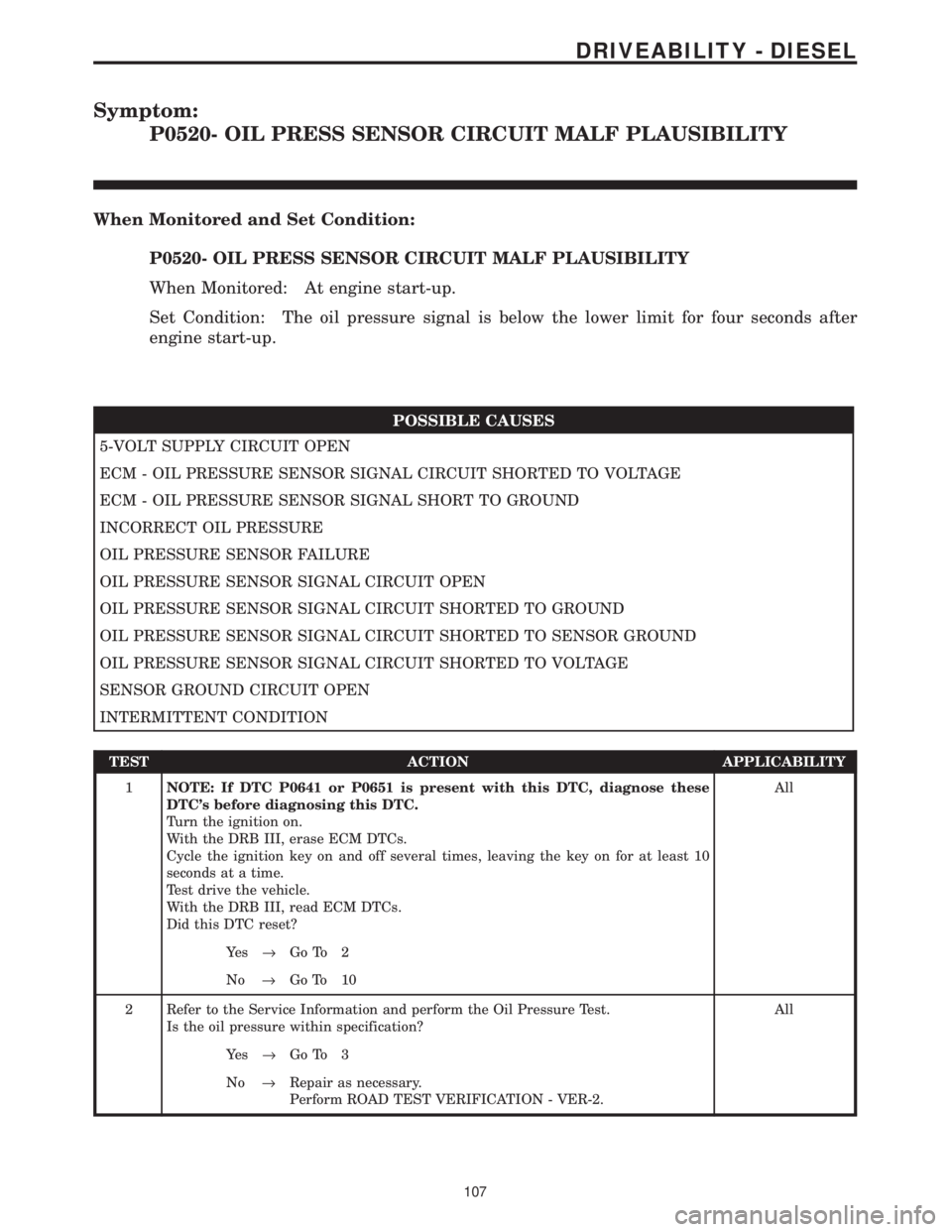
Symptom:
P0520- OIL PRESS SENSOR CIRCUIT MALF PLAUSIBILITY
When Monitored and Set Condition:
P0520- OIL PRESS SENSOR CIRCUIT MALF PLAUSIBILITY
When Monitored: At engine start-up.
Set Condition: The oil pressure signal is below the lower limit for four seconds after
engine start-up.
POSSIBLE CAUSES
5-VOLT SUPPLY CIRCUIT OPEN
ECM - OIL PRESSURE SENSOR SIGNAL CIRCUIT SHORTED TO VOLTAGE
ECM - OIL PRESSURE SENSOR SIGNAL SHORT TO GROUND
INCORRECT OIL PRESSURE
OIL PRESSURE SENSOR FAILURE
OIL PRESSURE SENSOR SIGNAL CIRCUIT OPEN
OIL PRESSURE SENSOR SIGNAL CIRCUIT SHORTED TO GROUND
OIL PRESSURE SENSOR SIGNAL CIRCUIT SHORTED TO SENSOR GROUND
OIL PRESSURE SENSOR SIGNAL CIRCUIT SHORTED TO VOLTAGE
SENSOR GROUND CIRCUIT OPEN
INTERMITTENT CONDITION
TEST ACTION APPLICABILITY
1NOTE: If DTC P0641 or P0651 is present with this DTC, diagnose these
DTC's before diagnosing this DTC.
Turn the ignition on.
With the DRB III, erase ECM DTCs.
Cycle the ignition key on and off several times, leaving the key on for at least 10
seconds at a time.
Test drive the vehicle.
With the DRB III, read ECM DTCs.
Did this DTC reset?All
Ye s®Go To 2
No®Go To 10
2 Refer to the Service Information and perform the Oil Pressure Test.
Is the oil pressure within specification?All
Ye s®Go To 3
No®Repair as necessary.
Perform ROAD TEST VERIFICATION - VER-2.
107
DRIVEABILITY - DIESEL
Page 1329 of 4284
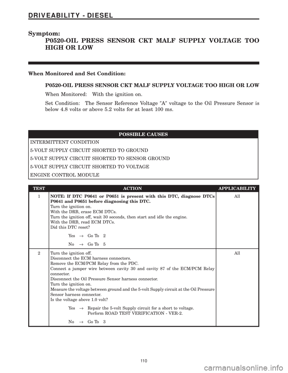
Symptom:
P0520-OIL PRESS SENSOR CKT MALF SUPPLY VOLTAGE TOO
HIGH OR LOW
When Monitored and Set Condition:
P0520-OIL PRESS SENSOR CKT MALF SUPPLY VOLTAGE TOO HIGH OR LOW
When Monitored: With the ignition on.
Set Condition: The Sensor Reference Voltage9A9voltage to the Oil Pressure Sensor is
below 4.8 volts or above 5.2 volts for at least 100 ms.
POSSIBLE CAUSES
INTERMITTENT CONDITION
5-VOLT SUPPLY CIRCUIT SHORTED TO GROUND
5-VOLT SUPPLY CIRCUIT SHORTED TO SENSOR GROUND
5-VOLT SUPPLY CIRCUIT SHORTED TO VOLTAGE
ENGINE CONTROL MODULE
TEST ACTION APPLICABILITY
1NOTE: If DTC P0641 or P0651 is present with this DTC, diagnose DTCs
P0641 and P0651 before diagnosing this DTC.
Turn the ignition on.
With the DRB, erase ECM DTCs.
Turn the ignition off, wait 30 seconds, then start and idle the engine.
With the DRB, read ECM DTCs.
Did this DTC reset?All
Ye s®Go To 2
No®Go To 5
2 Turn the ignition off.
Disconnect the ECM harness connectors.
Remove the ECM/PCM Relay from the PDC.
Connect a jumper wire between cavity 30 and cavity 87 of the ECM/PCM Relay
connector.
Disconnect the Oil Pressure Sensor harness connector.
Turn the ignition on.
Measure the voltage between ground and the 5-volt Supply circuit at the Oil Pressure
Sensor harness connector.
Is the voltage above 1.0 volt?All
Ye s®Repair the 5-volt Supply circuit for a short to voltage.
Perform ROAD TEST VERIFICATION - VER-2.
No®Go To 3
11 0
DRIVEABILITY - DIESEL
Page 1355 of 4284
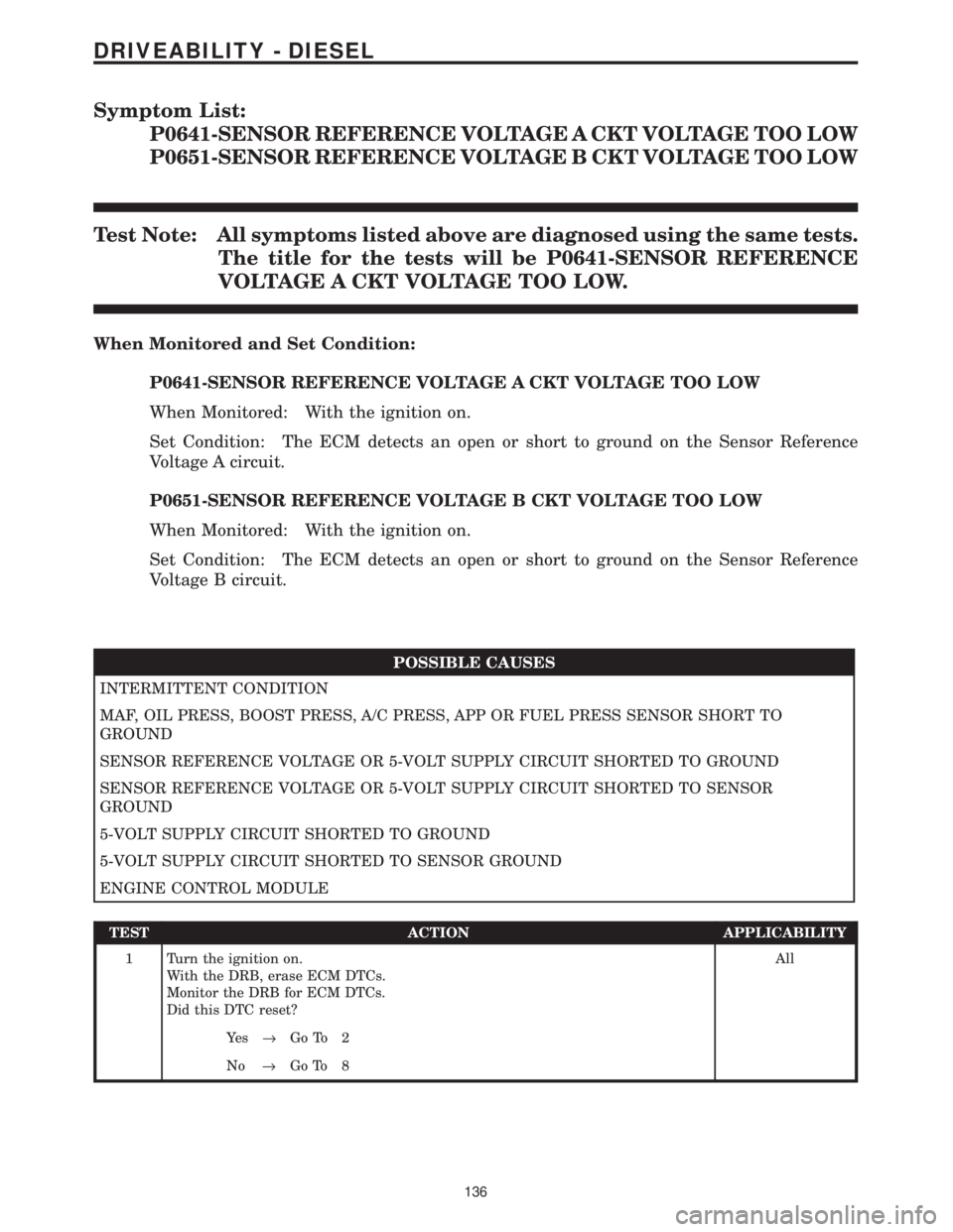
Symptom List:
P0641-SENSOR REFERENCE VOLTAGE A CKT VOLTAGE TOO LOW
P0651-SENSOR REFERENCE VOLTAGE B CKT VOLTAGE TOO LOW
Test Note: All symptoms listed above are diagnosed using the same tests.
The title for the tests will be P0641-SENSOR REFERENCE
VOLTAGE A CKT VOLTAGE TOO LOW.
When Monitored and Set Condition:
P0641-SENSOR REFERENCE VOLTAGE A CKT VOLTAGE TOO LOW
When Monitored: With the ignition on.
Set Condition: The ECM detects an open or short to ground on the Sensor Reference
Voltage A circuit.
P0651-SENSOR REFERENCE VOLTAGE B CKT VOLTAGE TOO LOW
When Monitored: With the ignition on.
Set Condition: The ECM detects an open or short to ground on the Sensor Reference
Voltage B circuit.
POSSIBLE CAUSES
INTERMITTENT CONDITION
MAF, OIL PRESS, BOOST PRESS, A/C PRESS, APP OR FUEL PRESS SENSOR SHORT TO
GROUND
SENSOR REFERENCE VOLTAGE OR 5-VOLT SUPPLY CIRCUIT SHORTED TO GROUND
SENSOR REFERENCE VOLTAGE OR 5-VOLT SUPPLY CIRCUIT SHORTED TO SENSOR
GROUND
5-VOLT SUPPLY CIRCUIT SHORTED TO GROUND
5-VOLT SUPPLY CIRCUIT SHORTED TO SENSOR GROUND
ENGINE CONTROL MODULE
TEST ACTION APPLICABILITY
1 Turn the ignition on.
With the DRB, erase ECM DTCs.
Monitor the DRB for ECM DTCs.
Did this DTC reset?All
Ye s®Go To 2
No®Go To 8
136
DRIVEABILITY - DIESEL
Page 1442 of 4284
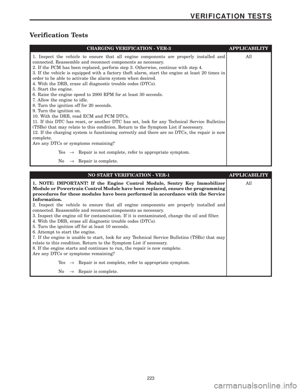
Verification Tests
CHARGING VERIFICATION - VER-3 APPLICABILITY
1. Inspect the vehicle to ensure that all engine components are properly installed and
connected. Reassemble and reconnect components as necessary.
2. If the PCM has been replaced, perform step 3. Otherwise, continue with step 4.
3. If the vehicle is equipped with a factory theft alarm, start the engine at least 20 times in
order to be able to activate the alarm system when desired.
4. With the DRB, erase all diagnostic trouble codes (DTCs).
5. Start the engine.
6. Raise the engine speed to 2000 RPM for at least 30 seconds.
7. Allow the engine to idle.
8. Turn the ignition off for 20 seconds.
9. Turn the ignition on.
10. With the DRB, read ECM and PCM DTCs.
11. If this DTC has reset, or another DTC has set, look for any Technical Service Bulletins
(TSBs) that may relate to this condition. Return to the Symptom List if necessary.
12. If the charging system is functioning correctly and there are no DTCs, the repair is now
complete.
Are any DTCs or symptoms remaining?All
Ye s®Repair is not complete, refer to appropriate symptom.
No®Repair is complete.
NO START VERIFICATION - VER-1 APPLICABILITY
1. NOTE: IMPORTANT! If the Engine Control Module, Sentry Key Immobilizer
Module or Powertrain Control Module have been replaced, ensure the programming
procedures for these modules have been performed in accordance with the Service
Information.
2. Inspect the vehicle to ensure that all engine components are properly installed and
connected. Reassemble and reconnect components as necessary.
3. Inspect the engine oil for contamination. If it is contaminated, change the oil and filter.
4. With the DRB, erase all diagnostic trouble codes (DTCs).
5. Turn the ignition off for at least 10 seconds.
6. Attempt to start the engine.
7. If the engine is unable to start, look for any Technical Service Bulletins (TSBs) that may
relate to this condition. Return to the Symptom List if necessary.
8. If the engine starts and continues to run, the repair is now complete.
Are any DTCs or symptoms remaining?All
Ye s®Repair is not complete, refer to appropriate symptom.
No®Repair is complete.
223
VERIFICATION TESTS
Page 1821 of 4284
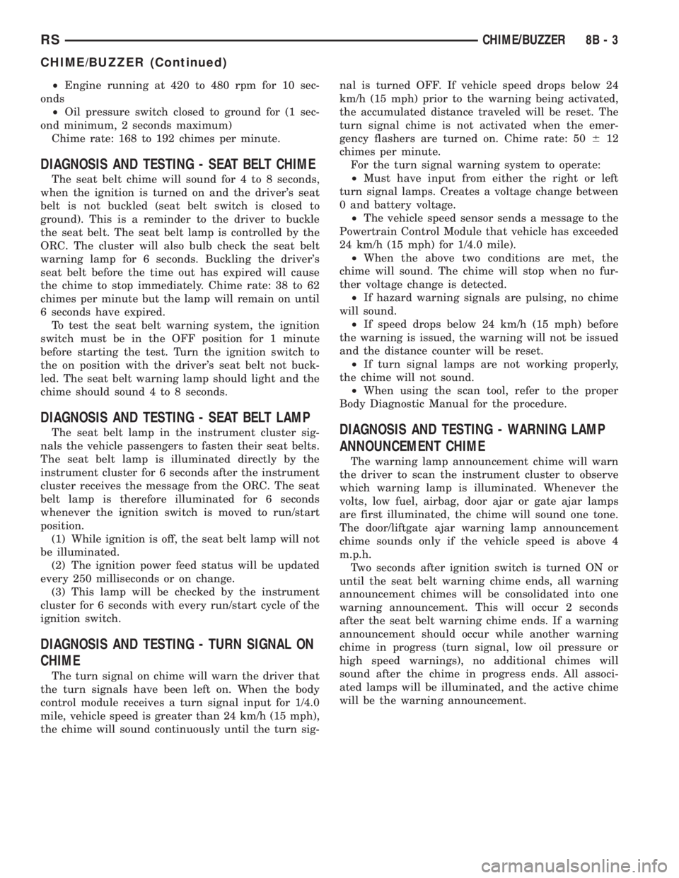
²Engine running at 420 to 480 rpm for 10 sec-
onds
²Oil pressure switch closed to ground for (1 sec-
ond minimum, 2 seconds maximum)
Chime rate: 168 to 192 chimes per minute.
DIAGNOSIS AND TESTING - SEAT BELT CHIME
The seat belt chime will sound for 4 to 8 seconds,
when the ignition is turned on and the driver's seat
belt is not buckled (seat belt switch is closed to
ground). This is a reminder to the driver to buckle
the seat belt. The seat belt lamp is controlled by the
ORC. The cluster will also bulb check the seat belt
warning lamp for 6 seconds. Buckling the driver's
seat belt before the time out has expired will cause
the chime to stop immediately. Chime rate: 38 to 62
chimes per minute but the lamp will remain on until
6 seconds have expired.
To test the seat belt warning system, the ignition
switch must be in the OFF position for 1 minute
before starting the test. Turn the ignition switch to
the on position with the driver's seat belt not buck-
led. The seat belt warning lamp should light and the
chime should sound 4 to 8 seconds.
DIAGNOSIS AND TESTING - SEAT BELT LAMP
The seat belt lamp in the instrument cluster sig-
nals the vehicle passengers to fasten their seat belts.
The seat belt lamp is illuminated directly by the
instrument cluster for 6 seconds after the instrument
cluster receives the message from the ORC. The seat
belt lamp is therefore illuminated for 6 seconds
whenever the ignition switch is moved to run/start
position.
(1) While ignition is off, the seat belt lamp will not
be illuminated.
(2) The ignition power feed status will be updated
every 250 milliseconds or on change.
(3) This lamp will be checked by the instrument
cluster for 6 seconds with every run/start cycle of the
ignition switch.
DIAGNOSIS AND TESTING - TURN SIGNAL ON
CHIME
The turn signal on chime will warn the driver that
the turn signals have been left on. When the body
control module receives a turn signal input for 1/4.0
mile, vehicle speed is greater than 24 km/h (15 mph),
the chime will sound continuously until the turn sig-nal is turned OFF. If vehicle speed drops below 24
km/h (15 mph) prior to the warning being activated,
the accumulated distance traveled will be reset. The
turn signal chime is not activated when the emer-
gency flashers are turned on. Chime rate: 50612
chimes per minute.
For the turn signal warning system to operate:
²Must have input from either the right or left
turn signal lamps. Creates a voltage change between
0 and battery voltage.
²The vehicle speed sensor sends a message to the
Powertrain Control Module that vehicle has exceeded
24 km/h (15 mph) for 1/4.0 mile).
²When the above two conditions are met, the
chime will sound. The chime will stop when no fur-
ther voltage change is detected.
²If hazard warning signals are pulsing, no chime
will sound.
²If speed drops below 24 km/h (15 mph) before
the warning is issued, the warning will not be issued
and the distance counter will be reset.
²If turn signal lamps are not working properly,
the chime will not sound.
²When using the scan tool, refer to the proper
Body Diagnostic Manual for the procedure.
DIAGNOSIS AND TESTING - WARNING LAMP
ANNOUNCEMENT CHIME
The warning lamp announcement chime will warn
the driver to scan the instrument cluster to observe
which warning lamp is illuminated. Whenever the
volts, low fuel, airbag, door ajar or gate ajar lamps
are first illuminated, the chime will sound one tone.
The door/liftgate ajar warning lamp announcement
chime sounds only if the vehicle speed is above 4
m.p.h.
Two seconds after ignition switch is turned ON or
until the seat belt warning chime ends, all warning
announcement chimes will be consolidated into one
warning announcement. This will occur 2 seconds
after the seat belt warning chime ends. If a warning
announcement should occur while another warning
chime in progress (turn signal, low oil pressure or
high speed warnings), no additional chimes will
sound after the chime in progress ends. All associ-
ated lamps will be illuminated, and the active chime
will be the warning announcement.
RSCHIME/BUZZER8B-3
CHIME/BUZZER (Continued)
Page 1843 of 4284
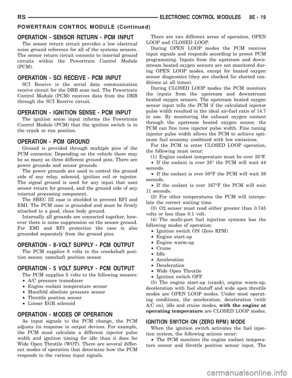
OPERATION - SENSOR RETURN - PCM INPUT
The sensor return circuit provides a low electrical
noise ground reference for all of the systems sensors.
The sensor return circuit connects to internal ground
circuits within the Powertrain Control Module
(PCM).
OPERATION - SCI RECEIVE - PCM INPUT
SCI Receive is the serial data communication
receive circuit for the DRB scan tool. The Powertrain
Control Module (PCM) receives data from the DRB
through the SCI Receive circuit.
OPERATION - IGNITION SENSE - PCM INPUT
The ignition sense input informs the Powertrain
Control Module (PCM) that the ignition switch is in
the crank or run position.
OPERATION - PCM GROUND
Ground is provided through multiple pins of the
PCM connector. Depending on the vehicle there may
be as many as three different ground pins. There are
power grounds and sensor grounds.
The power grounds are used to control the ground
side of any relay, solenoid, ignition coil or injector.
The signal ground is used for any input that uses
sensor return for ground, and the ground side of any
internal processing component.
The SBEC III case is shielded to prevent RFI and
EMI. The PCM case is grounded and must be firmly
attached to a good, clean body ground.
Internally all grounds are connected together, how-
ever there is noise suppression on the sensor ground.
For EMI and RFI protection the case is also
grounded separately from the ground pins.
OPERATION - 8-VOLT SUPPLY - PCM OUTPUT
The PCM supplies 8 volts to the crankshaft posi-
tion sensor, camshaft position sensor.
OPERATION - 5 VOLT SUPPLY - PCM OUTPUT
The PCM supplies 5 volts to the following sensors:
²A/C pressure transducer
²Engine coolant temperature sensor
²Manifold absolute pressure sensor
²Throttle position sensor
²Linear EGR solenoid
OPERATION - MODES OF OPERATION
As input signals to the PCM change, the PCM
adjusts its response to output devices. For example,
the PCM must calculate a different injector pulse
width and ignition timing for idle than it does for
Wide Open Throttle (WOT). There are several differ-
ent modes of operation that determine how the PCM
responds to the various input signals.There are two different areas of operation, OPEN
LOOP and CLOSED LOOP.
During OPEN LOOP modes the PCM receives
input signals and responds according to preset PCM
programming. Inputs from the upstream and down-
stream heated oxygen sensors are not monitored dur-
ing OPEN LOOP modes, except for heated oxygen
sensor diagnostics (they are checked for shorted con-
ditions at all times).
During CLOSED LOOP modes the PCM monitors
the inputs from the upstream and downstream
heated oxygen sensors. The upstream heated oxygen
sensor input tells the PCM if the calculated injector
pulse width resulted in the ideal air-fuel ratio of 14.7
to one. By monitoring the exhaust oxygen content
through the upstream heated oxygen sensor, the
PCM can fine tune injector pulse width. Fine tuning
injector pulse width allows the PCM to achieve opti-
mum fuel economy combined with low emissions.
For the PCM to enter CLOSED LOOP operation,
the following must occur:
(1) Engine coolant temperature must be over 35ÉF.
²If the coolant is over 35É the PCM will wait 44
seconds.
²If the coolant is over 50ÉF the PCM will wait 38
seconds.
²If the coolant is over 167ÉF the PCM will wait
11 seconds.
(2) For other temperatures the PCM will interpo-
late the correct waiting time.
(3) O2 sensor must read either greater than 0.745
volts or less than 0.1 volt.
(4) The multi-port fuel injection systems has the
following modes of operation:
²Ignition switch ON (Zero RPM)
²Engine start-up
²Engine warm-up
²Cruise
²Idle
²Acceleration
²Deceleration
²Wide Open Throttle
²Ignition switch OFF
(5) The engine start-up (crank), engine warm-up,
deceleration with fuel shutoff and wide open throttle
modes are OPEN LOOP modes. Under most operat-
ing conditions, the acceleration, deceleration (with
A/C on), idle and cruise modes,with the engine at
operating temperatureare CLOSED LOOP modes.IGNITION SWITCH ON (ZERO RPM) MODE
When the ignition switch activates the fuel injec-
tion system, the following actions occur:
²The PCM monitors the engine coolant tempera-
ture sensor and throttle position sensor input. The
RSELECTRONIC CONTROL MODULES8E-19
POWERTRAIN CONTROL MODULE (Continued)