2001 CHRYSLER VOYAGER lights
[x] Cancel search: lightsPage 38 of 4284
This feature dims the interior lighting (courtesy
lamps) gradually if the BCM does not receive any
new inputs that would cause the interior lamps to
remain on.
²PWM Instrument Panel Dimming
²Door Lock Inhibit
This feature disables the door lock functions if the
key is in the ignition and either front door is ajar.
Pressing the RKE lock/unlock button under these
conditions, result in normal lock/unlock activation.
²Power Sliding Door Switch Inputs
The BCM has 4 switch inputs for the power
sliding door feature: Located in the overhead con-
sole are the Left and Right side sliding door
switches to activate either or both sliding doors
under the proper conditions. Also are B-Pillar
switches located on the Left and Right B-pillar
posts.
²Power Liftgate Switch Input
The BCM has 1 Liftgate switch input located in
the overhead console
²Power Lockout Switch Input
The BCM has 1 Lockout switch that when en-
abled will disable the B-Pillar sliding door switches
from activating either sliding door when depressed.
When replacing a body control module there are 2
modules available, a Base and a Midline. The
Midline controller is used on vehicles that have
Power Door Locks. If a vehicle is equipped with the
Vehicle Theft Security System, the midline control-
ler becomes a premium when the theft feature is
enabled.
NOTE: DO NOT SWAP THE BODY CONTROL
MODULE BETWEEN VEHICLES OR BODY
CONTROL MODULES OFF THE SHELF.
Engineering does not recommend that service,
dealers or the plant swap Body Control Modules
(BCM) between vehicles or off the shelf. The BCM
has internal diagnostic capability that assists in
diagnosing the system. When an ªOpenº or a
ªShortº circuit exists, the diagnostic tool can be
used to read the BCM codes. The codes are very
descriptive in identifying the appropriate feature
that has faulted.
3.4 CHIME WARNING SYSTEM
The BCM monitors the door/liftgate ajar
switches, multifunction switches, headlight switch,
ignition switch, PCI bus, and the diagnostic tool to
perform various chime operations. The BCM uses a
low-side driver to control the chime located in the
cluster.
The chime system provides the Driver with warn-
ing chimes for:
²Seat belt
²Exterior lights on
²Key-in Ignition
²Key-in Accessory
²Engine temperature critical
²Low washer fluid
²Turn signals on
²Dome light on
²Low oil pressure
²Any warning lamp announcement
²High-speed warning Gulf Coast Countries (GCC)
only
The output sound intensity of the chime is ap-
proximately 72 decibels.
3.4.1 CHIME PRIORITY
The following list indicates the priority of the
chime when more than one chime is active at the
same time:
²Seat belt warning
²High-speed warning Gulf Coast Countries (GCC)
only
²Turn signal on
²Chime request
²Warning lamp announcement
The cluster is responsible to set priority on all
warning lamp announcement chimes.
3.4.2 CHIME ON CONDITIONS
The following is a list of the chime warnings and
when they will sound.
Driver 's Seat
belt Unbuckled:Sounds for approximately 662
seconds when the igntion is turned
on and driver 's seat belt is not
buckled, as a reminder to the
driver to buckle the seat belt.
Exterior Lights
On:Ignition is in the lock position,
the driver door is ajar, and the
headlight switch is left in any
position, other than auto or off.
The chime will sound as a warn-
ing to the driver until one of the
above conditions is removed or
until the battery protection time
of 3 minutes has expired.
Key-In Ignition: Ignition is in the lock position,
driver door is ajar and the key is
in the ignition. The chime will
sound until one of the above con-
ditions is removed or until the
battery protection time of 15 min-
utes has expired.
9
GENERAL INFORMATION
Page 39 of 4284
Turn Signal On: When the BCM detects a turn
signal input continuously for
1.0mile/0.6km and the vehicle
speed is greater than 15 mph/
24kph, the chime will sound until
the specific turn signal is can-
celled.
Dome Lights On: Ignition is in the lock position,
driver door ajar, and the dome
light switch is left in the on
position. The chime will sound
until one of the above conditions
is removed or until the battery
protection time of 15 minutes has
expired.
Low Oil Pres-
sure:The chime will sound when the
engine is operating and the oil
pressure drops below 4psi/27.5kPa.
Engine
Temperature
Critical:The chime will sound when the
engine is operating and the cool-
ant temperature exceeds 252ÉF/
122Cor 234É/112C(diesel).The
chime is continuous at 257ÉF/
125C and will chime for 4 min-
utes and stop if the temperature
drops below 255ÉF/123C.
Low Washer
FluidThe chime will sound when the
washer fluid drops below a spe-
cific level.
Warning Lamp
Announcement:A chime will sound to alert the
driver to scan the instrument
panel to see which warning lamp
is illuminated. The door/liftgate
ajar warning lamp will appear
without a chime if the vehicle is
running and a door or the liftgate
is opened. A chime will sound if
the door or liftgate is still open
and the vehicle speed is greater
than 4mph/6kph.
High-speed
warning Gulf
Coast Countries
(GCC) onlyThe chime will sound, acting as a
warning to the driver that the
vehicle speed has exceed
75mph62/120kph63.3.4.3 WARNING LAMP ANNOUNCEMENT
Low Fuel Lamp: The cluster will request a single
chime after the indicator is illu-
minated.
Volt Lamp: The cluster will request a single
chime after the indicator is illu-
minated.
Oil Pressure
Lamp:The cluster will request a single
chime after illuminating the in-
dicator above 450rpm vehicle op-
eration.
Headlight Out
Lamp:The cluster will request a single
chime after the indicator is illu-
minated.
Liftgate Ajar
Lamp:The BCM determines when to
chime for liftgate ajar.
Fasten Seat Belt
Lamp:The BCM will request five chimes
from the MIC when the ignition
is turned to the unlock/run/start
positions if the driver seat belt is
not buckled.
Check Engine
Lamp:The cluster will request a single
chime after the indicator is illu-
minated.
Low Washer
Fluid Lamp:The cluster will request a single
chime after the indicator is illu-
minated.
Engine Tempera-
ture Lamp:The cluster will request a single
chime when the indicator is first
illuminated at 252ÉF/122C.
3.4.4 OTHER CHIME ON CONDITIONS
Bulb Check: The chime will sound three times
during bulb check.
Programming of
an Additional
Key Fob:A double cluster chime will sound,
which signals that the program
mode has been initiated.
Programming for
Rolling Door
Locks:When the programming has been
completed, a single tone from the
chime system, will occur.
10
GENERAL INFORMATION
Page 412 of 4284
Symptom:
*BUS +/- SIGNALS OPEN OR NO RESPONSE FROM INSTRUMENT
CLUSTER
POSSIBLE CAUSES
ATTEMPT TO COMMUNICATE WITH THE BCM
OPEN GROUND CIRCUIT
OPEN FUSED B+ CIRCUIT
OPEN PCI BUS CIRCUIT
INSTRUMENT CLUSTER WAKE UP SENSE CKT OPEN
INSTRUMENT CLUSTER WAKE UP SENSE CKT INTERNALLY OPEN
INSTRUMENT CLUSTER WAKE UP SENSE CKT SHORTED TO VOLTAGE
INSTRUMENT CLUSTER WAKE UP SENSE CKT INTERNALLY SHORTED TO VOLTAGE
INSTRUMENT CLUSTER
BODY CONTROL MODULE
TEST ACTION APPLICABILITY
1 Turn the ignition on.
With the DRB, enter Body then Body Computer.
Was the DRB able to I/D or communicate with the BCM?All
Ye s®Go To 2
No®Refer to the symptom list for problems related to no communica-
tion with the BCM.
Perform BODY VERIFICATION TEST - VER 1.
2 Turn the ignition off.
Turn all lights off.
Disconnect the Instrument Cluster harness connector.
Measure the resistance between ground and both ground circuits.
Is the resistance below 10.0 ohms?All
Ye s®Go To 3
No®Repair the ground circuit for an open.
Perform BODY VERIFICATION TEST - VER 1.
3 Turn the ignition off.
Disconnect the Instrument Cluster harness connector.
Using a 12-volt test light connected to ground, probe the Fused B+ circuit.
Is the test light illuminated?All
Ye s®Go To 4
No®Repair the Fused B+ circuit for an open.
Perform BODY VERIFICATION TEST - VER 1.
383
COMMUNICATION
Page 449 of 4284

Symptom:
*NO RESPONSE FROM TRANSMISSION CONTROL MODULE
POSSIBLE CAUSES
NO RESPONSE FROM TRANSMISSION CONTROL MODULE
FCM OUTPUT (RUN/ST) CIRCUIT OPEN
IGNITION SWITCH OUTPUT (START) CIRCUIT OPEN
FUSED B(+) CIRCUIT OPEN
GROUND CIRCUIT(S) OPEN
OPEN PCI BUS CIRCUIT
TRANSMISSION CONTROL MODULE
TEST ACTION APPLICABILITY
1 Turn the ignition on.
Note: As soon as one or more module communicates with the DRB, answer
the question.
With the DRB, attempt to communicate with the Airbag Control Module (ACM).
With the DRB, attempt to communicate with the Body Control Module (BCM).
Was the DRB able to I/D or establish communications with either of the modules?All
Ye s®Go To 2
No®Refer to the Body Communication category and perform the
symptom PCI Bus Communication Failure.
Perform 41TE TRANSMISSION VERIFICATION TEST - VER 1.
2 Turn the ignition off.
Disconnect the TCM harness connector.
Turn the ignition on.
Using a 12-volt test light connected to ground, probe the FCM Output (Run/St)
circuit.
Note: The light must illuminate brightly, if it does not light, or lights dimly,
the circuit must be repaired. If there is any doubt, compare the brightness
when testing the circuit, to the brightness when connected directly to the
battery positive post.
Is the test light illuminated?All
Ye s®Go To 3
No®Repair the FCM Output (Run/St) circuit for an open. Refer to the
wiring diagrams location in the Service Information.
Perform 41TE TRANSMISSION VERIFICATION TEST - VER 1.
420
COMMUNICATION
Page 450 of 4284

TEST ACTION APPLICABILITY
3 Turn the ignition off.
Disconnect the TCM harness connector.
Remove the starter relay from the IPM.
Using a 12-volt test light connected to ground, probe the Ignition Switch Output
(Start) circuit.
Note: The light must illuminate brightly, if it does not light, or lights dimly,
the circuit must be repaired. If there is any doubt, compare the brightness
when testing the circuit, to the brightness when connected directly to the
battery positive post.
Observe the test light while momentarily turning the ignition switch to the Start
position.
Is the test light illuminated?All
Ye s®Go To 4
No®Repair the Ignition Switch Output (Start) circuit for an open.
Refer to the wiring diagrams located in the Service Information.
Perform 41TE TRANSMISSION VERIFICATION TEST - VER 1.
Note: Reinstall the original Starter Relay.
4 Turn the ignition off.
Disconnect the TCM harness connector.
Using a 12-volt test light connected to ground, probe the Fused B(+) circuit.
Note: The light must illuminate brightly, if it does not light, or lights dimly,
the circuit must be repaired. If there is any doubt, compare the brightness
when testing the circuit, to the brightness when connected directly to the
battery positive post.
Is the test light illuminated?All
Ye s®Go To 5
No®Check IPM fuse #15 for an open. If OK, repair the Fused B(+)
circuit for an open. Refer to the wiring diagrams located in the
Service Information.
Perform 41TE TRANSMISSION VERIFICATION TEST - VER 1.
5 Turn the ignition off.
Disconnect the TCM harness connector.
Using a 12-volt test light connected to 12-volts, probe each ground circuit in the TCM
connector.
NOTE: The light must illuminate brightly, if it does not light, or lights dimly,
the circuit must be repaired. If there is any doubt, compare the brightness
when testing the circuit, to the brightness when connected directly to the
battery negative post.
Is the light illuminated at all ground circuits?All
Ye s®Go To 6
No®Repair the Ground circuit(s) for an open. Check the main ground
connection to engine block and/or chassis. Refer to the wiring
diagrams located in the Service Information.
Perform 41TE TRANSMISSION VERIFICATION TEST - VER 1.
421
COMMUNICATION
*NO RESPONSE FROM TRANSMISSION CONTROL MODULE ÐContinued
Page 1495 of 4284
LUBRICANTS AND GREASES
Lubricating grease is rated for quality and usage
by the NLGI. All approved products have the NLGI
symbol (Fig. 7) on the label. At the bottom NLGI
symbol is the usage and quality identification letters.
Wheel bearing lubricant is identified by the letter
ªGº. Chassis lubricant is identified by the latter ªLº.
The letter following the usage letter indicates the
quality of the lubricant. The following symbols indi-
cate the highest quality.
OPERATION
The cooling system is designed around the coolant.
The coolant must accept heat from engine metal, in
the cylinder head area near the exhaust valves and
engine block. Then coolant carries the heat to the
radiator where the tube/fin radiator can transfer the
heat to the air.
WARNING: ANTIFREEZE IS AN ETHYLENE GLYCOL
BASE COOLANT AND IS HARMFUL IF SWAL-
LOWED OR INHALED. IF SWALLOWED, DRINK
TWO GLASSES OF WATER AND INDUCE VOMIT-
ING. IF INHALED, MOVE TO FRESH AIR AREA.
SEEK MEDICAL ATTENTION IMMEDIATELY. DO NOT
STORE IN OPEN OR UNMARKED CONTAINERS.
WASH SKIN AND CLOTHING THOROUGHLY AFTER
COMING IN CONTACT WITH ETHYLENE GLYCOL.
KEEP OUT OF REACH OF CHILDREN. DISPOSE OF
GLYCOL BASE COOLANT PROPERLY, CONTACT
YOUR DEALER OR GOVERNMENT AGENCY FOR
LOCATION OF COLLECTION CENTER IN YOUR
AREA. DO NOT OPEN A COOLING SYSTEM WHEN
THE ENGINE IS AT OPERATING TEMPERATURE OR
HOT UNDER PRESSURE, PERSONAL INJURY CAN
RESULT. AVOID RADIATOR COOLING FAN WHEN
ENGINE COMPARTMENT RELATED SERVICE IS
PERFORMED, PERSONAL INJURY CAN RESULT.
FLUID FILL/CHECK
LOCATIONS
DESCRIPTION
The fluid check/fill points and lubrication locations
are located in each applicable Sections.
MAINTENANCE SCHEDULES
DESCRIPTION
There are two maintenance schedules that show
proper service for your vehicle.
First is Schedule ±A. It lists all the scheduled
maintenance to be performed under ªnormalº operat-
ing conditions.
Second is Schedule ±B. It is a schedule for vehi-
cles that are operated under the following conditions:
²Frequent short trip driving less than 10 miles
(16.2 km)
²Frequent driving in dusty conditions
²Frequent off-road or desert operation
²Frequent trailer towing
²Day and night temperatures are below freezing
²Frequent long periods of engine idling
²Frequent stop and go driving
²More than 50% of your driving is at sustained
high speeds during hot weather, above 90ÉF (32ÉC)*
²Taxi, police or delivery service
²If equipped for and operation with E-85
(ethanol) fuel.
DESCRIPTION
At Each Stop For Fuel
²Check engine oil level and add as required.
²Check windshield washer solvent and add as
required.
Once A Month
²Check tire pressure and look for unusual wear
or damage.
²Check fluid levels of coolant reservoir, brake
master cylinder, power steering and transmission.
Add fluid as required.
²Check all lights and all other electrical items for
correct operation.
At Each Oil Change
²Change oil filter
²Inspect the exhaust system.
²Inspect brake hoses.
²Inspect the CV joints and front suspension com-
ponent boots and seals.
²Rotate the tires at each oil change interval
shown on Schedule ± A (7,500 miles - 12 000 km) or
Fig. 7 NLGI Symbol
1 - WHEEL BEARINGS
2 - CHASSIS LUBRICATION
3 - CHASSIS AND WHEEL BEARINGS
RSLUBRICATION & MAINTENANCE0-7
FLUID TYPES (Continued)
Page 1511 of 4284
FLUID FILL/CHECK
LOCATIONS
DESCRIPTION
The fluid check/fill points and lubrication locations
are located in each applicable service manual section.
MAINTENANCE SCHEDULES
MAINTENANCE SCHEDULES - DIESEL ENGINE
There are two maintenance schedules that show
proper service for the vehicle.
First is ScheduleªAº. It lists all the scheduled
maintenance to be performed under ªnormalº operat-
ing conditions.
Second is ScheduleªBº. It is a schedule for vehi-
cles that are operated under the conditions listed at
the beginning of the schedule.
Use the schedule that best describes the driving
conditions.
Where time and mileage are listed, follow the
interval that occurs first.
At Each Stop for Fuel
²Check the engine oil level, add as required.
²Check the windshield washer solvent and add if
required.
Once a Month
²Check the tire pressure and look for unusual
wear or damage.
²Inspect the battery and clean and tighten termi-
nals as required.
²Check the fluid levels of coolant reservoir, brake
master cylinder, power steering and transaxle and
add as needed.
²Check all lights and all other electrical items for
correct operation.
²Check the rubber seals on each side of the radi-
ator for proper fit.
At Each Oil Change
²Replace the engine oil filter at each oil change.
²Inspect exhaust system.
²Inspect brake hoses
²Inspect the CV joints and front suspension com-
ponents
²Rotate the tires at each oil change interval
shown on schedule ªAº 20 000 km or every other
interval shown on schedule ªBº 20 000 km.
²Check the coolant level, hoses, and clamps.
²Inspect brake linings, hoses and calipers.
²Inspect engine accessory drive belts.
²Inspect for presence of water in fuel filter/water
separator, drain if necessary.
SCHEDULE ªAº
20 000 km (12 000 miles)
²Change engine oil. (1)
²Replace engine oil filter.
²Inspect air filter element. Replace as necessary.
40 000 km (24 000 Miles)
²Change engine oil. (1)
²Replace engine oil filter.
²Replace air filter element.
²Replace fuel filter/water separator element. (2)
²Check alignment.
60 000 km (37 000 Miles)
²Change engine oil. (1)
²Replace engine oil filter.
²Inspect air filter element. Replace as necessary.
80 000 km (49 000 Miles)
²Change engine oil. (1)
²Replace engine oil filter.
²Replace air filter element.
²Replace fuel filter/water separator element. (2)
²Check alignment.
100 000 km (62 000 Miles)
²Change engine oil. (1)
²Replace engine oil filter.
²Inspect air filter element. Replace as necessary.
120 000 km (75 000 Miles)
²Change engine oil. (1)
²Replace engine oil filter.
²Replace air filter element.
²Replace fuel filter/water separator element. (2)
²Check alignment.
140 000 km (86 000 miles)
²Change engine oil. (1)
²Replace engine oil filter.
²Inspect air filter element. Replace as necessary.
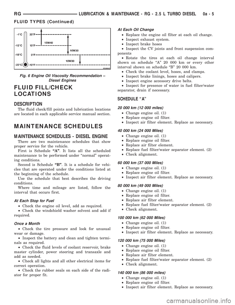
Fig. 6 Engine Oil Viscosity Recommendation ±
Diesel Engines
RGLUBRICATION & MAINTENANCE - RG - 2.5 L TURBO DIESEL0a-5
FLUID TYPES (Continued)
Page 1820 of 4284
FASTEN SEAT BELT LAMP OR TONE CONTINUES
FOR MORE THAN 10 SECONDS AFTER SEAT
BELTS ARE FASTENED AND DRIVER'S DOOR IS
CLOSED.
Refer to the proper Body Diagnostic Procedures
manual.
NO TONE WHEN PARK OR HEADLAMPS ARE ON
AND DRIVER'S DOOR IS OPEN.
Make sure ignition is in lock position with the key
removed.
(1) Check the BCM DTC's and BCM sensors to
verify the door is open. Repair as necessary.
(2) Actuate Chime (BCM actuates).
(3) Inspect BCM connectors and wires for proper
connection.
(4) Measure with a voltmeter the voltage (12v) on
BCM connector (PX2) pin 34 with harness connected.
DIAGNOSIS AND TESTING - DOME LAMP ON
CHIME
The dome lamp on chime will warn the driver that
the dome lamps have been left on.
When the ignition is OFF:
²Driver's door OPEN (door ajar switch is closed to
ground) and
²Dome lamps are ON (dome lamp switch is closed
to ground),
The chime will sound continuously until driver's
door is closed, dome lamps tuned OFF or until the
battery protection time out of 15 minutes has
expired. Chime rate: 168 to 192 chimes per minute.
DIAGNOSIS AND TESTING - ENGINE
TEMPERATURE CRITICAL CHIME
The engine temperature critical chime will warn
the driver that the vehicle's engine is overheating.
While monitoring the coolant temperature, the Pow-
ertrain Control Module (PCM) will send on the PCI
data bus as engine temperature every 1.376 seconds
to the cluster. The MIC calculates engine tempera-
ture and determines if a warning should occur. This
feature is functional only with the Ignition Switch in
the Run/Start position.
When the engine temperature reaches 122ÉC
(252ÉF) the MIC requests a chime from the BCM and
the engine temperature lamp comes ON. The MIC
turns OFF the lamp when the engine temperature
reaches 117ÉC (242ÉF). The MIC will chime continu-
ously (request from the BCM). The chime will turn
OFF after four minutes or when the temperature
reaches 117ÉC (242ÉF), which ever occurs first.
DIAGNOSIS AND TESTING - EXTERIOR LAMPS
ON CHIME
The exterior lamp on chime will warn the driver
that the exterior lights have been left on.
With the ignition switch OFF/key out of ignition:
²Driver's door is open (door ajar switch is closed
to ground)
²Parking lamps or headlamps ON (parking lamp
switch is closed to ground)
The chime will sound until lights are turned OFF,
driver's door closed or until the battery protection
time out of 3 minutes has expired.
Chime rate: 168 to 192 chimes per minute.
To test the exterior lamps left on function:
²Turn ignition off
²Remove ignition key
²Turn exterior lamps on with driver's door open.
Chime should sound until lamps are turned off or
driver's door is closed.
DIAGNOSIS AND TESTING - KEY-IN IGNITION
CHIME
The key-in ignition chime will act as a warning to
the driver that the ignition key has been left in the
ignition switch.
With the ignition switch is in OFF position ONLY:
²Driver's door is open/ajar (door ajar switch is
closed to ground)
²Key is in the ignition switch (ignition is in the
LOCK position)
The chime will sound until one of the above condi-
tions is removed or until battery protection time out
(15 min.) has expired. Chime rate: 168 to 192 chimes
per minute.
To test the key-in ignition function, insert key into
the ignition and open driver's door. Do not turn igni-
tion ON. Chime should sound until key is removed
from ignition or driver's door is closed.
For diagnosis and testing of the Key-In Accessory
chime, use the same testing procedure as above but
with the key in the accessory position.
DIAGNOSIS AND TESTING - LOW OIL
PRESSURE CHIME
The low oil pressure chime will warn the driver
that the engine oil pressure is low. The oil pressure
switch will close to ground during a low oil pressure
condition. The oil pressure lamp will illuminate in
the message center. The PCM will monitor the oil
pressure switch and signal a low oil pressure condi-
tion. A continuous four minute warning chime will
sound and the oil pressure lamp will come ON when
the following conditions are met:
²Ignition on and engine not cranking
8B - 2 CHIME/BUZZERRS
CHIME/BUZZER (Continued)