2001 CHRYSLER VOYAGER key fob
[x] Cancel search: key fobPage 39 of 4284
Turn Signal On: When the BCM detects a turn
signal input continuously for
1.0mile/0.6km and the vehicle
speed is greater than 15 mph/
24kph, the chime will sound until
the specific turn signal is can-
celled.
Dome Lights On: Ignition is in the lock position,
driver door ajar, and the dome
light switch is left in the on
position. The chime will sound
until one of the above conditions
is removed or until the battery
protection time of 15 minutes has
expired.
Low Oil Pres-
sure:The chime will sound when the
engine is operating and the oil
pressure drops below 4psi/27.5kPa.
Engine
Temperature
Critical:The chime will sound when the
engine is operating and the cool-
ant temperature exceeds 252ÉF/
122Cor 234É/112C(diesel).The
chime is continuous at 257ÉF/
125C and will chime for 4 min-
utes and stop if the temperature
drops below 255ÉF/123C.
Low Washer
FluidThe chime will sound when the
washer fluid drops below a spe-
cific level.
Warning Lamp
Announcement:A chime will sound to alert the
driver to scan the instrument
panel to see which warning lamp
is illuminated. The door/liftgate
ajar warning lamp will appear
without a chime if the vehicle is
running and a door or the liftgate
is opened. A chime will sound if
the door or liftgate is still open
and the vehicle speed is greater
than 4mph/6kph.
High-speed
warning Gulf
Coast Countries
(GCC) onlyThe chime will sound, acting as a
warning to the driver that the
vehicle speed has exceed
75mph62/120kph63.3.4.3 WARNING LAMP ANNOUNCEMENT
Low Fuel Lamp: The cluster will request a single
chime after the indicator is illu-
minated.
Volt Lamp: The cluster will request a single
chime after the indicator is illu-
minated.
Oil Pressure
Lamp:The cluster will request a single
chime after illuminating the in-
dicator above 450rpm vehicle op-
eration.
Headlight Out
Lamp:The cluster will request a single
chime after the indicator is illu-
minated.
Liftgate Ajar
Lamp:The BCM determines when to
chime for liftgate ajar.
Fasten Seat Belt
Lamp:The BCM will request five chimes
from the MIC when the ignition
is turned to the unlock/run/start
positions if the driver seat belt is
not buckled.
Check Engine
Lamp:The cluster will request a single
chime after the indicator is illu-
minated.
Low Washer
Fluid Lamp:The cluster will request a single
chime after the indicator is illu-
minated.
Engine Tempera-
ture Lamp:The cluster will request a single
chime when the indicator is first
illuminated at 252ÉF/122C.
3.4.4 OTHER CHIME ON CONDITIONS
Bulb Check: The chime will sound three times
during bulb check.
Programming of
an Additional
Key Fob:A double cluster chime will sound,
which signals that the program
mode has been initiated.
Programming for
Rolling Door
Locks:When the programming has been
completed, a single tone from the
chime system, will occur.
10
GENERAL INFORMATION
Page 51 of 4284

On vehicles equipped with AutoStick, the display
includes an O/D OFF indicator that is illuminated
when the driver presses the Overdrive Off button
on the transaxle shifter.
3.11.1 INSTRUMENT CLUSTER SELF TEST
1. Depress and hold the Odometer Reset button.
2. Turn the ignition switch to the RUN/START
position.
3. Release the Odometer reset button.
The Instrument Cluster will illuminate all indi-
cators and step the gauges through several calibra-
tion points. Also, the odometer will display any
stored codes that may have set.
3.11.2 MESSAGE CENTER
The Message Center is located above the brow of
the Instrument Cluster. It houses the following
warning indicators: Check Engine/Service Engine
Soon, high beam, left and right turn signals, Secu-
rity Alarm Set, and low oil pressure. On base
models equipped with the three-speed transaxle,
these indicators appear in the face of the cluster.
The Security Alarm set indicator is a red circle.
Activation of Instrument Cluster indicators is
coordinated with indicators in the message center
and EVIC to avoid redundancy. A revised safety
standard now requires that the seat belt warning
lamp in the Instrument Cluster remain lit if the
driver seat belt is not buckled. A headlamp out ISO
indicator has been added to the Instrument Cluster
to alert the driver when a headlamp is not function-
ing.
3.12 INTERIOR LIGHTING
3.12.1 COURTESY LAMP CONTROL
The body controller has direct control over all of
the vehicle's courtesy lamps. The body computer
will illuminate the courtesy lamps under any of the
following conditions:
1. Any door ajar and courtesy lamp switch on the
headlamp switch is not in the dome off position.
2. The courtesy lamp switch on the headlamp
switch is in the dome on position.
3. A Remote Keyless Entry unlock message is re-
ceived.
4. Driver door unlocked with key (with VTSS only).
3.12.2 ILLUMINATED ENTRY
Illuminated entry will be initiated when the cus-
tomer enters the vehicle by unlocking the doors
with the key fob, or with the key if the vehicle is
equipped with vehicle theft alarm. Upon exiting thevehicle, if the lock button is pressed with a door
open, illuminated entry will cancel when the door
closes. If the doors are closed and the ignition
switch is turned on, the illuminated entry also
cancels. The illuminated entry feature will not
operate if the courtesy lamp switch is in the dome
off position.
3.12.3 INTERIOR LIGHTING BATTERY
SAVER
If any of the interior lamps are left on after the
ignition is turned off, the BCM will turn them off
after 8 minutes. To return to normal operation, the
courtesy lamps will operate after the dome lamp
switch or door ajar switch changes state. The glove
box and switched reading lamps require that the
ignition be turned to the on/acc position.
3.13 MEMORY SYSTEM
The memory system consists of power driver 's
seat, power mirrors and radio presets. The Memory
Seat/Mirror Module (MSMM) is located under the
driver 's seat. It receives input from the following:
driver 's manual 8-way seat switch, driver 's seat
position sensors, PCI bus circuits, and the power
mirror sensors. The module uses these inputs to
perform the following functions: position the driv-
er 's memory seat, both exterior mirrors (during
recalls), and send/receive the memory system infor-
mation over the PCI bus.
The Memory Set Switch is wired to the Body
Control Module (BCM). When a button (either #1 or
#2) is pressed on the set switch causes the to BCM
send a message to the MSMM which in turn sends
a motion status messages to the BCM. If the BCM
receives no motion from the MSMM it will send a
recall message to the MSMM and radio (once igni-
tion is in run or accessory). The MSMM will in turn
position the drivers seat, both mirrors along with
recalling the radio presets. If the drivers seat or
either exterior mirror is inoperative from its own
respective switches, use the service information
and schematic to diagnose the problem. This man-
ual addresses the memory problems only and it is
assumed there is not a basic component failure.
3.13.1 POWER SEAT
The memory power seat provides the driver with
2 position settings for the driver 's seat. Each power
seat motor is connected to the MSMM with two
motor drive circuits. Each circuit is switched be-
tween battery and ground. By being able to bi-
directionally drive the circuits, the MSMM controls
the movement of the motors based on input from
the power seat switch or from the position sensors
when performing a memory recall. Each motor
22
GENERAL INFORMATION
Page 53 of 4284

seconds instead of 5, the CMTC will set the
variance to 8 and enter the fast calibration
mode.
3. The VAR light will come on and the last variance
setting will be displayed.
4. Press the STEP button to set the zone number.
5. Press the US/M button and resume normal op-
eration.
NOTE: Do not attach any magnetic device
such as a magnetic CB antenna to the
vehicle. This can cause the compass to give
false readings.
3.15 POWER DOOR LOCK SYSTEM
When the BCM receives input for a lock request
from a door lock switch, RKE or cylinder lock switch
(only with VTSS), it will turn the lock driver on for
a specified time of 375 msec. If the request is there
beyond 375 msec, the BCM considers the door lock
signal stuck. Once a door lock or unlock signal is
stuck for longer than 10 seconds, the BCM will set
a trouble code and the signal input is ignored until
the stuck condition disappears. The door lock
switches provide a variable amount of resistance
thereby dropping the voltage of the multiplexed
(MUX) circuit and the BCM will respond to that
command.
3.15.1 SLIDING DOOR MEMORY LOCK
When the BCM receives an input for a lock
request and a sliding door is open, the BCM will
turn on the lock driver as described above, and will
turn it on again when all sliding doors are closed.
NOTE: If the BCM receives an unlock input before
a sliding door is closed, this will cancel the memory
lock.
3.15.2 DOOR LOCK INHIBIT
When the key is in the ignition and in any
position and either front door is open, the door lock
switches LOCK functions are disabled. The UN-
LOCK functions are still functional. This protects
against locking the vehicle with the keys still in the
ignition. The RKE key fob will still lock the doors as
usual. This allows the driver to lock the vehicle with
the engine running for warm up.
3.15.3 AUTOMATIC DOOR LOCKS
This feature can be enabled or disabled by using
either the DRBIIItor the customer programming
method. When enabled all the doors will lock when
the vehicle reaches a speed of 18 MPH (29 KMH)
and all the doors are closed. If a door is opened and
the vehicle slows to below 18 MPH (29 KMH), thedoor locks will operate again once all doors are
closed and the speed is above 15 MPH (24 KMH).
3.15.4 REMOTE KEYLESS ENTRY (RKE)
The body control module interfaces with the RKE
module via a one-way serial bus interface. The RKE
module is not on the PCI bus. The RKE module
sends a 0-5 volt pulse width signal to the BCM
depending on which button on the transmitter was
pressed. The BCM controls the door lock/unlock
functions and the arming/disarming of the Vehicle
Theft Security System (if equipped) and the activa-
tion of illuminated entry. The BCM will also send
the appropriate messages to the Power Sliding
Doors and Power Liftgate modules. The Intelligent
Power Module (IPM) activates the park lamps,
headlamps, and horn for horn chirp when sent the
appropriate message from the BCM as received
from the RKE transmitter. When a one-button
press is made for unlock, both driver side doors will
unlock and the front and rear turn signal will flash.
When a second press is initiated (within 5 seconds
of the first) both passenger doors will unlock and all
four turn signals will flash.
The RKE module is capable of retaining up to 4
individual access codes (4 transmitters). If the
PRNDL is in any position except park, the BCM will
ground the interface thereby disabling the RKE.
The 2 button transmitter will have 2-CR2016
batteries in series. The 5 button transmitter will
have 1-CR2016 battery. The minimum battery life
should be approximately 4.7 years based on 20
transmissions a day at 84ÉF (25ÉC). Using the
DRBIIItand selecting RKE FOB Test can test the
transmitter.
The RKE module can be programmed via the
DRBIIItor the customer programming method.
The BCM will only allow programming mode to be
entered when the ignition is in the on position, the
PRNDL is in park position, and the VTSS (if
equipped) is in the disarmed mode.
3.16 POWER FOLDING MIRRORS
The power folding mirrors are powered to two
positions: folded and unfolded. The driver may
choose fold or unfold with a switch that is located on
the right side of the steering column. The folding
mirror switch grounds a sense wire that comes from
the Body Control Module when it is placed in the
fold position. The mirrors will move to the position
designated by the switch whether the ignition
switch is the On or Off position and both front doors
are closed. When the Power Folding Mirror switch
is left in the fold position during a vehicle exit the
mirrors will automatically unfold then refold after
both front doors are closed. This is to prevent mirror
contact with either front door when opened. When
24
GENERAL INFORMATION
Page 1982 of 4284
POWER LIFTGATE SYSTEM
DESCRIPTION
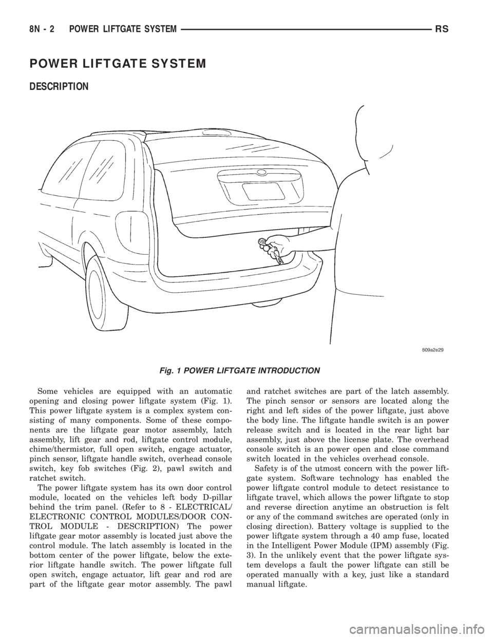
Some vehicles are equipped with an automatic
opening and closing power liftgate system (Fig. 1).
This power liftgate system is a complex system con-
sisting of many components. Some of these compo-
nents are the liftgate gear motor assembly, latch
assembly, lift gear and rod, liftgate control module,
chime/thermistor, full open switch, engage actuator,
pinch sensor, liftgate handle switch, overhead console
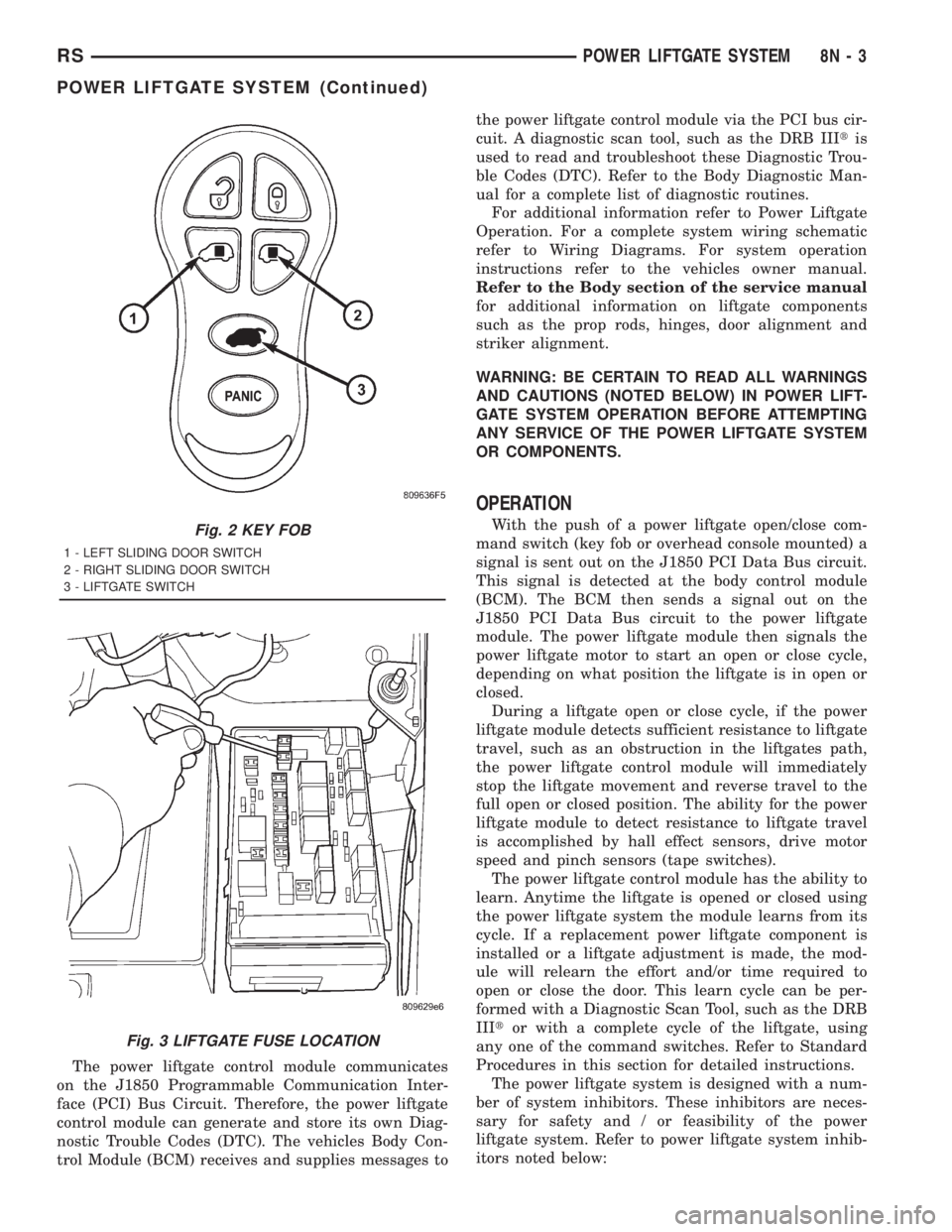
switch, key fob switches (Fig. 2), pawl switch and
ratchet switch.
The power liftgate system has its own door control
module, located on the vehicles left body D-pillar
behind the trim panel. (Refer to 8 - ELECTRICAL/
ELECTRONIC CONTROL MODULES/DOOR CON-
TROL MODULE - DESCRIPTION) The power
liftgate gear motor assembly is located just above the
control module. The latch assembly is located in the
bottom center of the power liftgate, below the exte-
rior liftgate handle switch. The power liftgate full
open switch, engage actuator, lift gear and rod are
part of the liftgate gear motor assembly. The pawland ratchet switches are part of the latch assembly.
The pinch sensor or sensors are located along the
right and left sides of the power liftgate, just above
the body line. The liftgate handle switch is an power
release switch and is located in the rear light bar
assembly, just above the license plate. The overhead
console switch is an power open and close command
switch located in the vehicles overhead console.
Safety is of the utmost concern with the power lift-
gate system. Software technology has enabled the
power liftgate control module to detect resistance to
liftgate travel, which allows the power liftgate to stop
and reverse direction anytime an obstruction is felt
or any of the command switches are operated (only in
closing direction). Battery voltage is supplied to the
power liftgate system through a 40 amp fuse, located
in the Intelligent Power Module (IPM) assembly (Fig.
3). In the unlikely event that the power liftgate sys-
tem develops a fault the power liftgate can still be
operated manually with a key, just like a standard
manual liftgate.
Fig. 1 POWER LIFTGATE INTRODUCTION
8N - 2 POWER LIFTGATE SYSTEMRS
Page 1983 of 4284
The power liftgate control module communicates
on the J1850 Programmable Communication Inter-
face (PCI) Bus Circuit. Therefore, the power liftgate
control module can generate and store its own Diag-
nostic Trouble Codes (DTC). The vehicles Body Con-
trol Module (BCM) receives and supplies messages tothe power liftgate control module via the PCI bus cir-
cuit. A diagnostic scan tool, such as the DRB IIItis
used to read and troubleshoot these Diagnostic Trou-
ble Codes (DTC). Refer to the Body Diagnostic Man-
ual for a complete list of diagnostic routines.
For additional information refer to Power Liftgate
Operation. For a complete system wiring schematic
refer to Wiring Diagrams. For system operation
instructions refer to the vehicles owner manual.
Refer to the Body section of the service manual
for additional information on liftgate components
such as the prop rods, hinges, door alignment and
striker alignment.
WARNING: BE CERTAIN TO READ ALL WARNINGS
AND CAUTIONS (NOTED BELOW) IN POWER LIFT-
GATE SYSTEM OPERATION BEFORE ATTEMPTING
ANY SERVICE OF THE POWER LIFTGATE SYSTEM
OR COMPONENTS.
OPERATION
With the push of a power liftgate open/close com-
mand switch (key fob or overhead console mounted) a
signal is sent out on the J1850 PCI Data Bus circuit.
This signal is detected at the body control module
(BCM). The BCM then sends a signal out on the
J1850 PCI Data Bus circuit to the power liftgate
module. The power liftgate module then signals the
power liftgate motor to start an open or close cycle,
depending on what position the liftgate is in open or
closed.
During a liftgate open or close cycle, if the power
liftgate module detects sufficient resistance to liftgate
travel, such as an obstruction in the liftgates path,
the power liftgate control module will immediately
stop the liftgate movement and reverse travel to the
full open or closed position. The ability for the power
liftgate module to detect resistance to liftgate travel
is accomplished by hall effect sensors, drive motor
speed and pinch sensors (tape switches).
The power liftgate control module has the ability to
learn. Anytime the liftgate is opened or closed using
the power liftgate system the module learns from its
cycle. If a replacement power liftgate component is
installed or a liftgate adjustment is made, the mod-
ule will relearn the effort and/or time required to
open or close the door. This learn cycle can be per-
formed with a Diagnostic Scan Tool, such as the DRB
IIItor with a complete cycle of the liftgate, using
any one of the command switches. Refer to Standard
Procedures in this section for detailed instructions.
The power liftgate system is designed with a num-
ber of system inhibitors. These inhibitors are neces-
sary for safety and / or feasibility of the power
liftgate system. Refer to power liftgate system inhib-
itors noted below:Fig. 2 KEY FOB
1 - LEFT SLIDING DOOR SWITCH
2 - RIGHT SLIDING DOOR SWITCH
3 - LIFTGATE SWITCH
Fig. 3 LIFTGATE FUSE LOCATION
RSPOWER LIFTGATE SYSTEM8N-3
POWER LIFTGATE SYSTEM (Continued)
Page 1987 of 4284
CONDITION POSSIBLE CAUSES CORRECTION
Key fob, Outside Handle or
overhead console switches
do not power operate
liftgateBlown Fuse Check fuse and replace
Battery voltage low Charge or replace battery in key fob or
vehicle
Failure of latch assembly Check for foreign matter preventing the
operation of latch assembly
Check wire connection
Pawl and/or ratchet switch inoperative
Replace latch if necessary
Wiring problems (system or vehicle) Troubleshoot using electrical schematics.
Refer to wiring diagrams
Failure of Body Control Module
(BCM)Check electrical connections
Refer to the Body electrical troubleshooting
guide for additional checks
Replace BCM if necessary
Failure of key fob Reprogram key fob
Replace key fob if necessary
Failure of Power Liftgate Module Disconnect then reconnect battery to reset
module, function liftgate, if no function
exists check for loose wire connections,
see Body Diagnostic Manual for detailed
procedures
Failure of liftgate motor assembly Check for foreign matter preventing the
operation of gear motor assembly
Check wire connections
Motor clutch does not engage, replace
assembly
Full open switch inoperative, replace
switch, if necessary
Troubleshoot using Body Diagnostic
Manual Replace motor, if necessary
Liftgate does not stay open Failure of liftgate prop rods Replace prop rods, if necessary
Check for broken attachments
High inside/outside opening
effortFailure of liftgate prop rods Replace prop rods, if necessary
Check for broken attachments
Gear motor did not disengage Troubleshoot using Body Diagnostic
Manual Replace components, if necessary
Binding or sticking of components Establish location of binding and replace
necessary components
RSPOWER LIFTGATE SYSTEM8N-7
POWER LIFTGATE SYSTEM (Continued)
Page 1997 of 4284
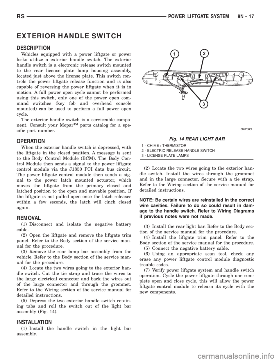
EXTERIOR HANDLE SWITCH
DESCRIPTION
Vehicles equipped with a power liftgate or power
locks utilize a exterior handle switch. The exterior
handle switch is a electronic release switch mounted
to the rear license plate lamp housing assembly,
located just above the license plate. This switch con-
trols the power liftgate release function and is also
capable of reversing the power liftgate when it is in
motion. A full power open cycle cannot be performed
using this switch, only one of the power open com-
mand switches (key fob and overhead console
mounted) can be used to perform a full power open
cycle.
The exterior handle switch is a serviceable compo-
nent. Consult your MoparŸ parts catalog for a spe-
cific part number.
OPERATION
When the exterior handle switch is depressed, with
the liftgate in the closed position. A message is sent
to the Body Control Module (BCM). The Body Con-
trol Module then sends a signal to the power liftgate
control module via the J1850 PCI data bus circuit.
The power liftgate control module then sends a sig-
nal to the power latch mounted actuator, which
moves the liftgate from the primary closed and
latched position to the open and movable position. If
the liftgate is not pulled open once the latch releases
within a few seconds, the latch will cinch closed
again.
REMOVAL
(1) Disconnect and isolate the negative battery
cable.
(2) Open the liftgate and remove the liftgate trim
panel. Refer to the Body section of the service man-
ual for the procedure.
(3) Remove the rear lamp bar assembly from the
vehicle. Refer to the Body section of the service man-
ual for the procedure.
(4) Locate the two wires going to the exterior han-
dle switch. Cut the tie strap and trace the wires to
the large electrical connector and back the wires out
of the large connector and through the grommet.
Refer to the Wiring section of the service manual for
detailed instructions.
(5) Depress the two exterior handle switch retain-
ing tabs and roll the switch out of the light bar
assembly (Fig. 14).
INSTALLATION
(1) Install the handle switch in the light bar
assembly.(2) Locate the two wires going to the exterior han-
dle switch. Install the wires through the grommet
and in the large connector. Secure with a tie strap.
Refer to the Wiring section of the service manual for
detailed instructions.
NOTE: Be certain wires are reinstalled in the correct
wire cavities. Failure to do so could result in dam-
age to the handle switch. Refer to Wiring Diagrams
if previous notes were not made.
(3) Install the rear light bar. Refer to the Body sec-
tion of the service manual for the procedure.
(4) Install the liftgate trim panel. Refer to the
Body section of the service manual for the procedure.
(5) Connect the negative battery cable.
(6) Using an appropriate scan tool, check any
erase any power liftgate control module diagnostic
trouble codes.
(7) Verify power liftgate system and handle switch
operation. Cycle the power liftgate through one com-
plete open and close cycle, this will allow the power
liftgate control module to relearn its cycle with the
new components.
Fig. 14 REAR LIGHT BAR
1 - CHIME / THERMISTOR
2 - ELECTRIC RELEASE HANDLE SWITCH
3 - LICENSE PLATE LAMPS
RSPOWER LIFTGATE SYSTEM8N-17
Page 1999 of 4284
POWER SLIDING DOOR SYSTEM
TABLE OF CONTENTS
page page
POWER SLIDING DOOR SYSTEM
DESCRIPTION...........................19
OPERATION.............................21
DIAGNOSIS AND TESTING.................22
DIAGNOSIS AND TESTING - POWER
SLIDING DOOR SYSTEM.................22
STANDARD PROCEDURE..................28
WELLNUT REPLACEMENT...............28
POWER DOOR LEARN CYCLE............28
SLIDING DOOR ADJUSTMENT............28
LATCH
DESCRIPTION...........................29
OPERATION.............................29
REMOVAL..............................29
INSTALLATION...........................30
SLIDING DOOR MOTOR
DESCRIPTION...........................30
OPERATION.............................30
REMOVAL..............................31
INSTALLATION...........................31
FULL OPEN SWITCH
DESCRIPTION...........................31
OPERATION.............................31
LEFT B-PILLAR SWITCH
DESCRIPTION...........................32
OPERATION.............................32
REMOVAL..............................32INSTALLATION...........................32
RIGHT B-PILLAR SWITCH
DESCRIPTION...........................32
OPERATION.............................32
REMOVAL..............................32
INSTALLATION...........................32
LOWER DRIVE UNIT
DESCRIPTION...........................33
OPERATION.............................33
REMOVAL..............................33
INSTALLATION...........................34
LOWER DRIVE UNIT TRACK & RACK
DESCRIPTION...........................34
OPERATION.............................34
REMOVAL..............................34
INSTALLATION...........................35
WIRING HARNESS
DESCRIPTION...........................35
OPERATION.............................35
REMOVAL..............................35
INSTALLATION...........................36
FLEX DRIVE
DESCRIPTION...........................36
OPERATION.............................36
REMOVAL..............................37
INSTALLATION...........................38
POWER SLIDING DOOR
SYSTEM
DESCRIPTION
Some vehicles are equipped with a power opening
and closing sliding door system (Fig. 1). Depending
on how the vehicle is ordered it may be equipped
with only a right side power door or right and left
side power doors. This power sliding door system is a
complex system consisting of many components.
Some of these components are the door motor, latch
assembly, sliding door control module, lower drive
unit, flex drive assembly, wire harness and track,
lower drive unit track and rack assembly, full open
switch, B-pillar switch, overhead console switch, key
fob switches (Fig. 2), pawl switch, ratchet switch and
child lockout and handle switches.
Each power side door has its own door control mod-
ule, located in the center of the door behind the door
trim panel. (Refer to 8 - ELECTRICAL/ELEC-TRONIC CONTROL MODULES/DOOR CONTROL
MODULE - DESCRIPTION) The power side door
motor is located in the front portion of the door, on
the inner door panel sheet metal. The latch assembly
is located in the rear of the power side door, near the
body line. The lower drive unit is attached to the
lower door hinge. The flex drive assembly connects
the door motor to the lower drive unit. The wire har-
ness and track and the lower drive unit track are vis-
ible with the door open in the lower door sill area.
The power side door full open switch is located under
the lower drive unit and is part of the hold open
latch assembly. The pawl, ratchet, handle and child
lockout switches are all located on the power side
door latch assembly. The B-pillar switch, as it will be
referred to, is an open and close command switch
located on the vehicles interior body side B-pillar
trim. The overhead console switch, is an open and
close command switch located in the vehicle's over-
head console. More detailed information can be found
on these components later in this section.
RSPOWER SLIDING DOOR SYSTEM8N-19