2001 CHRYSLER VOYAGER fuse box
[x] Cancel search: fuse boxPage 1071 of 4284
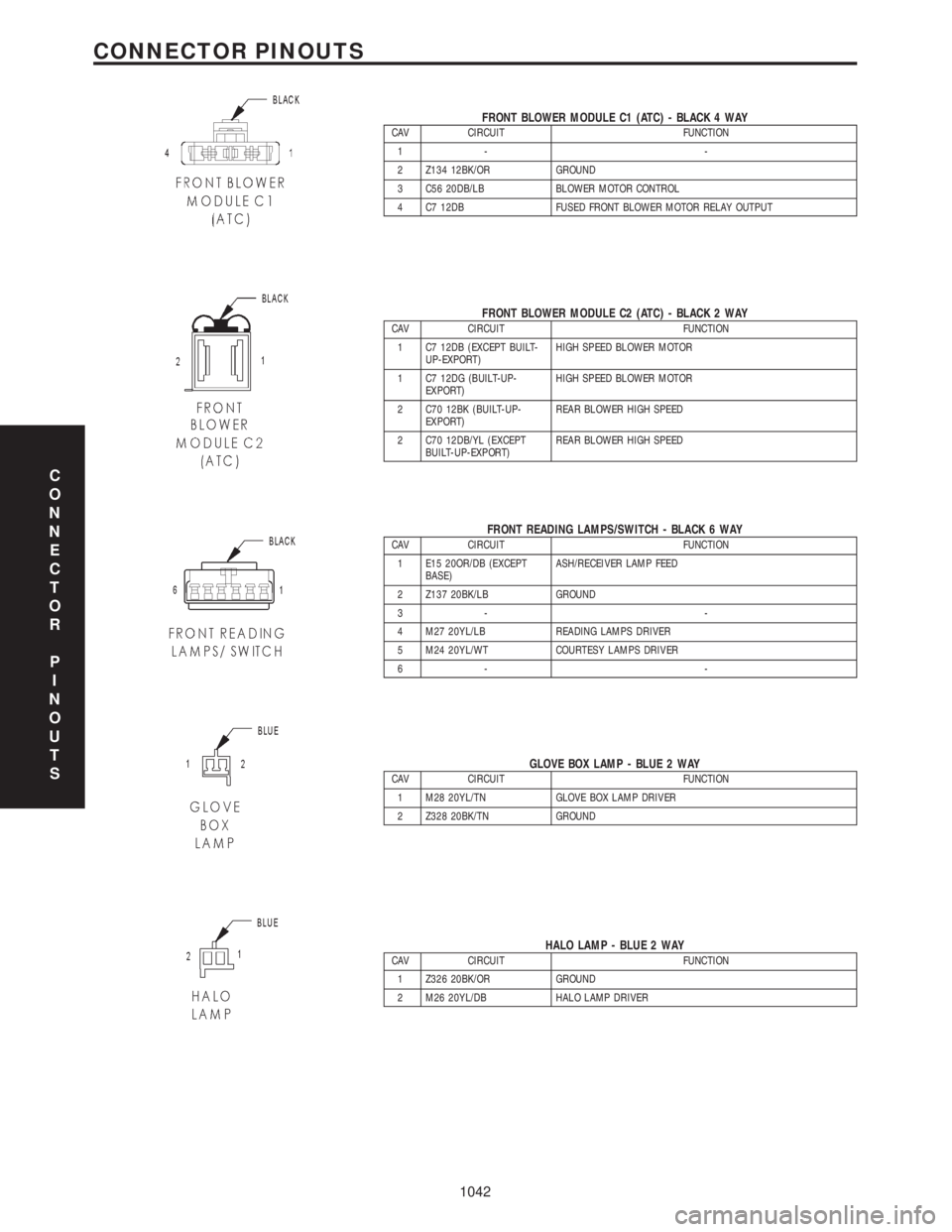
FRONT BLOWER MODULE C1 (ATC) - BLACK 4 WAYCAV CIRCUIT FUNCTION
1- -
2 Z134 12BK/OR GROUND
3 C56 20DB/LB BLOWER MOTOR CONTROL
4 C7 12DB FUSED FRONT BLOWER MOTOR RELAY OUTPUT
FRONT BLOWER MODULE C2 (ATC) - BLACK 2 WAYCAV CIRCUIT FUNCTION
1 C7 12DB (EXCEPT BUILT-
UP-EXPORT)HIGH SPEED BLOWER MOTOR
1 C7 12DG (BUILT-UP-
EXPORT)HIGH SPEED BLOWER MOTOR
2 C70 12BK (BUILT-UP-
EXPORT)REAR BLOWER HIGH SPEED
2 C70 12DB/YL (EXCEPT
BUILT-UP-EXPORT)REAR BLOWER HIGH SPEED
FRONT READING LAMPS/SWITCH - BLACK 6 WAYCAV CIRCUIT FUNCTION
1 E15 20OR/DB (EXCEPT
BASE)ASH/RECEIVER LAMP FEED
2 Z137 20BK/LB GROUND
3- -
4 M27 20YL/LB READING LAMPS DRIVER
5 M24 20YL/WT COURTESY LAMPS DRIVER
6- -
GLOVE BOX LAMP - BLUE 2 WAYCAV CIRCUIT FUNCTION
1 M28 20YL/TN GLOVE BOX LAMP DRIVER
2 Z328 20BK/TN GROUND
HALO LAMP - BLUE 2 WAYCAV CIRCUIT FUNCTION
1 Z326 20BK/OR GROUND
2 M26 20YL/DB HALO LAMP DRIVER
C
O
N
N
E
C
T
O
R
P
I
N
O
U
T
S
1042
CONNECTOR PINOUTS
Page 1163 of 4284
4.3 WARNINGS
4.3.1 VEHICLE DAMAGE WARNINGS
Before disconnecting any control module, make
sure the ignition is ``off ''. Failure to do so could
damage the module.
When testing voltage or continuity at any control
module, use the terminal side (not the wire end) of
the connector. Do not probe a wire through the
insulation, this will damage it and eventually cause
it to fail because of corrosion.
Be careful when performing electrical tests so as
to prevent accidental shorting of terminals. Such
mistakes can damage fuses or components. Also, a
second code could be set, making diagnosis of the
original problem more difficult.
4.3.2 ROAD TESTING A COMPLAINT
VEHICLE
Some complaints will require a test drive as part
of the repair verification procedure. The purpose of
the test drive is to try to duplicate the diagnostic
code or symptom condition.
WARNING: BEFORE ROAD TESTING A
VEHICLE, BE SURE THAT ALL
COMPONENTS ARE REASSEMBLED.
DURING THE TEST DRIVE, DO NOT TRY TO
READ THE DRB SCREEN WHILE IN MOTION.
DO NOT HANG THE DRBIIITFROM THE
REAR VIEW MIRROR OR OPERATE IT
YOURSELF. HAVE AN ASSISTANT
AVAILABLE TO OPERATE THE DRBIIIT.
4.4 DIAGNOSIS
1. Your diagnostic test procedure must begin with a
thorough visual inspection of the ABS system for
damaged components or disconnected connec-
tors. The brake lamps must be operational, and
if they are not, repair them prior to continuing.
2. Connect the DRBIIItto the data link connector,
which is located under the dash to the left of the
steering column. If the DRBIIItdoes not power
up, check the power and ground supplies to the
connector.
3. Turn the ignition on. Select ªAntilock Brakesº. If
the DRBIIItdisplays ªNo Responseº condition
you must diagnose that first.
4. Read and record all ABS diagnostic trouble
codes. If the ªCAB Power Feed Circuitº diagnos-
tic trouble code is present, it must be repaired
prior to addressing any other DTC's. If any
additional DTC's are present, proceed to theappropriate test by locating the matching test in
the Table of Contents and begin to diagnose the
symptom.
5. If there are no diagnostic trouble codes present,
identify the customer complaint. Select ªInputs/
Outputsº and read the brake switch input as you
press and release the brake pedal. If the display
does not match the state of the pedal, perform
the proper test by locating the matching test in
the Table of Contents and begin to diagnose the
symptom. If a problem exists with the yellow
ªABSº warning indicator or the red ªBrakeº
indicator exists, refer to the proper tests by
locating the matching test in the Table of Con-
tents and begin to diagnose the symptom. Read
the traction control switch input as you press
and release the switch. If the display does not
match the state of the indicator perform the
proper test by locating the matching test in the
Table of Contents and begin to diagnose the
symptom.
6. If no other problems are found, it will be neces-
sary to road test the vehicle. Perform several
antilock stops from above 50 Km/h (30 mph) and
then repeat step 4. If any diagnostic trouble
codes are present, proceed to the appropriate test.
7. The following conditions should be considered
ªNORMALº operation, and no repairs should be
attempted to correct them.
± Brake pedal feedback during an ABS stop
(clicking, vibrating).
± Clicking, groaning or buzzing at 25 Km/h (15
mph) or 40 Km/h (24 mph) (drive off self test).
± Groaning noise during an ABS stop.
± Slight brake pedal drop and pop noise when
ignition is initially turned on.
± Brake pedal ratcheting down at the end of an
ABS stop.
8. If the complaint is ABS ªcyclingº at the end of a
stop at low speeds, it may be caused by a
marginal wheel speed sensor signal. The sensor
air gap, tone wheel condition, and/or brakes
hanging up are possible causes of this condition.
9. After a road test in which no problems were
found, refer to any Technical Service Bulletins
that may apply.
5.0 REQUIRED TOOLS AND
EQUIPMENT
DRBIIIt(diagnostic read-out box)
jumper wires
ohmmeter
voltmeter
test light
6
GENERAL INFORMATION
Page 1227 of 4284
4.3 WARNINGS AND CAUTIONS
4.3.1 ROAD TEST WARNINGS
Some complaints will require a test drive as part
of the repair verification procedure. The purpose of
the test drive is to try to duplicate the diagnostic
code or symptom condition.
CAUTION: BEFORE ROAD TESTING A
VEHICLE, BE SURE THAT ALL
COMPONENTS ARE REASSEMBLED. DUR-
ING THE TEST DRIVE, DO NOT HANG THE
DRBIIITFROM THE REAR VIEW MIRROR. DO
NOT ATTEMPT TO READ THE DRBIIITWHILE
DRIVING. HAVE AN ASSISTANT AVAILABLE
TO OPERATE THE DRBIIIT.
4.3.2 VEHICLE DAMAGE CAUTIONS
Before disconnecting any control module, make
sure the ignition is off. Failure to do so could
damage the module. When testing voltage or circuit
integrity at any control module, use the terminal
side (not the wire end) of the harness connector. Do
not probe through the insulation; this will damage
it and eventually cause it to fail because of corro-
sion.
Be careful when performing electrical test so as to
prevent accidental shorting of terminals. Such a
mistake can damage fuses or components. Also, a
second code could be set, making diagnosis of the
original problem more difficult.
5.0 REQUIRED TOOLS AND
EQUIPMENT
DRBIIIt(diagnostic read-out box) scan tool
vacuum gauge
ammeter
ohmmeter
jumper wires and probes
oscilloscope
6.0 GLOSSARY OF TERMS
A/Cair conditioning
APPaccelerator pedal position (sensor)
backfire,
popbackfuel ignites in either the intake or
the exhaust system
BCMbody control module
BPboost pressure (sensor)CKPcrankshaft position (sensor)
CMPcamshaft position (sensor)
cuts out,
missesa steady pulsation or the inability of
the engine to maintain a consistent
rpm
DLCdata link connector
detona-
tion,
spark
knocka mild to severe ping, especially un-
der loaded engine conditions
ECMengine control module
ECTengine coolant temperature (sensor)
EGRexhaust gas recirculation
(solenoid/valve)
hard
startthe engine takes longer than usual
to start, even though it is able to
crank at normal speed.
IATintake air temperature (sensor)
IPMintelligent power module
lack of
power,
sluggishthe engine power output has been
reduced
MAFmass air flow (sensor)
MILmalfunction indicator lamp
msmillisecond(s)
PDCpower distribution center
poor fuel
economythere is significantly less fuel mile-
age than other vehicles of the same
design and configuration
runs
rough/
unstable
idlethe engine runs unevenly at idle
causing the engine to shake if it is
severe enough
S/Cspeed control
SKIMsentry key immobilizer module
SKISsentry key immobilizer system
start and
stallThe engine starts but immediately
dies (stalls)
surgeengine rpm fluctuation without cor-
responding change in accelerator
pedal position
SRCsignal range check
WIFwater in fuel (sensor)
VSSvehicle speed sensor
8
GENERAL INFORMATION
Page 1904 of 4284
²Remote Keyless Entry Module (RKE)- Refer
toRemote Keyless Entry Modulein Power Locks
for more information.
²Electronic Vehicle Information Center
(EVIC)- Refer toElectronic Vehicle Information
Centerin Overhead Console for more information.
²Heated Seat Module (HSM)- Refer toHeated
Seat Modulein Electronic Control Modules for more
information.
²Memory Heated Seat Module (MHSM)-If
the vehicle is equipped with the Memory System,
refer toMemory Seat Mirror Module (MSMM)in
Electronic Control Modules for more information.
Refer toWiring Diagramsfor complete circuit
diagrams. Following are general descriptions of the
major components in the heated seat system.
OPERATION
The heated seat system will only operate when the
ignition switch is in the On position, and the surface
temperature at the front seat heating element sen-
sors is below the designed temperature set points of
the system. The heated seat system will not operate
in ambient temperatures greater than about 41É C
(105É F). The front seat heating elements and sensors
are hard wired to the Heated Seat Module (HSM) or
the Memory Heated Seat Module (MHSM).
The heated seat switches are hard wired to the
Body Control Module (BCM). The BCM monitors the
heated seat switch inputs, then sends heated seat
switch status messages to the HSM or MHSM over
the Programmable Communications Interface J1850
(PCI) data bus. The HSM or MHSM contains the con-
trol logic for the heated seat system. The HSM or
MHSM responds to the heated seat switch status
messages, ignition switch status messages, and the
front seat heating element sensor inputs by control-
ling the output to the front seat heating elements
through integral solid-state relays.
When a seat heater is turned on, the sensor
located on the seat cushion electric heater element
provides the HSM or MHSM with an input indicating
the surface temperature of the seat cushion. If the
surface temperature input is below the temperature
set point for the selected Low or High heated seat
switch position, the HSM or MHSM energizes the
integral solid-state relay, which supplies battery cur-
rent to the heating elements in the seat cushion and
back. When the sensor input indicates the correct
temperature set point has been achieved, the HSM or
MHSM de-energizes the solid-state relay. The HSM
or MHSM will continue to cycle the solid-state relay
as needed to maintain the temperature set point.
The HSM or MHSM and the seat heater elements
operate on non-switched battery current supplied
through the power seat fuse in the intelligent powermodule. However, the HSM or MHSM will automati-
cally turn off the heating elements if it detects an
open in the sensor circuit, a short in the heating ele-
ment circuit causing an excessive current draw, or
when the ignition switch is turned to the Off posi-
tion.
See the owner's manual in the vehicle glove box for
more information on the features, use and operation
of the heated seat system.
DRIVER HEATED SEAT
SWITCH
DESCRIPTION
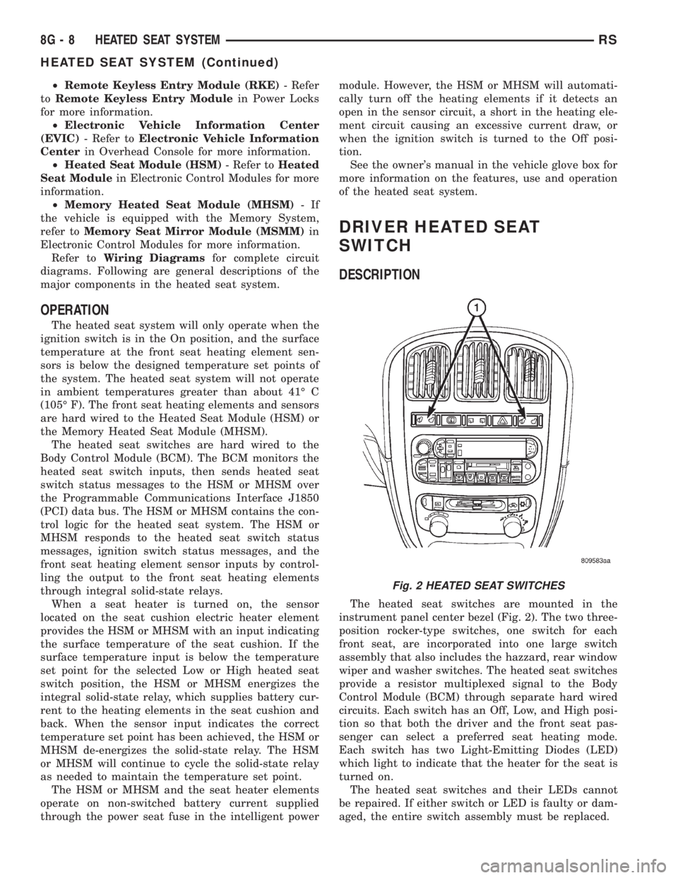
The heated seat switches are mounted in the
instrument panel center bezel (Fig. 2). The two three-
position rocker-type switches, one switch for each
front seat, are incorporated into one large switch
assembly that also includes the hazzard, rear window
wiper and washer switches. The heated seat switches
provide a resistor multiplexed signal to the Body
Control Module (BCM) through separate hard wired
circuits. Each switch has an Off, Low, and High posi-
tion so that both the driver and the front seat pas-
senger can select a preferred seat heating mode.
Each switch has two Light-Emitting Diodes (LED)
which light to indicate that the heater for the seat is
turned on.
The heated seat switches and their LEDs cannot
be repaired. If either switch or LED is faulty or dam-
aged, the entire switch assembly must be replaced.
Fig. 2 HEATED SEAT SWITCHES
8G - 8 HEATED SEAT SYSTEMRS
HEATED SEAT SYSTEM (Continued)
Page 2031 of 4284
trically and independently using the separate power
seat switches found on the outboard seat cushion
side shield of each front seat. See the owner's manual
in the vehicle glove box for more information on the
features, use and operation of the power seat system.
OPERATION - MEMORY SYSTEM
The Memory Seat/Mirror Module (MSMM) will
drive a maximum of 2 motors at a time in a given
direction. If conflicting directions are requested, the
priority for response will be as follows:
²Seat Track Rearward
²Seat Front Down
²Seat Rear Down
²Recliner Rearward
²Seat Track Forward
²Seat Front Up
²Seat Rear Up
²Recliner Forward
The inputs from these switches to the MSMM is a
current limited battery source fed by the MSMM.
This protects the MSMM printed circuit board traces
from acting as fuses. All of these switch contact
inputs to the MSMM are normally closed to ground,
except when actuated.
Soft stops are incorporated to prevent the motor
from being driven into a stall. Should the seat have
restricted travel, refer to Resetting Soft Stops in this
section.
See the owner's manual in the vehicle glove box for
more information on the features, use and operation
of the memory system. For diagnosis of the MSM, the
PCI data bus, or the other electronic modules on the
PCI data bus that provide inputs and outputs for the
memory system, the use of a DRBtscan tool and the
proper Diagnostic Procedures manual are recom-
mended.
ELECTRONIC VEHICLE INFORMATION CENTER
The Electronic Vehicle Information Center (EVIC)
serves as the user interface for the memory system.
It displays memory system status messages and pro-
vides the user with the means for enabling and dis-
abling the many customer programmable features
available on the vehicle, including those for the mem-
ory system.
See the owner's manual in the vehicle glove box for
more information on the features, use and operation
of the EVIC. Refer toElectronic Vehicle Informa-
tion Centerin Overhead Console Systems for more
information on the EVIC.
DIAGNOSIS AND TESTING - POWER SEAT
SYSTEM
Following are tests that will help to diagnose the
hard wired components and circuits of the power seatsystem. However, if the vehicle is also equipped with
the optional memory system, these tests may not
prove conclusive in the diagnosis of the driver side
power seat. In order to obtain conclusive testing of
the driver side power seat with the memory system
option, the Programmable Communications Interface
(PCI) data bus network and all of the electronic mod-
ules that provide inputs to, or receive outputs from
the memory system components must be checked.
The most reliable, efficient, and accurate means to
diagnose the driver side power seat with the memory
system option requires the use of a DRBtscan tool
and the proper Diagnostic Procedures manual. The
DRBtscan tool can provide confirmation that the
PCI data bus is functional, that all of the electronic
modules are sending and receiving the proper mes-
sages on the PCI data bus, and that the memory sys-
tem is receiving the proper hard wired inputs and
relaying the proper hard wired outputs to perform its
driver side power seat functions.
WARNING: SOME VEHICLES ARE EQUIPPED WITH
SEATBACK MOUNTED AIRBAGS (Fig. 1). BEFORE
ATTEMPTING TO DIAGNOSE OR SERVICE ANY
SEAT OR POWER SEAT SYSTEM COMPONENT
YOU MUST FIRST DISCONNECT AND ISOLATE THE
BATTERY NEGATIVE CABLE. THEN WAIT TWO MIN-
UTES FOR THE SYSTEM CAPACITOR TO DIS-
CHARGE BEFORE FURTHER SYSTEM SERVICE.
THIS IS THE ONLY SURE WAY TO DISABLE THE
AIRBAG SYSTEM. FAILURE TO DO SO COULD
RESULT IN ACCIDENTAL AIRBAG DEPLOYMENT
AND POSSIBLE PERSONAL INJURY.
Before any testing of the power seat system is
attempted, the battery should be fully-charged and
all of the power seat system wire harness connections
and pins cleaned and tightened to ensure proper cir-
cuit continuity and ground paths. For complete cir-
cuit diagrams, refer toPower Seatin Wiring
Diagrams.
With the dome lamp on, apply the power seat
switch in the direction of the failure. If the dome
lamp dims, the seat may be jamming. Check under
and behind the seat for binding or obstructions. If
the dome lamp does not dim, proceed with testing of
the individual components and circuits.
DIAGNOSIS AND TESTING - MEMORY SYSTEM
CHECK AND RESET SOFT STOPS
To check and reset the power memory seat soft
stops, use the power seat control switches to move
the seat in one direction to the end of travel, allow a
couple of seconds before re-energizing the seat in the
same direction until it stops and for three additional
seconds after it stops. (The amount the seat moved
RSPOWER SEATS8N-51
POWER SEATS (Continued)
Page 2099 of 4284
8W-02 COMPONENT INDEX
Component Page
A/C Compressor Clutch Relay........... 8Wa-42
A/C Compressor Clutch................ 8Wa-42
A/C-Heater Control................... 8Wa-42
A/C Pressure Sensor.................. 8Wa-42
Accelerator Pedal Position Sensor........ 8Wa-30
Accessory Relay...................... 8Wa-10
Airbags............................. 8Wa-43
Ambient Temp Sensor................. 8Wa-49
Antenna............................ 8Wa-47
ATC Remote Sensor................... 8Wa-42
Auto Shut Down Relay................. 8Wa-30
Auto Temp Control.................... 8Wa-42
Automatic Day/Night Mirror............ 8Wa-49
Autostick Switch..................... 8Wa-31
Back-Up Lamp Switch................. 8Wa-51
Battery Temperature Sensor............ 8Wa-20
Battery............................. 8Wa-20
Blend Door Actuators.................. 8Wa-42
Blower Motor Resistor................. 8Wa-42
Body Control Module.................. 8Wa-45
Boost Pressure Sensor................. 8Wa-30
B-Pillar Switches..................... 8Wa-61
Brake Fluid Level Switch............... 8Wa-40
Brake Lamp Switch................... 8Wa-51
Brake Transmission Shift Interlock
Solenoid.......................... 8Wa-31
Cabin Heater Assist................... 8Wa-30
Camshaft Position Sensor.............. 8Wa-30
CD Changer......................... 8Wa-47
Center High Mounted Stop Lamp........ 8Wa-51
Cinch/Release Motors.................. 8Wa-61
Clockspring................. 8Wa-33, 41, 43, 47
Clutch Pedal Interlock Switch Jumper..... 8Wa-10
Clutch Pedal Interlock Switch........... 8Wa-10
Clutch Pedal Upstop Switch............. 8Wa-30
Combination Relays................... 8Wa-54
Controller Antilock Brake.............. 8Wa-35
Crank Case Ventilation Heater.......... 8Wa-30
Crankshaft Position Sensor............. 8Wa-30
Cylinder Lock Switches................ 8Wa-39
Data Link Connector.................. 8Wa-18
Defogger Relay....................... 8Wa-48
Diagnostic Junction Port............... 8Wa-18
Dome Lamps........................ 8Wa-44
Door Ajar Switches.................... 8Wa-39
Door Courtesy Lamps.................. 8Wa-44
Door Lock Motor/Ajar Switches.......... 8Wa-61
Door Lock Switches................... 8Wa-61
Dosing Pump........................ 8Wa-30
Driver Heated Seat Module............. 8Wa-63
ECM/PCM Relay..................... 8Wa-30
EGR Solenoid........................ 8Wa-30Component Page
Electric Wiper De-Icer................. 8Wa-48
Engine Control Module................ 8Wa-30
Engine Coolant Temp Sensor............ 8Wa-30
Engine Oil Pressure Sensor............. 8Wa-30
Engine Oil Pressure Switch............. 8Wa-30
Engine Oil Temperature Sensor.......... 8Wa-30
EVAP/Purge Solenoid.................. 8Wa-30
Evaporator Temperature Sensor......... 8Wa-42
Floor Console Lamp................... 8Wa-44
Floor Console Power Outlet............. 8Wa-41
Fog Lamps.......................... 8Wa-50
Front Blower Module.................. 8Wa-42
Front Blower Motor Relay.............. 8Wa-42
Front Blower Motor................... 8Wa-42
Front Cigar Lighter................... 8Wa-41
Front Control Module.................. 8Wa-10
Front Fog Lamp Relay................. 8Wa-50
Front Intrusion Sensor................. 8Wa-39
Front Reading Lamps/Switch............ 8Wa-44
Front Washer Pump Motor.............. 8Wa-53
Front Wiper Hi/Low Relay.............. 8Wa-53
Front Wiper On/Off Relay.............. 8Wa-53
Fuel Heater Relay.................... 8Wa-10
Fuel Heater......................... 8Wa-30
Fuel Injectors........................ 8Wa-30
Fuel Pressure Sensor.................. 8Wa-30
Fuel Pressure Solenoid................. 8Wa-30
Fuel Pump Module.................... 8Wa-30
Fuel Pump Relay..................... 8Wa-30
Full Open Switches................... 8Wa-61
Fuselink............................ 8Wa-10
Fuses (IPM)......................... 8Wa-10
Generator........................... 8Wa-20
Glove Box Lamp...................... 8Wa-44
Glow Plug Relay...................... 8Wa-30
Glow Plugs.......................... 8Wa-30
Grounds............................ 8Wa-15
Halo Lamp.......................... 8Wa-44
Headlamp Leveling Motors............. 8Wa-50
Headlamp Switch..................... 8Wa-50
Headlamp Washer Pump Motor.......... 8Wa-53
Headlamp Washer Relay............... 8Wa-53
Headlamps.......................... 8Wa-50
Heated Seat Backs.................... 8Wa-63
Heated Seat Cushions................. 8Wa-63
High Beam Lamps.................... 8Wa-50
Hood Ajar Switch..................... 8Wa-39
Horn Relay.......................... 8Wa-41
Horn Switch......................... 8Wa-41
Horns.............................. 8Wa-41
Idle Air Control Motor................. 8Wa-30
Ignition Coil......................... 8Wa-30
RG8W-02 COMPONENT INDEX8Wa-02-1
Page 2309 of 4284
8W-44 INTERIOR LIGHTING
Component Page
A/C- Heater Control................. 8Wa-44-8
Accessory Relay..................... 8Wa-44-4
Auto Temp Control.................. 8Wa-44-8
Body Control Module..... 8Wa-44-2, 3, 4, 5, 6, 7, 8
Center Dome Lamp.................. 8Wa-44-5
Driver Door Courtesy Lamp........... 8Wa-44-2
Floor Console Lamp................. 8Wa-44-4
Front Cigar Lighter.................. 8Wa-44-7
Front Control Module................ 8Wa-44-4
Front Reading Lamps/Switch........ 8Wa-44-4, 5
Fuse 6 (IPM)....................... 8Wa-44-4
G200....................... 8Wa-44-2, 5, 7, 8
G300........................... 8Wa-44-2, 8
G301....................... 8Wa-44-2, 3, 5, 6
G302............................. 8Wa-44-4
G400............................. 8Wa-44-2
Glove Box Lamp.................... 8Wa-44-5
Halo Lamp........................ 8Wa-44-2
Headlamp Switch........... 8Wa-44-3, 5, 6, 7, 8
Instrument Cluster.................. 8Wa-44-7
Instrument Panel Switch Bank......... 8Wa-44-7
Intelligent Power Module............. 8Wa-44-4
Left Liftgate Flood Lamp............. 8Wa-44-2
Left Mid Reading Lamp.............. 8Wa-44-3
Left Rear Reading Lamp.............. 8Wa-44-3
Left Visor/Vanity Lamp............... 8Wa-44-6
Overhead Console................... 8Wa-44-5
Passenger Door Courtesy Lamp........ 8Wa-44-2
Power Mirror Switch................. 8Wa-44-8
Radio............................. 8Wa-44-7
Rear Auto Temp Control Switch........ 8Wa-44-8
Rear Blower Rear Control Switch....... 8Wa-44-8
Rear Dome Lamp................... 8Wa-44-5
Right Liftgate Flood Lamp............ 8Wa-44-2
Right Mid Reading Lamp............. 8Wa-44-3
Right Rear Reading Lamp............. 8Wa-44-3
Right Visor/Vanity Lamp.............. 8Wa-44-6
RG8W-44 INTERIOR LIGHTING8Wa-44-1
Page 2317 of 4284
8W-45 BODY CONTROL MODULE
Component Page
A/C-Heater Control.............. 8Wa-45-15, 18
Auto Temp Control.............. 8Wa-45-15, 18
Automatic Day/Night Mirror.......... 8Wa-45-11
Body Control Module . . 8Wa-45-2, 3, 4, 5, 6, 7, 8, 9,
10, 11, 12, 13, 14, 15, 16, 17, 18, 19
Center Dome Lamp............... 8Wa-45-9, 13
Clockspring....................... 8Wa-45-16
Controller Antilock Brake............ 8Wa-45-13
Diagnostic Junction Port............. 8Wa-45-12
Driver Door Courtesy Lamp.......... 8Wa-45-14
Driver Door Lock Switch.......... 8Wa-45-12, 14
Driver Heated Seat Module........... 8Wa-45-11
Floor Console Lamp................ 8Wa-45-13
Front Cigar Lighter................. 8Wa-45-16
Front Control Module................ 8Wa-45-3
Front Reading Lamps/Switch....... 8Wa-45-8, 13
Fuel Pump Module................. 8Wa-45-14
Fuse 14 (IPM)...................... 8Wa-45-3
Fuse 19 (IPM)...................... 8Wa-45-2
Fuse 20 (IPM)...................... 8Wa-45-2
Fuse 24 (IPM)...................... 8Wa-45-2
G301......................... 8Wa-45-5, 6, 8
Glove Box Lamp................... 8Wa-45-18
Halo Lamp....................... 8Wa-45-18
Headlamp Switch............. 8Wa-45-11, 15, 19
Hood Ajar Switch.................. 8Wa-45-12
Ignition Switch..................... 8Wa-45-3
Instrument Cluster.............. 8Wa-45-15, 18
Instrument Panel Switch Bank . . 8Wa-45-10, 11, 16,
18
Intelligent Power Module..... 8Wa-45-2, 3, 5, 6, 13
Left B-Pillar Switch................. 8Wa-45-9
Left Cylinder Lock Switch............ 8Wa-45-10
Left Front Door Lock Motor/Ajar Switch . 8Wa-45-4,
7
Left Liftgate Flood Lamp............ 8Wa-45-12
Left Mid Reading Lamp........... 8Wa-45-9, 14
Left Power Mirror.................. 8Wa-45-19
Left Rear Lamp Assembly........... 8Wa-45-5, 6
Left Rear Reading Lamp........... 8Wa-45-9, 14
Left Remote Radio Switch............ 8Wa-45-16
Left Repeater Lamp................ 8Wa-45-19
Left Sliding Door Control Module.... 8Wa-45-8, 10
Left Sliding Door Lock Motor.......... 8Wa-45-7
Left Sliding Door Lock Motor/Ajar Switch. 8Wa-45-7,
8
Left Stop/Turn Signal Relay........... 8Wa-45-5
Left Visor/Vanity Lamp.............. 8Wa-45-13
License Lamp...................... 8Wa-45-8
Liftgate Ajar Switch................ 8Wa-45-12
Liftgate Cinch/Release Motor......... 8Wa-45-12
Liftgate Cylinder Lock Switch.......... 8Wa-45-9Component Page
Memory Seat Switch................. 8Wa-45-4
Message Center.................... 8Wa-45-17
Multi- Function Switch.............. 8Wa-45-15
Name Brand Speaker Relay........... 8Wa-45-3
Overhead Console................ 8Wa-45-4, 11
Passenger Door Courtesy Lamp....... 8Wa-45-14
Passenger Door Lock Switch....... 8Wa-45-12, 14
Passenger Folding Mirror Relay....... 8Wa-45-19
Passenger Heated Seat Module........ 8Wa-45-11
Power Folding Mirror Switch......... 8Wa-45-19
Power Liftgate Module............... 8Wa-45-8
Power Mirror Switch................ 8Wa-45-15
Radio............................ 8Wa-45-16
Rear Auto Temp Control Switch.... 8Wa-45-10, 18
Rear Blower Rear Control Switch...... 8Wa-45-10
Rear Dome Lamp................... 8Wa-45-9
Rear Wiper Motor................... 8Wa-45-8
Remote Keyless Entry Module...... 8Wa-45-4, 15
Right B-Pillar Switch................ 8Wa-45-9
Right Combination Relay............. 8Wa-45-5
Right Cylinder Lock Switch........... 8Wa-45-10
Right Front Door Lock Motor/Ajar Switch. 8Wa-45-7,
9
Right Liftgate Flood Lamp........... 8Wa-45-12
Right Mid Reading Lamp.......... 8Wa-45-9, 14
Right Power Mirror................. 8Wa-45-19
Right Rear Lamp Assembly.......... 8Wa-45-5, 6
Right Rear Reading Lamp.......... 8Wa-45-9, 14
Right Remote Radio Switch........... 8Wa-45-16
Right Repeater Lamp............... 8Wa-45-19
Right Sliding Door Control Module . . . 8Wa-45-8, 10
Right Sliding Door Lock Motor......... 8Wa-45-7
Right Sliding Door Lock Motor/Ajar Switch. 8Wa-45-7,
8
Right Visor/Vanity Lamp............. 8Wa-45-13
Thatcham Alarm Module............. 8Wa-45-10
Traction Control Switch............. 8Wa-45-16
RG8W-45 BODY CONTROL MODULE8Wa-45-1