2001 CHRYSLER VOYAGER fuse chart
[x] Cancel search: fuse chartPage 1905 of 4284
OPERATION
There are three positions that can be selected with
each of the heated seat switches: Off, Low, or High.
When the left side of the switch rocker is fully
depressed, the Low position is selected and the high
position LED indicator illuminates. When the right
side of the switch rocker is fully depressed, the High
position is selected and the low position LED indica-
tor illuminates. When the switch rocker is moved to
its neutral position (middle), Off is selected and both
LED indicators are extinguished.
Both switches provide separate resistor multi-
plexed hard wire inputs to the BCM to indicate the
selected switch position. The BCM monitors the
switch inputs and sends heated seat switch status
messages to the Heated Seat Module (HSM) or the
Memory Heated Seat Module (MHSM) over the Pro-
grammable Communications Interface (PCI) data
bus. The HSM or MHSM responds to the heated seat
switch status messages by controlling the output to
the seat heater elements of the selected seat. The
Low heat position set point is about 36É C (97É F),
and the High heat position set point is about 41É C
(105É F).
DIAGNOSIS & TESTING - HEATED SEAT
SWITCH
For complete circuit diagrams, refer toWiring
Diagrams.
WARNING: ON VEHICLES EQUIPPED WITH AIR-
BAGS, REFER TO THE RESTRAINTS SECTION OF
THIS MANUAL BEFORE ATTEMPTING ANY STEER-
ING WHEEL, STEERING COLUMN, SEAT OR
INSTRUMENT PANEL COMPONENT DIAGNOSIS OR
SERVICE. FAILURE TO TAKE THE PROPER PRE-
CAUTIONS COULD RESULT IN ACCIDENTAL AIR-
BAG DEPLOYMENT AND POSSIBLE PERSONAL
INJURY.
(1) Check the fused ignition switch output (run)
fuse in the intelligent power module. If OK, go to
Step 2. If not OK, repair the shorted circuit or com-
ponent as required and replace the faulty fuse.
(2) Turn the ignition switch to the On position.
Check for battery voltage at the fused ignition switch
output (run) fuse in the intelligent power module. If
OK, go to Step 3. If not OK, repair the open fused
ignition switch output (run) circuit to the ignition
switch as required.
(3) Disconnect and isolate the battery negative
cable. Remove the center bezel from the instrument
panel and disconnect the instrument panel wire har-
ness connectors from the heated seat switch connec-
tor receptacle. Check for continuity between the
ground circuit cavity of the instrument panel wireharness connector for the inoperative heated seat
switch(es) and a good ground. There should be conti-
nuity. If OK, go to Step 4. If not OK, repair the open
ground circuit to ground as required.
(4) Reconnect the battery negative cable. Turn the
ignition switch to the On position. Check for battery
voltage at the fused ignition switch output (run) cir-
cuit cavity of the instrument panel wire harness con-
nector for the inoperative heated seat switch(es). If
OK, turn the ignition switch to the Off position, dis-
connect and isolate the battery negative cable, and go
to Step 5. If not OK, repair the open fused ignition
switch output (run) circuit to the intelligent power
module fuse as required.
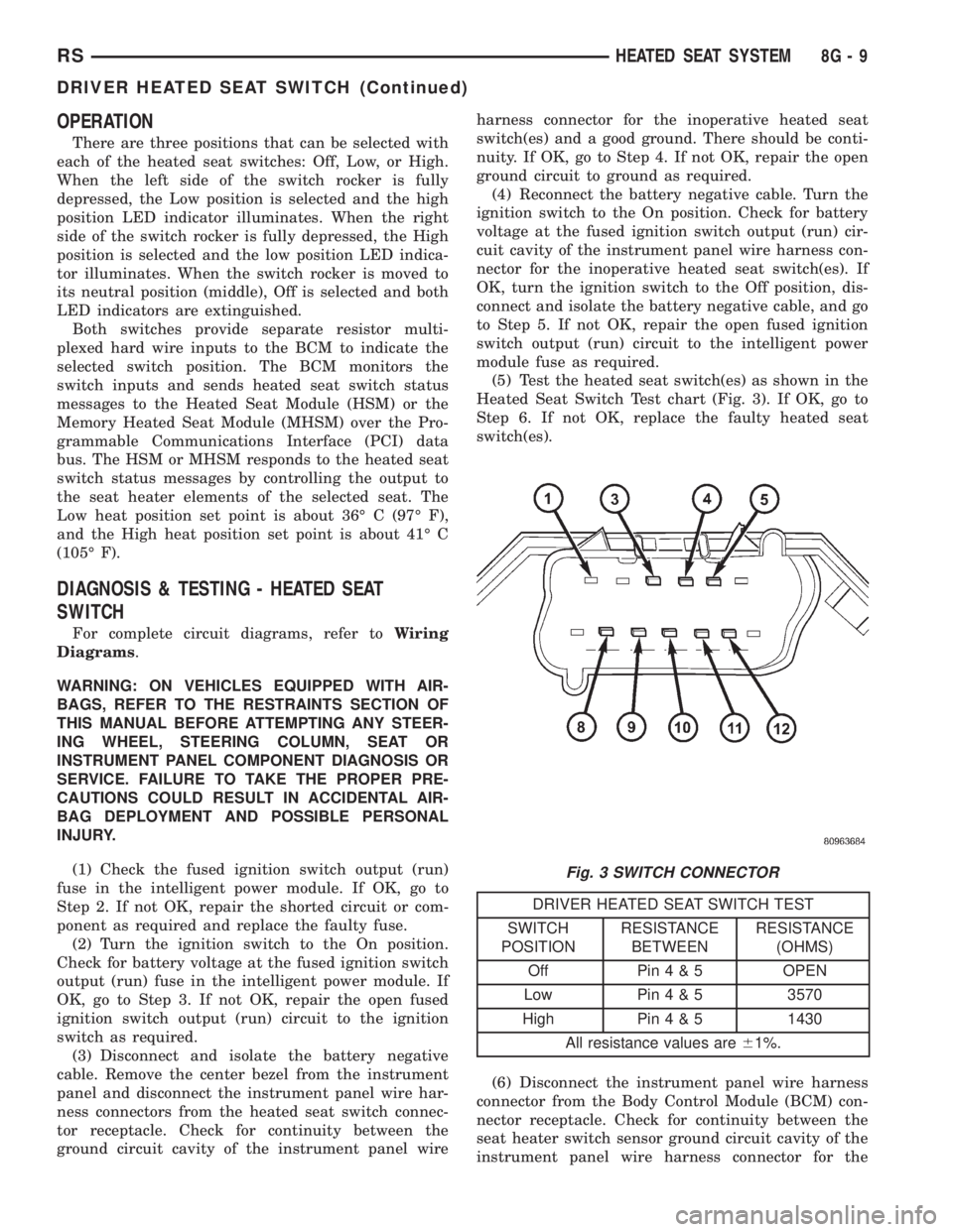
(5) Test the heated seat switch(es) as shown in the
Heated Seat Switch Test chart (Fig. 3). If OK, go to
Step 6. If not OK, replace the faulty heated seat
switch(es).
DRIVER HEATED SEAT SWITCH TEST
SWITCH
POSITIONRESISTANCE
BETWEENRESISTANCE
(OHMS)
Off Pin4&5OPEN
Low Pin4&53570
High Pin4&51430
All resistance values are61%.
(6) Disconnect the instrument panel wire harness
connector from the Body Control Module (BCM) con-
nector receptacle. Check for continuity between the
seat heater switch sensor ground circuit cavity of the
instrument panel wire harness connector for the
Fig. 3 SWITCH CONNECTOR
RSHEATED SEAT SYSTEM8G-9
DRIVER HEATED SEAT SWITCH (Continued)
Page 1908 of 4284
depressed, the Low position is selected and the high
position LED indicator illuminates. When the right
side of the switch rocker is fully depressed, the High
position is selected and the low position LED indica-
tor illuminates. When the switch rocker is moved to
its neutral position (middle), Off is selected and both
LED indicators are extinguished.
Both switches provide separate resistor multi-
plexed hard wire inputs to the BCM to indicate the
selected switch position. The BCM monitors the
switch inputs and sends heated seat switch status
messages to the Heated Seat Module (HSM) or the
Memory Heated Seat Module (MHSM) over the Pro-
grammable Communications Interface (PCI) data
bus. The HSM or MHSM responds to the heated seat
switch status messages by controlling the output to
the seat heater elements of the selected seat. The
Low heat position set point is about 36É C (97É F),
and the High heat position set point is about 41É C
(105É F).
DIAGNOSIS & TESTING - HEATED SEAT
SWITCH
For complete circuit diagrams, refer toWiring
Diagrams.
WARNING: ON VEHICLES EQUIPPED WITH AIR-
BAGS, REFER TO THE RESTRAINTS SECTION OF
THIS MANUAL BEFORE ATTEMPTING ANY STEER-
ING WHEEL, STEERING COLUMN, SEAT OR
INSTRUMENT PANEL COMPONENT DIAGNOSIS OR
SERVICE. FAILURE TO TAKE THE PROPER PRE-
CAUTIONS COULD RESULT IN ACCIDENTAL AIR-BAG DEPLOYMENT AND POSSIBLE PERSONAL
INJURY.
(1) Check the fused ignition switch output (run)
fuse in the intelligent power module. If OK, go to
Step 2. If not OK, repair the shorted circuit or com-
ponent as required and replace the faulty fuse.
(2) Turn the ignition switch to the On position.
Check for battery voltage at the fused ignition switch
output (run) fuse in the intelligent power module. If
OK, go to Step 3. If not OK, repair the open fused
ignition switch output (run) circuit to the ignition
switch as required.
(3) Disconnect and isolate the battery negative
cable. Remove the center bezel from the instrument
panel and disconnect the instrument panel wire har-
ness connectors from the heated seat switch connec-
tor receptacle. Check for continuity between the
ground circuit cavity of the instrument panel wire
harness connector for the inoperative heated seat
switch(es) and a good ground. There should be conti-
nuity. If OK, go to Step 4. If not OK, repair the open
ground circuit to ground as required.
(4) Reconnect the battery negative cable. Turn the
ignition switch to the On position. Check for battery
voltage at the fused ignition switch output (run) cir-
cuit cavity of the instrument panel wire harness con-
nector for the inoperative heated seat switch(es). If
OK, turn the ignition switch to the Off position, dis-
connect and isolate the battery negative cable, and go
to Step 5. If not OK, repair the open fused ignition
switch output (run) circuit to the intelligent power
module fuse as required.
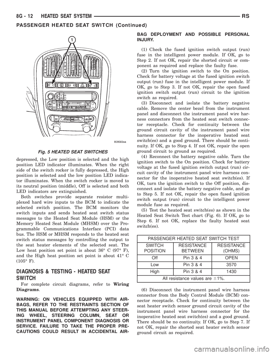
(5) Test the heated seat switch(es) as shown in the
Heated Seat Switch Test chart (Fig. 6). If OK, go to
Step 6. If not OK, replace the faulty heated seat
switch(es).
PASSENGER HEATED SEAT SWITCH TEST
SWITCH
POSITIONRESISTANCE
BETWEENRESISTANCE
(OHMS)
Off Pin3&4OPEN
Low Pin3&43570
High Pin3&41430
All resistance values are61%.
(6) Disconnect the instrument panel wire harness
connector from the Body Control Module (BCM) con-
nector receptacle. Check for continuity between the
seat heater switch sensor ground circuit cavity of the
instrument panel wire harness connector for the
inoperative heated seat switch(es) and a good ground.
There should be no continuity. If OK, go to Step 7. If
not OK, repair the shorted seat heater switch sensor
ground circuit as required.
Fig. 5 HEATED SEAT SWITCHES
8G - 12 HEATED SEAT SYSTEMRS
PASSENGER HEATED SEAT SWITCH (Continued)
Page 3676 of 4284
(1) Check the fuse (Fuse 10 - 40 ampere) in the
Intelligent Power Module (IPM). If OK, go to Step 2.
If not OK, repair the shorted circuit or component as
required and replace the faulty fuse.
(2) Turn the ignition switch to the On position. Be
certain that the heater-A/C control power is turned
on. Check for battery voltage at the fuse (Fuse 10 -
40 ampere) in the IPM. If OK, go to Step 3. If not
OK, proceed to diagnosis of the front blower motor
relay. (Refer to 24 - HEATING & AIR CONDITION-
ING/CONTROLS - FRONT/BLOWER MOTOR
RELAY - DIAGNOSIS AND TESTING).
(3) Turn the ignition switch to the Off position.
Disconnect and isolate the battery negative cable.
Disconnect the front HVAC wire harness connector
for the front blower motor resistor (Manual Temper-
ature Control) or the front blower power module
(Automatic Temperature Control) from the resistor or
module connector receptacle. Reconnect the battery
negative cable. Turn the ignition switch to the On
position. Be certain that the heater-A/C control
power is turned on. Check for battery voltage at the
fused front blower motor relay output circuit cavity
of the front HVAC wire harness connector for thefront blower motor resistor (MTC) or the front blower
power module (ATC). If OK, go to Step 4. If not OK,
repair the open fused front blower motor relay output
circuit to the IPM as required.
(4) Turn the ignition switch to the Off position.
Disconnect and isolate the battery negative cable.
Disconnect the front blower motor pigtail wire con-
nector from the connector receptacle of the front
blower motor resistor (MTC) or the front blower
power module (ATC). Use jumper wires to connect a
battery and ground feeds to the blower motor pigtail
wire connector. The blower motor should operate. If
OK with MTC, proceed to diagnosis of the front
blower motor resistor. (Refer to 24 - HEATING & AIR
CONDITIONING/CONTROLS - FRONT/BLOWER
MOTOR RESISTOR - DIAGNOSIS AND TESTING).
If OK with ATC, use a DRBIII scan tool to diagnose
the front blower power module. Refer to the appropri-
ate diagnostic information. If not OK with MTC or
ATC, replace the faulty front blower motor.
BLOWER MOTOR NOISE OR VIBRATION
Refer to the Blower Motor Noise/Vibration Diagno-
sis chart (Fig. 8).
24 - 46 DISTRIBUTION - FRONTRS
BLOWER MOTOR (Continued)
Page 3686 of 4284
system control switch on the front heater-A/C control
is not in the Off position. The blower motor can only
be turned off by turning off the rear system at the
front heater-A/C control. The blower motor receives
battery current whenever the rear blower motor
relay is energized. The rear blower motor relay out-
put circuit is protected by a fuse in the Intelligent
Power Module (IPM) located in the engine compart-
ment near the battery. In the MTC system, the
blower motor speed is controlled by regulating the
path to ground through the blower control switch and
the blower motor resistor. In the ATC system, the
blower motor speed is controlled by an electronic
blower power module, which uses a pulse width mod-
ulated input from the ATC module and feedback from
the blower motor to regulate the blower motor
ground path it provides. The blower motor and wheel
are used to control the velocity of air moving through
the rear heater-A/C unit housing. The blower motor
controls the velocity of the air flowing through the
rear heater-A/C housing by spinning the blower
wheel within the housing at the selected speed or, in
the ATC system, at the selected or programmed
speed.
DIAGNOSIS AND TESTING - REAR BLOWER
MOTOR
BLOWER MOTOR INOPERATIVE
(1) Check the fuse (Fuse 12 - 25 ampere) in the
Intelligent Power Module (IPM). If OK, go to Step 2.
If not OK, repair the shorted circuit or component as
required and replace the faulty fuse.
(2) Turn the ignition switch to the On position. Be
certain that the rear heater-A/C control power is
turned on. Check for battery voltage at the fuse
(Fuse 12 - 25 ampere) in the IPM. If OK, go to Step
3. If not OK, proceed to diagnosis of the rear blower
motor relay. (Refer to 24 - HEATING & AIR CONDI-TIONING/CONTROLS - REAR/BLOWER MOTOR
RELAY - DIAGNOSIS AND TESTING).
(3) Turn the ignition switch to the Off position.
Disconnect and isolate the battery negative cable.
Disconnect the rear HVAC wire harness connector for
the rear blower motor resistor (Manual Temperature
Control) or the rear blower power module (Automatic
Temperature Control) from the resistor or module
connector receptacle. Reconnect the battery negative
cable. Turn the ignition switch to the On position. Be
certain that the rear heater-A/C control power is
turned on. Check for battery voltage at the fused
rear blower motor relay output circuit cavity of the
rear HVAC wire harness connector for the rear
blower motor resistor (MTC) or the rear blower
power module (ATC). If OK, go to Step 4. If not OK,
repair the open fused front blower motor relay output
circuit to the IPM as required.
(4) Turn the ignition switch to the Off position.
Disconnect and isolate the battery negative cable.
Disconnect the rear blower motor pigtail wire connec-
tor from the take out and connector of the rear
HVAC wire harness (MTC) or the connector recepta-
cle of the rear blower power module (ATC). Use
jumper wires to connect a battery and ground feeds
to the blower motor pigtail wire connector. The
blower motor should operate. If OK with MTC, pro-
ceed to diagnosis of the rear blower motor resistor.
(Refer to 24 - HEATING & AIR CONDITIONING/
CONTROLS - REAR/BLOWER MOTOR RESISTOR -
DIAGNOSIS AND TESTING). If OK with ATC, use a
DRBIII scan tool to diagnose the rear blower power
module. Refer to the appropriate diagnostic informa-
tion. If not OK with MTC or ATC, replace the faulty
rear blower motor.
BLOWER MOTOR NOISE OR VIBRATION
Refer to the Blower Motor Noise/Vibration Diagno-
sis chart (Fig. 4).
24 - 56 DISTRIBUTION - REARRS
BLOWER MOTOR (Continued)
Page 3793 of 4284
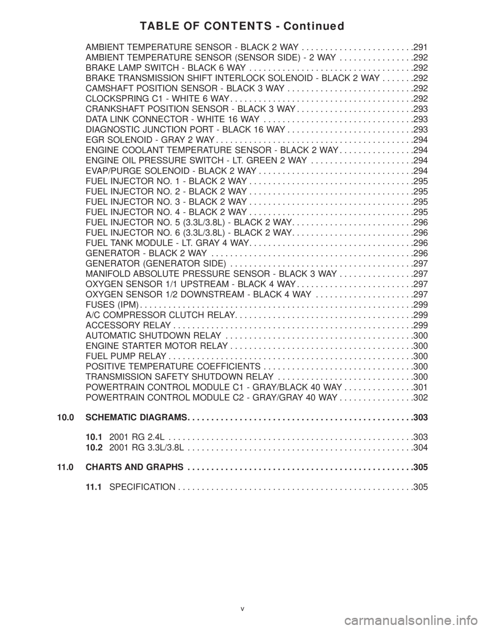
TABLE OF CONTENTS - Continued
AMBIENT TEMPERATURE SENSOR - BLACK 2 WAY........................291
AMBIENT TEMPERATURE SENSOR (SENSOR SIDE)-2WAY................292
BRAKE LAMP SWITCH - BLACK 6 WAY...................................292
BRAKE TRANSMISSION SHIFT INTERLOCK SOLENOID - BLACK 2 WAY.......292
CAMSHAFT POSITION SENSOR - BLACK 3 WAY...........................292
CLOCKSPRING C1 - WHITE 6 WAY.......................................292
CRANKSHAFT POSITION SENSOR - BLACK 3 WAY.........................293
DATA LINK CONNECTOR - WHITE 16 WAY................................293
DIAGNOSTIC JUNCTION PORT - BLACK 16 WAY...........................293
EGR SOLENOID - GRAY 2 WAY..........................................294
ENGINE COOLANT TEMPERATURE SENSOR - BLACK 2 WAY................294
ENGINE OIL PRESSURE SWITCH - LT. GREEN 2 WAY......................294
EVAP/PURGE SOLENOID - BLACK 2 WAY.................................294
FUEL INJECTOR NO. 1 - BLACK 2 WAY...................................295
FUEL INJECTOR NO. 2 - BLACK 2 WAY...................................295
FUEL INJECTOR NO. 3 - BLACK 2 WAY...................................295
FUEL INJECTOR NO. 4 - BLACK 2 WAY...................................295
FUEL INJECTOR NO. 5 (3.3L/3.8L) - BLACK 2 WAY..........................296
FUEL INJECTOR NO. 6 (3.3L/3.8L) - BLACK 2 WAY..........................296
FUEL TANK MODULE - LT. GRAY 4 WAY...................................296
GENERATOR - BLACK 2 WAY...........................................296
GENERATOR (GENERATOR SIDE).......................................297
MANIFOLD ABSOLUTE PRESSURE SENSOR - BLACK 3 WAY................297
OXYGEN SENSOR 1/1 UPSTREAM - BLACK 4 WAY.........................297
OXYGEN SENSOR 1/2 DOWNSTREAM - BLACK 4 WAY.....................297
FUSES (IPM)..........................................................299
A/C COMPRESSOR CLUTCH RELAY......................................299
ACCESSORY RELAY...................................................299
AUTOMATIC SHUTDOWN RELAY........................................300
ENGINE STARTER MOTOR RELAY.......................................300
FUEL PUMP RELAY....................................................300
POSITIVE TEMPERATURE COEFFICIENTS................................300
TRANSMISSION SAFETY SHUTDOWN RELAY.............................300
POWERTRAIN CONTROL MODULE C1 - GRAY/BLACK 40 WAY...............301
POWERTRAIN CONTROL MODULE C2 - GRAY/GRAY 40 WAY................302
10.0 SCHEMATIC DIAGRAMS................................................303
10.12001 RG 2.4L....................................................303
10.22001 RG 3.3L/3.8L................................................304
11.0 CHARTS AND GRAPHS................................................305
11.1SPECIFICATION..................................................305
v