2001 CHRYSLER VOYAGER torque
[x] Cancel search: torquePage 3 of 4284
FOREWORD
The information contained in this service manual has been prepared for the professional automotive tech-
nician involved in daily repair operations. Information describing the operation and use of standard and
optional equipment is included in the Owner's Manual provided with the vehicle.
Information in this manual is divided into groups. These groups contain description, operation, diagnosis,
testing, adjustments, removal, installation, disassembly, and assembly procedures for the systems and compo-
nents. To assist in locating a group title page, use the Group Tab Locator by clicking to the following page. The
first page of the group has a contents section that lists major topics within the group.
A Service Manual Comment form is included at the rear of this manual. Use the form to provide
DaimlerChrysler Corporation with your comments and suggestions.
Tightening torques are provided as a specific value throughout this manual. This value represents the
midpoint of the acceptable engineering torque range for a given fastener application. These torque values are
intended for use in service assembly and installation procedures using the correct OEM fasteners. When
replacing fasteners, always use the same type (part number) fastener as removed.
DaimlerChrysler Corporation reserves the right to change testing procedures, specifications, diagnosis,
repair methods, or vehicle wiring at any time without prior notice or incurring obligation.
Page 1017 of 4284
Verification Tests
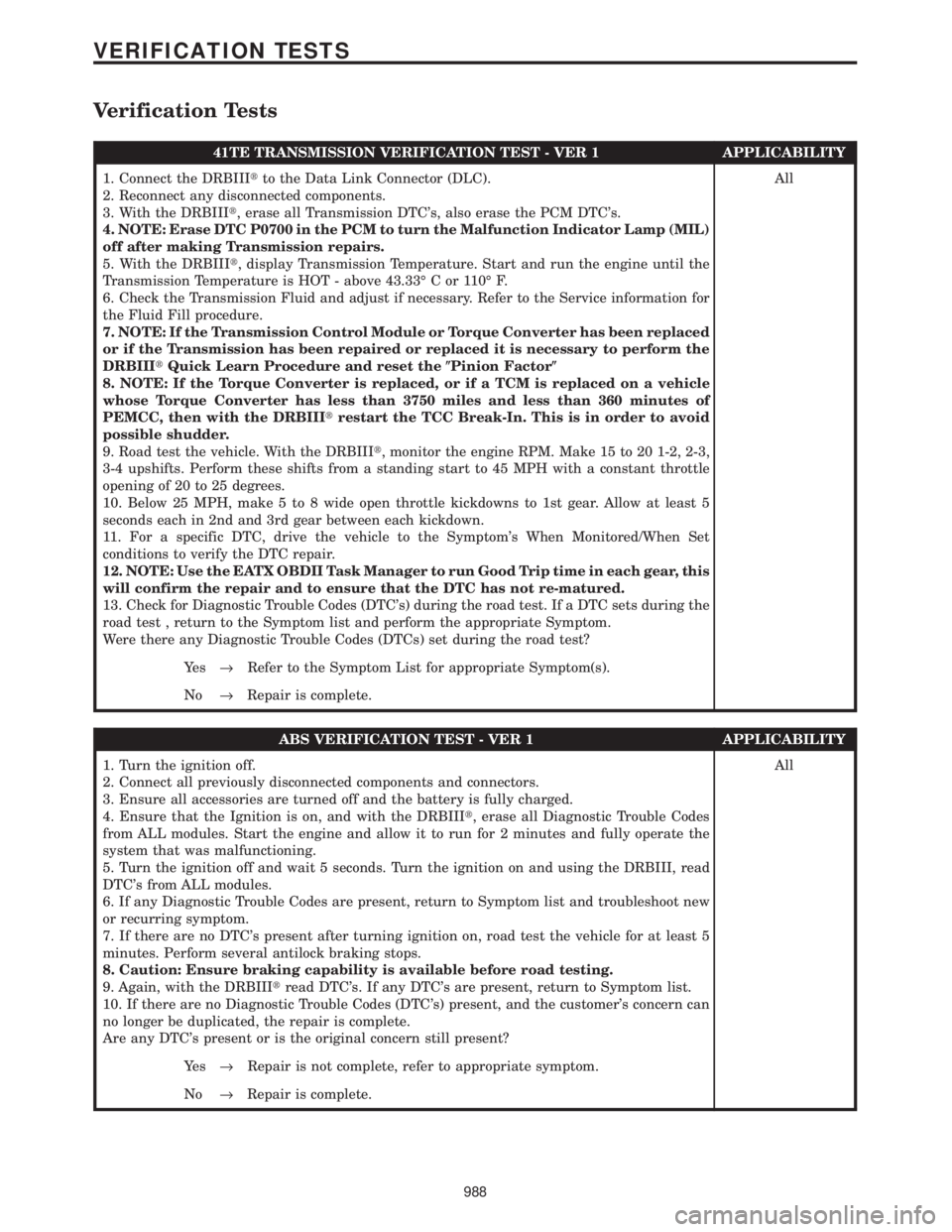
41TE TRANSMISSION VERIFICATION TEST - VER 1 APPLICABILITY
1. Connect the DRBIIItto the Data Link Connector (DLC).
2. Reconnect any disconnected components.
3. With the DRBIIIt, erase all Transmission DTC's, also erase the PCM DTC's.
4. NOTE: Erase DTC P0700 in the PCM to turn the Malfunction Indicator Lamp (MIL)
off after making Transmission repairs.
5. With the DRBIIIt, display Transmission Temperature. Start and run the engine until the
Transmission Temperature is HOT - above 43.33É C or 110É F.
6. Check the Transmission Fluid and adjust if necessary. Refer to the Service information for
the Fluid Fill procedure.
7. NOTE: If the Transmission Control Module or Torque Converter has been replaced
or if the Transmission has been repaired or replaced it is necessary to perform the
DRBIIItQuick Learn Procedure and reset the(Pinion Factor(
8. NOTE: If the Torque Converter is replaced, or if a TCM is replaced on a vehicle
whose Torque Converter has less than 3750 miles and less than 360 minutes of
PEMCC, then with the DRBIIItrestart the TCC Break-In. This is in order to avoid
possible shudder.
9. Road test the vehicle. With the DRBIIIt, monitor the engine RPM. Make 15 to 20 1-2, 2-3,
3-4 upshifts. Perform these shifts from a standing start to 45 MPH with a constant throttle
opening of 20 to 25 degrees.
10. Below 25 MPH, make 5 to 8 wide open throttle kickdowns to 1st gear. Allow at least 5
seconds each in 2nd and 3rd gear between each kickdown.
11. For a specific DTC, drive the vehicle to the Symptom's When Monitored/When Set
conditions to verify the DTC repair.
12. NOTE: Use the EATX OBDII Task Manager to run Good Trip time in each gear, this
will confirm the repair and to ensure that the DTC has not re-matured.
13. Check for Diagnostic Trouble Codes (DTC's) during the road test. If a DTC sets during the
road test , return to the Symptom list and perform the appropriate Symptom.
Were there any Diagnostic Trouble Codes (DTCs) set during the road test?All
Ye s®Refer to the Symptom List for appropriate Symptom(s).
No®Repair is complete.
ABS VERIFICATION TEST - VER 1 APPLICABILITY
1. Turn the ignition off.
2. Connect all previously disconnected components and connectors.
3. Ensure all accessories are turned off and the battery is fully charged.
4. Ensure that the Ignition is on, and with the DRBIIIt, erase all Diagnostic Trouble Codes
from ALL modules. Start the engine and allow it to run for 2 minutes and fully operate the
system that was malfunctioning.
5. Turn the ignition off and wait 5 seconds. Turn the ignition on and using the DRBIII, read
DTC's from ALL modules.
6. If any Diagnostic Trouble Codes are present, return to Symptom list and troubleshoot new
or recurring symptom.
7. If there are no DTC's present after turning ignition on, road test the vehicle for at least 5
minutes. Perform several antilock braking stops.
8. Caution: Ensure braking capability is available before road testing.
9. Again, with the DRBIIItread DTC's. If any DTC's are present, return to Symptom list.
10. If there are no Diagnostic Trouble Codes (DTC's) present, and the customer's concern can
no longer be duplicated, the repair is complete.
Are any DTC's present or is the original concern still present?All
Ye s®Repair is not complete, refer to appropriate symptom.
No®Repair is complete.
988
VERIFICATION TESTS
Page 1101 of 4284
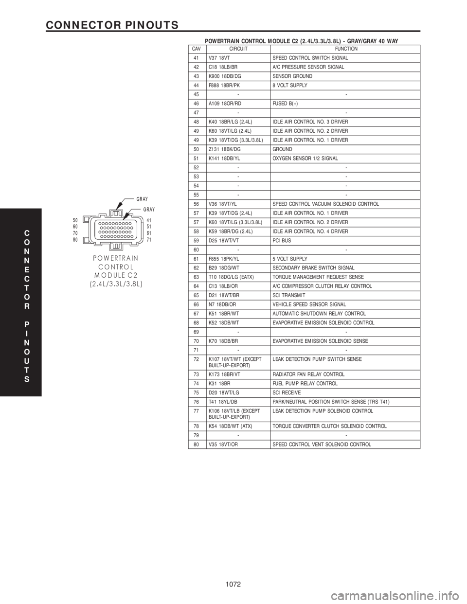
POWERTRAIN CONTROL MODULE C2 (2.4L/3.3L/3.8L) - GRAY/GRAY 40 WAYCAV CIRCUIT FUNCTION
41 V37 18VT SPEED CONTROL SWITCH SIGNAL
42 C18 18LB/BR A/C PRESSURE SENSOR SIGNAL
43 K900 18DB/DG SENSOR GROUND
44 F888 18BR/PK 8 VOLT SUPPLY
45 - -
46 A109 18OR/RD FUSED B(+)
47 - -
48 K40 18BR/LG (2.4L) IDLE AIR CONTROL NO. 3 DRIVER
49 K60 18VT/LG (2.4L) IDLE AIR CONTROL NO. 2 DRIVER
49 K39 18VT/DG (3.3L/3.8L) IDLE AIR CONTROL NO. 1 DRIVER
50 Z131 18BK/DG GROUND
51 K141 18DB/YL OXYGEN SENSOR 1/2 SIGNAL
52 - -
53 - -
54 - -
55 - -
56 V36 18VT/YL SPEED CONTROL VACUUM SOLENOID CONTROL
57 K39 18VT/DG (2.4L) IDLE AIR CONTROL NO. 1 DRIVER
57 K60 18VT/LG (3.3L/3.8L) IDLE AIR CONTROL NO. 2 DRIVER
58 K59 18BR/DG (2.4L) IDLE AIR CONTROL NO. 4 DRIVER
59 D25 18WT/VT PCI BUS
60 - -
61 F855 18PK/YL 5 VOLT SUPPLY
62 B29 18DG/WT SECONDARY BRAKE SWITCH SIGNAL
63 T10 18DG/LG (EATX) TORQUE MANAGEMENT REQUEST SENSE
64 C13 18LB/OR A/C COMPRESSOR CLUTCH RELAY CONTROL
65 D21 18WT/BR SCI TRANSMIT
66 N7 18DB/OR VEHICLE SPEED SENSOR SIGNAL
67 K51 18BR/WT AUTOMATIC SHUTDOWN RELAY CONTROL
68 K52 18DB/WT EVAPORATIVE EMISSION SOLENOID CONTROL
69 - -
70 K70 18DB/BR EVAPORATIVE EMISSION SOLENOID SENSE
71 - -
72 K107 18VT/WT (EXCEPT
BUILT-UP-EXPORT)LEAK DETECTION PUMP SWITCH SENSE
73 K173 18BR/VT RADIATOR FAN RELAY CONTROL
74 K31 18BR FUEL PUMP RELAY CONTROL
75 D20 18WT/LG SCI RECEIVE
76 T41 18YL/DB PARK/NEUTRAL POSITION SWITCH SENSE (TRS T41)
77 K106 18VT/LB (EXCEPT
BUILT-UP-EXPORT)LEAK DETECTION PUMP SOLENOID CONTROL
78 K54 18DB/WT (ATX) TORQUE CONVERTER CLUTCH SOLENOID CONTROL
79 - -
80 V35 18VT/OR SPEED CONTROL VENT SOLENOID CONTROL
C
O
N
N
E
C
T
O
R
P
I
N
O
U
T
S
1072
CONNECTOR PINOUTS
Page 1114 of 4284
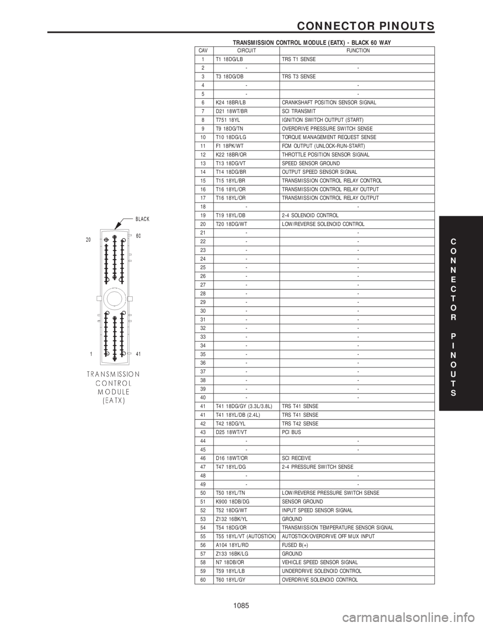
TRANSMISSION CONTROL MODULE (EATX) - BLACK 60 WAYCAV CIRCUIT FUNCTION
1 T1 18DG/LB TRS T1 SENSE
2- -
3 T3 18DG/DB TRS T3 SENSE
4- -
5- -
6 K24 18BR/LB CRANKSHAFT POSITION SENSOR SIGNAL
7 D21 18WT/BR SCI TRANSMIT
8 T751 18YL IGNITION SWITCH OUTPUT (START)
9 T9 18DG/TN OVERDRIVE PRESSURE SWITCH SENSE
10 T10 18DG/LG TORQUE MANAGEMENT REQUEST SENSE
11 F1 18PK/WT FCM OUTPUT (UNLOCK-RUN-START)
12 K22 18BR/OR THROTTLE POSITION SENSOR SIGNAL
13 T13 18DG/VT SPEED SENSOR GROUND
14 T14 18DG/BR OUTPUT SPEED SENSOR SIGNAL
15 T15 18YL/BR TRANSMISSION CONTROL RELAY CONTROL
16 T16 18YL/OR TRANSMISSION CONTROL RELAY OUTPUT
17 T16 18YL/OR TRANSMISSION CONTROL RELAY OUTPUT
18 - -
19 T19 18YL/DB 2-4 SOLENOID CONTROL
20 T20 18DG/WT LOW/REVERSE SOLENOID CONTROL
21 - -
22 - -
23 - -
24 - -
25 - -
26 - -
27 - -
28 - -
29 - -
30 - -
31 - -
32 - -
33 - -
34 - -
35 - -
36 - -
37 - -
38 - -
39 - -
40 - -
41 T41 18DG/GY (3.3L/3.8L) TRS T41 SENSE
41 T41 18YL/DB (2.4L) TRS T41 SENSE
42 T42 18DG/YL TRS T42 SENSE
43 D25 18WT/VT PCI BUS
44 - -
45 - -
46 D16 18WT/OR SCI RECEIVE
47 T47 18YL/DG 2-4 PRESSURE SWITCH SENSE
48 - -
49 - -
50 T50 18YL/TN LOW/REVERSE PRESSURE SWITCH SENSE
51 K900 18DB/DG SENSOR GROUND
52 T52 18DG/WT INPUT SPEED SENSOR SIGNAL
53 Z132 16BK/YL GROUND
54 T54 18DG/OR TRANSMISSION TEMPERATURE SENSOR SIGNAL
55 T55 18YL/VT (AUTOSTICK) AUTOSTICK/OVERDRIVE OFF MUX INPUT
56 A104 18YL/RD FUSED B(+)
57 Z133 16BK/LG GROUND
58 N7 18DB/OR VEHICLE SPEED SENSOR SIGNAL
59 T59 18YL/LB UNDERDRIVE SOLENOID CONTROL
60 T60 18YL/GY OVERDRIVE SOLENOID CONTROL
C
O
N
N
E
C
T
O
R
P
I
N
O
U
T
S
1085
CONNECTOR PINOUTS
Page 1469 of 4284
INTRODUCTION
TABLE OF CONTENTS
page page
VEHICLE SAFETY CERTIFICATION LABEL
DESCRIPTION............................1
VEHICLE IDENTIFICATION NUMBER
DESCRIPTION............................1
VECI LABEL
DESCRIPTION............................3
BODY CODE PLATE
DESCRIPTION............................3
INTERNATIONAL SYMBOLS
DESCRIPTION............................4FASTENER IDENTIFICATION
DESCRIPTION............................5
FASTENER USAGE
DESCRIPTION............................5
METRIC SYSTEM
DESCRIPTION............................8
TORQUE REFERENCES
DESCRIPTION...........................10
VEHICLE SAFETY
CERTIFICATION LABEL
DESCRIPTION
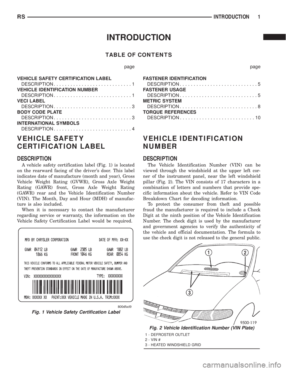
A vehicle safety certification label (Fig. 1) is located
on the rearward facing of the driver's door. This label
indicates date of manufacture (month and year), Gross
Vehicle Weight Rating (GVWR), Gross Axle Weight
Rating (GAWR) front, Gross Axle Weight Rating
(GAWR) rear and the Vehicle Identification Number
(VIN). The Month, Day and Hour (MDH) of manufac-
ture is also included.
When it is necessary to contact the manufacturer
regarding service or warranty, the information on the
Vehicle Safety Certification Label would be required.
VEHICLE IDENTIFICATION
NUMBER
DESCRIPTION
The Vehicle Identification Number (VIN) can be
viewed through the windshield at the upper left cor-
ner of the instrument panel, near the left windshield
pillar (Fig. 2). The VIN consists of 17 characters in a
combination of letters and numbers that provide spe-
cific information about the vehicle. Refer to VIN Code
Breakdown Chart for decoding information.
To protect the consumer from theft and possible
fraud the manufacturer is required to include a Check
Digit at the ninth position of the Vehicle Identification
Number. The check digit is used by the manufacturer
and government agencies to verify the authenticity of
the vehicle and official documentation. The formula to
use the check digit is not released to the general public.
Fig. 1 Vehicle Safety Certification Label
Fig. 2 Vehicle Identification Number (VIN Plate)
1 - DEFROSTER OUTLET
2 - VIN #
3 - HEATED WINDSHIELD GRID
RSINTRODUCTION1
Page 1473 of 4284
FASTENER IDENTIFICATION
DESCRIPTION
The SAE bolt strength grades range from grade 2
to grade 8. The higher the grade number, the greater
the bolt strength. Identification is determined by the
line marks on the top of each bolt head. The actual
bolt strength grade corresponds to the number of line
marks plus 2. The most commonly used metric bolt
strength classes are 9.8 and 10.9. The metric
strength class identification number is imprinted on
the head of the bolt. The higher the class number,
the greater the bolt strength. Some metric nuts are
imprinted with a single-digit strength class on the
nut face. Refer to the Fastener Identification and
Fastener Strength Charts.
FASTENER USAGE
DESCRIPTION - FASTENER USAGE
WARNING: USE OF AN INCORRECT FASTENER
MAY RESULT IN COMPONENT DAMAGE OR PER-
SONAL INJURY.
Figure art, specifications and torque references in
this Service Manual are identified in metric and SAE
format.
During any maintenance or repair procedures, it is
important to salvage all fasteners (nuts, bolts, etc.)
for reassembly. If the fastener is not salvageable, a
fastener of equivalent specification must be used.
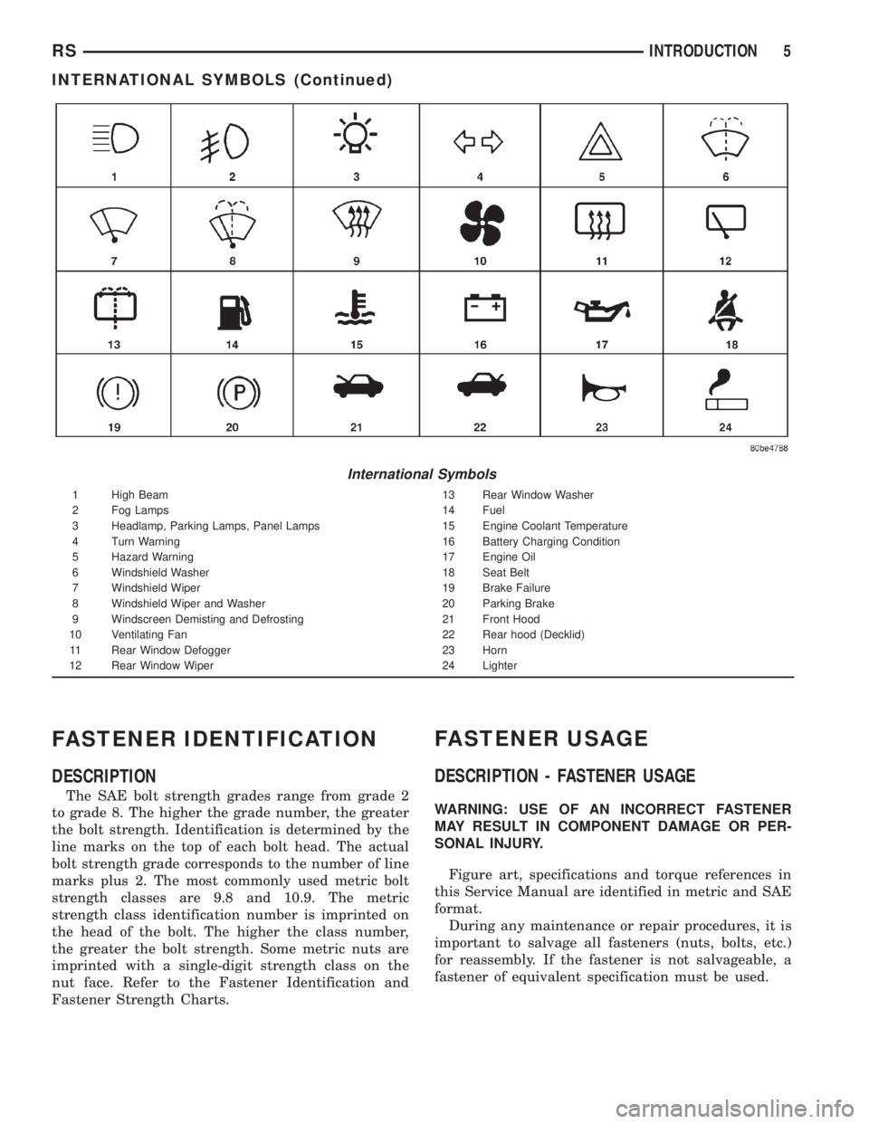
International Symbols
1 High Beam 13 Rear Window Washer
2 Fog Lamps 14 Fuel
3 Headlamp, Parking Lamps, Panel Lamps 15 Engine Coolant Temperature
4 Turn Warning 16 Battery Charging Condition
5 Hazard Warning 17 Engine Oil
6 Windshield Washer 18 Seat Belt
7 Windshield Wiper 19 Brake Failure
8 Windshield Wiper and Washer 20 Parking Brake
9 Windscreen Demisting and Defrosting 21 Front Hood
10 Ventilating Fan 22 Rear hood (Decklid)
11 Rear Window Defogger 23 Horn
12 Rear Window Wiper 24 Lighter
RSINTRODUCTION5
INTERNATIONAL SYMBOLS (Continued)
Page 1476 of 4284
DESCRIPTION - THREADED HOLE REPAIR
Most stripped threaded holes can be repaired using
a Helicoilt. Follow the vehicle or Helicoiltrecommen-
dations for application and repair procedures.
METRIC SYSTEM
DESCRIPTION - METRIC SYSTEM
The metric system is based on quantities of one,
ten, one hundred, one thousand and one million .
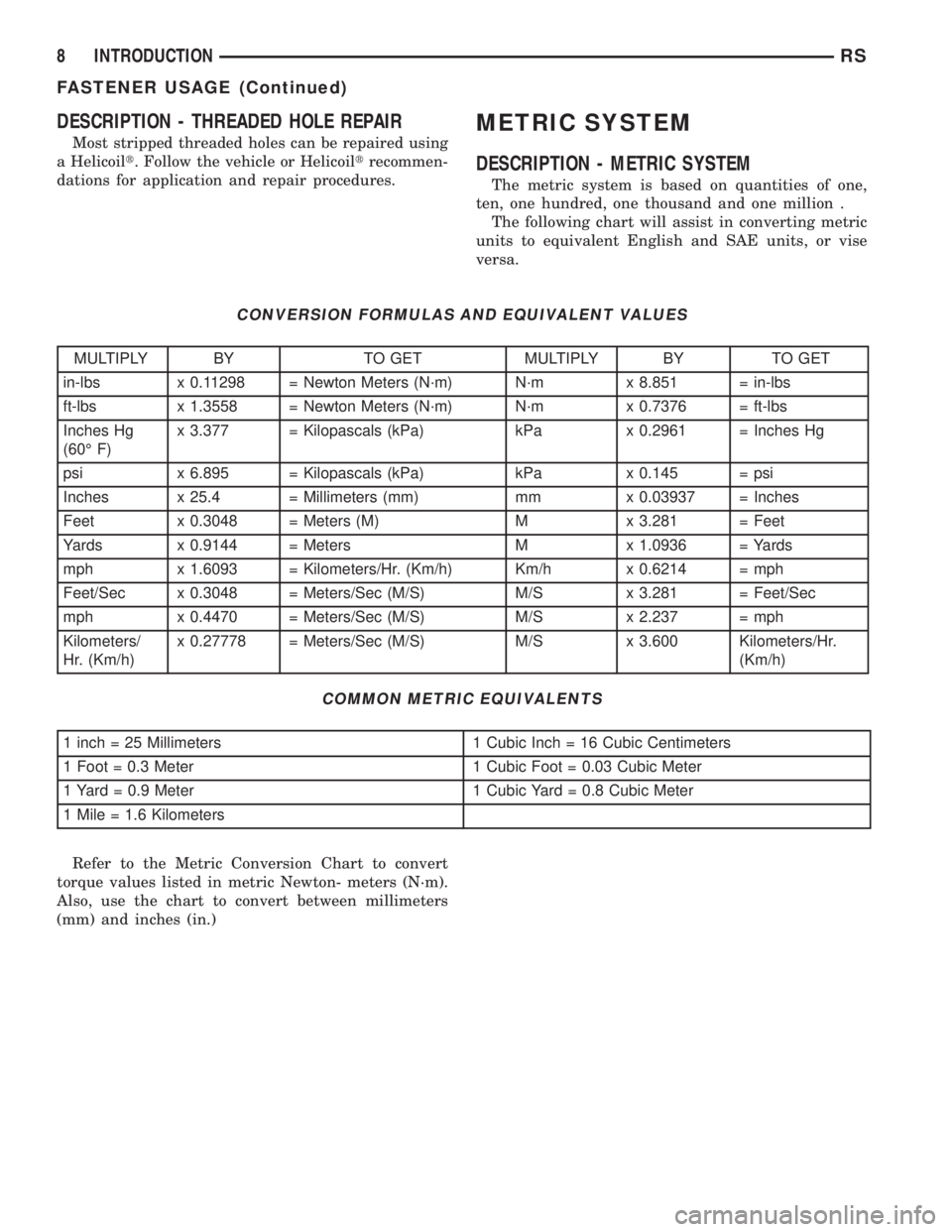
The following chart will assist in converting metric
units to equivalent English and SAE units, or vise
versa.
CONVERSION FORMULAS AND EQUIVALENT VALUES
MULTIPLY BY TO GET MULTIPLY BY TO GET
in-lbs x 0.11298 = Newton Meters (N´m) N´m x 8.851 = in-lbs
ft-lbs x 1.3558 = Newton Meters (N´m) N´m x 0.7376 = ft-lbs
Inches Hg
(60É F)x 3.377 = Kilopascals (kPa) kPa x 0.2961 = Inches Hg
psi x 6.895 = Kilopascals (kPa) kPa x 0.145 = psi
Inches x 25.4 = Millimeters (mm) mm x 0.03937 = Inches
Feet x 0.3048 = Meters (M) M x 3.281 = Feet
Yards x 0.9144 = Meters M x 1.0936 = Yards
mph x 1.6093 = Kilometers/Hr. (Km/h) Km/h x 0.6214 = mph
Feet/Sec x 0.3048 = Meters/Sec (M/S) M/S x 3.281 = Feet/Sec
mph x 0.4470 = Meters/Sec (M/S) M/S x 2.237 = mph
Kilometers/
Hr. (Km/h)x 0.27778 = Meters/Sec (M/S) M/S x 3.600 Kilometers/Hr.
(Km/h)
COMMON METRIC EQUIVALENTS
1 inch = 25 Millimeters 1 Cubic Inch = 16 Cubic Centimeters
1 Foot = 0.3 Meter 1 Cubic Foot = 0.03 Cubic Meter
1 Yard = 0.9 Meter 1 Cubic Yard = 0.8 Cubic Meter
1 Mile = 1.6 Kilometers
Refer to the Metric Conversion Chart to convert
torque values listed in metric Newton- meters (N´m).
Also, use the chart to convert between millimeters
(mm) and inches (in.)
8 INTRODUCTIONRS
FASTENER USAGE (Continued)
Page 1478 of 4284
TORQUE REFERENCES
DESCRIPTION
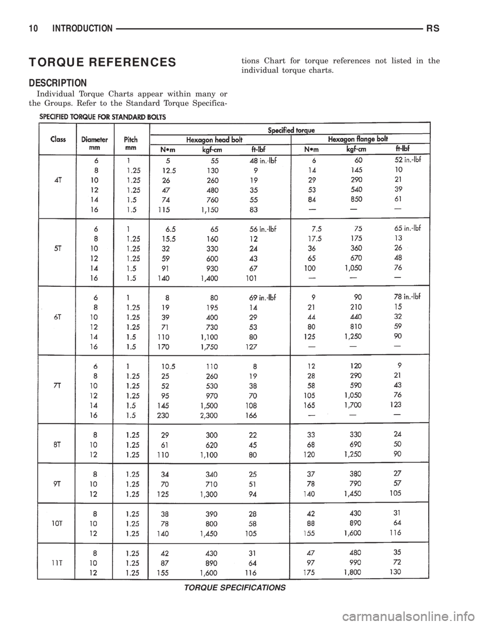
Individual Torque Charts appear within many or
the Groups. Refer to the Standard Torque Specifica-tions Chart for torque references not listed in the
individual torque charts.
TORQUE SPECIFICATIONS
10 INTRODUCTIONRS