Page 4259 of 4284

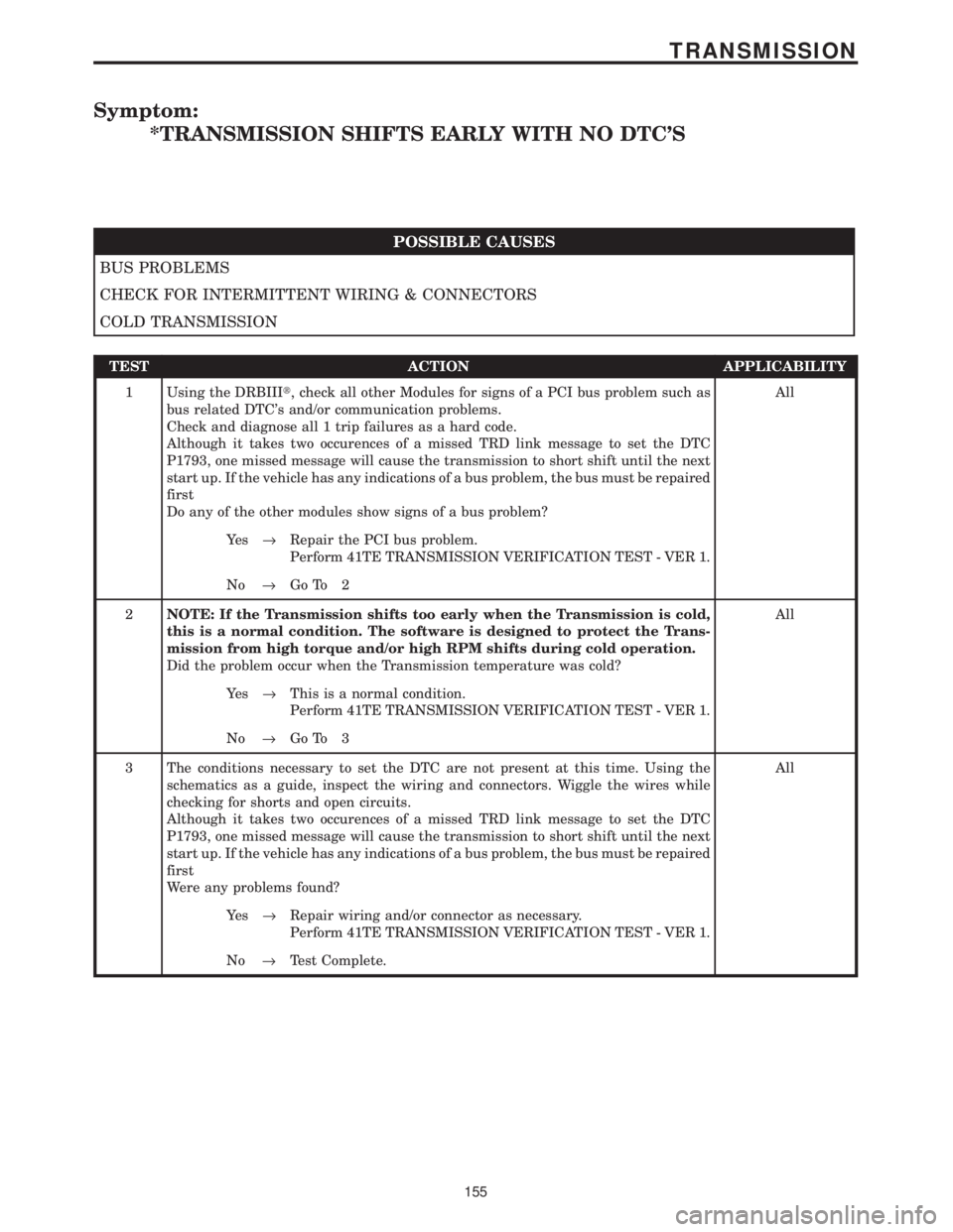
Symptom:
*TRANSMISSION SHIFTS EARLY WITH NO DTC'S
POSSIBLE CAUSES
BUS PROBLEMS
CHECK FOR INTERMITTENT WIRING & CONNECTORS
COLD TRANSMISSION
TEST ACTION APPLICABILITY
1 Using the DRBIIIt, check all other Modules for signs of a PCI bus problem such as
bus related DTC's and/or communication problems.
Check and diagnose all 1 trip failures as a hard code.
Although it takes two occurences of a missed TRD link message to set the DTC
P1793, one missed message will cause the transmission to short shift until the next
start up. If the vehicle has any indications of a bus problem, the bus must be repaired
first
Do any of the other modules show signs of a bus problem?All
Ye s®Repair the PCI bus problem.
Perform 41TE TRANSMISSION VERIFICATION TEST - VER 1.
No®Go To 2
2NOTE: If the Transmission shifts too early when the Transmission is cold,
this is a normal condition. The software is designed to protect the Trans-
mission from high torque and/or high RPM shifts during cold operation.
Did the problem occur when the Transmission temperature was cold?All
Ye s®This is a normal condition.
Perform 41TE TRANSMISSION VERIFICATION TEST - VER 1.
No®Go To 3
3 The conditions necessary to set the DTC are not present at this time. Using the
schematics as a guide, inspect the wiring and connectors. Wiggle the wires while
checking for shorts and open circuits.
Although it takes two occurences of a missed TRD link message to set the DTC
P1793, one missed message will cause the transmission to short shift until the next
start up. If the vehicle has any indications of a bus problem, the bus must be repaired
first
Were any problems found?All
Ye s®Repair wiring and/or connector as necessary.
Perform 41TE TRANSMISSION VERIFICATION TEST - VER 1.
No®Test Complete.
155
TRANSMISSION
Page 4261 of 4284

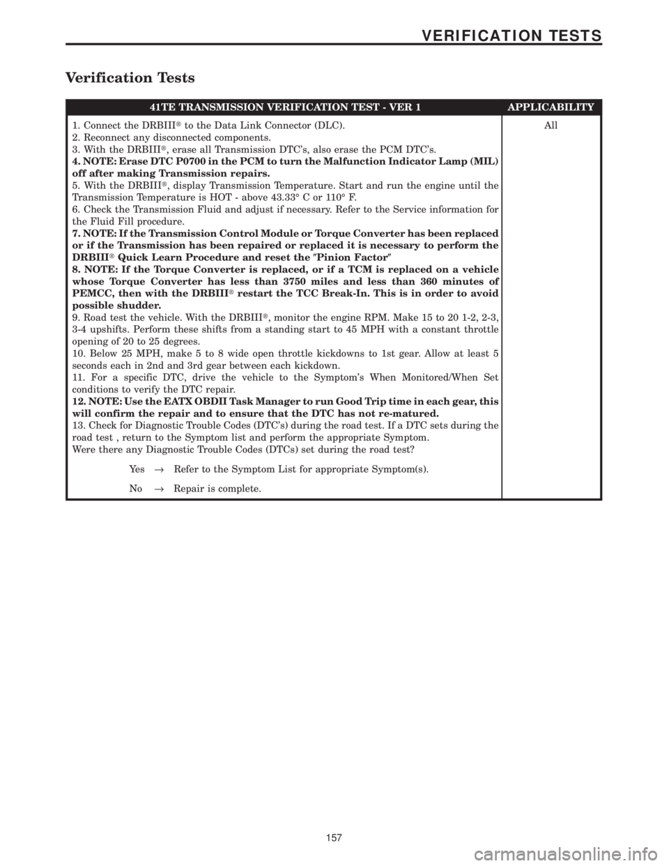
Verification Tests
41TE TRANSMISSION VERIFICATION TEST - VER 1 APPLICABILITY
1. Connect the DRBIIItto the Data Link Connector (DLC).
2. Reconnect any disconnected components.
3. With the DRBIIIt, erase all Transmission DTC's, also erase the PCM DTC's.
4. NOTE: Erase DTC P0700 in the PCM to turn the Malfunction Indicator Lamp (MIL)
off after making Transmission repairs.
5. With the DRBIIIt, display Transmission Temperature. Start and run the engine until the
Transmission Temperature is HOT - above 43.33É C or 110É F.
6. Check the Transmission Fluid and adjust if necessary. Refer to the Service information for
the Fluid Fill procedure.
7. NOTE: If the Transmission Control Module or Torque Converter has been replaced
or if the Transmission has been repaired or replaced it is necessary to perform the
DRBIIItQuick Learn Procedure and reset the(Pinion Factor(
8. NOTE: If the Torque Converter is replaced, or if a TCM is replaced on a vehicle
whose Torque Converter has less than 3750 miles and less than 360 minutes of
PEMCC, then with the DRBIIItrestart the TCC Break-In. This is in order to avoid
possible shudder.
9. Road test the vehicle. With the DRBIIIt, monitor the engine RPM. Make 15 to 20 1-2, 2-3,
3-4 upshifts. Perform these shifts from a standing start to 45 MPH with a constant throttle
opening of 20 to 25 degrees.
10. Below 25 MPH, make 5 to 8 wide open throttle kickdowns to 1st gear. Allow at least 5
seconds each in 2nd and 3rd gear between each kickdown.
11. For a specific DTC, drive the vehicle to the Symptom's When Monitored/When Set
conditions to verify the DTC repair.
12. NOTE: Use the EATX OBDII Task Manager to run Good Trip time in each gear, this
will confirm the repair and to ensure that the DTC has not re-matured.
13. Check for Diagnostic Trouble Codes (DTC's) during the road test. If a DTC sets during the
road test , return to the Symptom list and perform the appropriate Symptom.
Were there any Diagnostic Trouble Codes (DTCs) set during the road test?All
Ye s®Refer to the Symptom List for appropriate Symptom(s).
No®Repair is complete.
157
VERIFICATION TESTS
Page 4276 of 4284

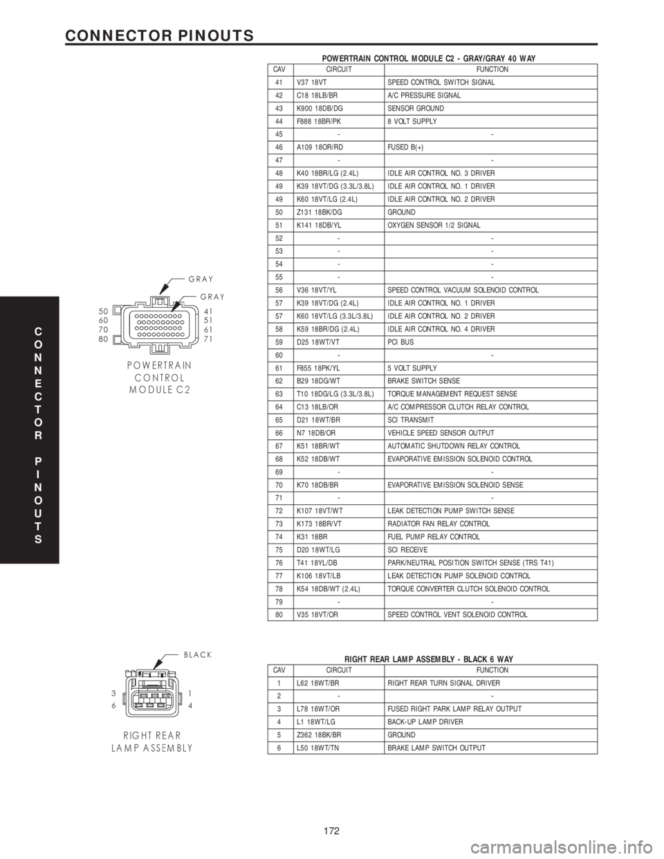
POWERTRAIN CONTROL MODULE C2 - GRAY/GRAY 40 WAYCAV CIRCUIT FUNCTION
41 V37 18VT SPEED CONTROL SWITCH SIGNAL
42 C18 18LB/BR A/C PRESSURE SIGNAL
43 K900 18DB/DG SENSOR GROUND
44 F888 18BR/PK 8 VOLT SUPPLY
45 - -
46 A109 18OR/RD FUSED B(+)
47 - -
48 K40 18BR/LG (2.4L) IDLE AIR CONTROL NO. 3 DRIVER
49 K39 18VT/DG (3.3L/3.8L) IDLE AIR CONTROL NO. 1 DRIVER
49 K60 18VT/LG (2.4L) IDLE AIR CONTROL NO. 2 DRIVER
50 Z131 18BK/DG GROUND
51 K141 18DB/YL OXYGEN SENSOR 1/2 SIGNAL
52 - -
53 - -
54 - -
55 - -
56 V36 18VT/YL SPEED CONTROL VACUUM SOLENOID CONTROL
57 K39 18VT/DG (2.4L) IDLE AIR CONTROL NO. 1 DRIVER
57 K60 18VT/LG (3.3L/3.8L) IDLE AIR CONTROL NO. 2 DRIVER
58 K59 18BR/DG (2.4L) IDLE AIR CONTROL NO. 4 DRIVER
59 D25 18WT/VT PCI BUS
60 - -
61 F855 18PK/YL 5 VOLT SUPPLY
62 B29 18DG/WT BRAKE SWITCH SENSE
63 T10 18DG/LG (3.3L/3.8L) TORQUE MANAGEMENT REQUEST SENSE
64 C13 18LB/OR A/C COMPRESSOR CLUTCH RELAY CONTROL
65 D21 18WT/BR SCI TRANSMIT
66 N7 18DB/OR VEHICLE SPEED SENSOR OUTPUT
67 K51 18BR/WT AUTOMATIC SHUTDOWN RELAY CONTROL
68 K52 18DB/WT EVAPORATIVE EMISSION SOLENOID CONTROL
69 - -
70 K70 18DB/BR EVAPORATIVE EMISSION SOLENOID SENSE
71 - -
72 K107 18VT/WT LEAK DETECTION PUMP SWITCH SENSE
73 K173 18BR/VT RADIATOR FAN RELAY CONTROL
74 K31 18BR FUEL PUMP RELAY CONTROL
75 D20 18WT/LG SCI RECEIVE
76 T41 18YL/DB PARK/NEUTRAL POSITION SWITCH SENSE (TRS T41)
77 K106 18VT/LB LEAK DETECTION PUMP SOLENOID CONTROL
78 K54 18DB/WT (2.4L) TORQUE CONVERTER CLUTCH SOLENOID CONTROL
79 - -
80 V35 18VT/OR SPEED CONTROL VENT SOLENOID CONTROL
RIGHT REAR LAMP ASSEMBLY - BLACK 6 WAYCAV CIRCUIT FUNCTION
1 L62 18WT/BR RIGHT REAR TURN SIGNAL DRIVER
2- -
3 L78 18WT/OR FUSED RIGHT PARK LAMP RELAY OUTPUT
4 L1 18WT/LG BACK-UP LAMP DRIVER
5 Z362 18BK/BR GROUND
6 L50 18WT/TN BRAKE LAMP SWITCH OUTPUT
C
O
N
N
E
C
T
O
R
P
I
N
O
U
T
S
172
CONNECTOR PINOUTS
Page 4277 of 4284
SOLENOID/PRESSURE SWITCH ASSEMBLY (3.3L/3.8L) - BLACK 8 WAYCAV CIRCUIT FUNCTION
1 T47 18YL/DG 2-4 PRESSURE SWITCH SENSE
2 T50 18YL/TN LOW/REVERSE PRESSURE SWITCH SENSE
3 T9 18DG/TN OVERDRIVE PRESSURE SWITCH SENSE
4 T16 18YL/OR TRANSMISSION SAFETY SHUTDOWN RELAY OUTPUT
5 T59 18YL/LB UNDERDRIVE SOLENOID CONTROL
6 T60 18YL/GY OVERDRIVE SOLENOID CONTROL
7 T20 18DG/WT LOW/REVERSE SOLENOID CONTROL
8 T19 18YL/DB 2-4 SOLENOID CONTROL
THROTTLE POSITION SENSOR - GRAY 3 WAYCAV CIRCUIT FUNCTION
1 K900 18DB/DG SENSOR GROUND
2 K22 18BR/OR THROTTLE POSITION SENSOR SIGNAL
3 F855 18PK/YL 5 VOLT SUPPLY
TORQUE CONVERTER CLUTCH SOLENOID (2.4L) - BLACK 3 WAYCAV CIRCUIT FUNCTION
1- -
2 F202 18PK/GY FUSED IGNITION SWITCH OUTPUT (RUN-START)
3 K54 18DB/WT TORQUE CONVERTER CLUTCH SOLENOID CONTROL
C
O
N
N
E
C
T
O
R
P
I
N
O
U
T
S
173
CONNECTOR PINOUTS
Page 4278 of 4284

TRANSMISSION CONTROL MODULE (3.3L/3.8L) - BLACK 60 WAYCAV CIRCUIT FUNCTION
1 T1 18DG/LB TRS T1 SENSE
2- -
3 T3 18DG/DB TRS T3 SENSE
4- -
5- -
6 K24 18BR/LB CRANKSHAFT POSITION SENSOR SIGNAL
7 D21 18WT/BR SCI TRANSMIT
8 T751 18YL IGNITION SWITCH OUTPUT (START)
9 T9 18DG/TN OVERDRIVE PRESSURE SWITCH SENSE
10 T10 18DG/LG TORQUE MANAGEMENT REQUEST SENSE
11 F1 18PK/WT FCM OUTPUT (UNLOCK-RUN-START)
12 K22 18BR/OR THROTTLE POSITION SENSOR SIGNAL
13 T13 18DG/VT SPEED SENSOR GROUND
14 T14 18DG/BR OUTPUT SPEED SENSOR SIGNAL
15 T15 18YL/BR TRANSMISSION SAFETY SHUTDOWN RELAY CONTROL
16 T16 18YL/OR TRANSMISSION SAFETY SHUTDOWN RELAY OUTPUT
17 T16 18YL/OR TRANSMISSION SAFETY SHUTDOWN RELAY OUTPUT
18 - -
19 T19 18YL/DB 2-4 SOLENOID CONTROL
20 T20 18DG/WT LOW/REVERSE SOLENOID CONTROL
21 - -
22 - -
23 - -
24 - -
25 - -
26 - -
27 - -
28 - -
29 - -
30 - -
31 - -
32 - -
33 - -
34 - -
35 - -
36 - -
37 - -
38 - -
39 - -
40 - -
41 T41 18DG/GY TRS T41 SENSE
42 T42 18DG/YL TRS T42 SENSE
43 D25 18WT/VT PCI BUS
44 - -
45 - -
46 D16 18WT/OR SCI RECEIVE
47 T47 18YL/DG 2-4 PRESSURE SWITCH SENSE
48 - -
49 - -
50 T50 18YL/TN LOW/REVERSE PRESSURE SWITCH SENSE
51 K900 18DB/DG SENSOR GROUND
52 T52 18DG/WT INPUT SPEED SENSOR SIGNAL
53 Z132 16BK/YL GROUND
54 T54 18DG/OR TRANSMISSION TEMPERATURE SENSOR SIGNAL
55 T55 18YL/VT (AUTOSTICK) AUTOSTICK/OVERDRIVE OFF MUX INPUT
56 A104 18YL/RD FUSED B(+)
57 Z133 16BK/LG GROUND
58 N7 18DB/OR VEHICLE SPEED SENSOR SIGNAL
59 T59 18YL/LB UNDERDRIVE SOLENOID CONTROL
60 T60 18YL/GY OVERDRIVE SOLENOID CONTROL
C
O
N
N
E
C
T
O
R
P
I
N
O
U
T
S
174
CONNECTOR PINOUTS