2001 CHRYSLER VOYAGER torque
[x] Cancel search: torquePage 3962 of 4284
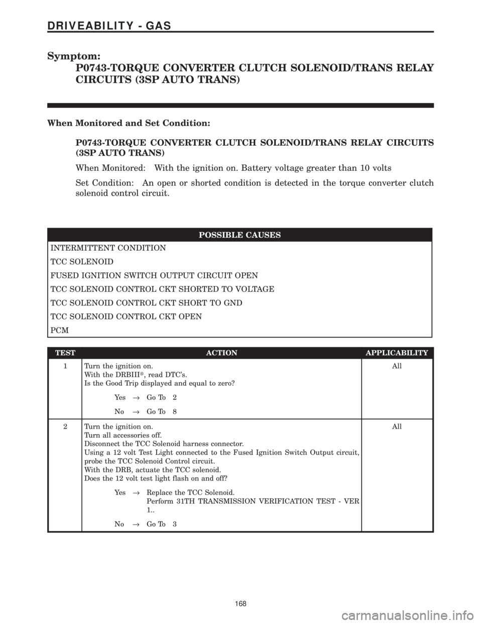
Symptom:
P0743-TORQUE CONVERTER CLUTCH SOLENOID/TRANS RELAY
CIRCUITS (3SP AUTO TRANS)
When Monitored and Set Condition:
P0743-TORQUE CONVERTER CLUTCH SOLENOID/TRANS RELAY CIRCUITS
(3SP AUTO TRANS)
When Monitored: With the ignition on. Battery voltage greater than 10 volts
Set Condition: An open or shorted condition is detected in the torque converter clutch
solenoid control circuit.
POSSIBLE CAUSES
INTERMITTENT CONDITION
TCC SOLENOID
FUSED IGNITION SWITCH OUTPUT CIRCUIT OPEN
TCC SOLENOID CONTROL CKT SHORTED TO VOLTAGE
TCC SOLENOID CONTROL CKT SHORT TO GND
TCC SOLENOID CONTROL CKT OPEN
PCM
TEST ACTION APPLICABILITY
1 Turn the ignition on.
With the DRBIIIt, read DTC's.
Is the Good Trip displayed and equal to zero?All
Ye s®Go To 2
No®Go To 8
2 Turn the ignition on.
Turn all accessories off.
Disconnect the TCC Solenoid harness connector.
Using a 12 volt Test Light connected to the Fused Ignition Switch Output circuit,
probe the TCC Solenoid Control circuit.
With the DRB, actuate the TCC solenoid.
Does the 12 volt test light flash on and off?All
Ye s®Replace the TCC Solenoid.
Perform 31TH TRANSMISSION VERIFICATION TEST - VER
1..
No®Go To 3
168
DRIVEABILITY - GAS
Page 3963 of 4284
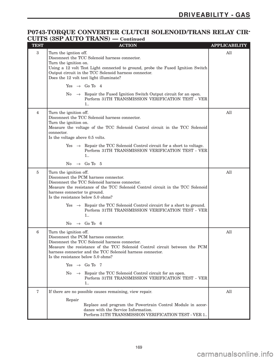
TEST ACTION APPLICABILITY
3 Turn the igntion off.
Disconnect the TCC Solenoid harness connector.
Turn the ignition on.
Using a 12 volt Test Light connected to ground, probe the Fused Ignition Switch
Output circuit in the TCC Solenoid harness connector.
Does the 12 volt test light illuminate?All
Ye s®Go To 4
No®Repair the Fused Ignition Switch Output circuit for an open.
Perform 31TH TRANSMISSION VERIFICATION TEST - VER
1..
4 Turn the ignition off.
Disconnect the TCC Solenoid harness connector.
Turn the ignition on.
Measure the voltage of the TCC Solenoid Control circuit in the TCC Solenoid
connector.
Is the voltage above 0.5 volts.All
Ye s®Repair the TCC Solenoid Control circuit for a short to voltage.
Perform 31TH TRANSMISSION VERIFICATION TEST - VER
1..
No®Go To 5
5 Turn the ignition off.
Disconnect the PCM harness connector.
Disconnect the TCC Solenoid harness connector.
Measure the resistance of the TCC Solenoid Control circuit in the TCC Solenoid
harness connector to ground.
Is the resistance below 5.0 ohms?All
Ye s®Repair the TCC Solenoid Control circuirt for a short to ground.
Perform 31TH TRANSMISSION VERIFICATION TEST - VER
1..
No®Go To 6
6 Turn the ignition off.
Disconnect the PCM harness connector.
Disconnect the TCC Solenoid harness connector.
Measure the resistance of the TCC Solenoid Control circuit between the PCM
harness connector and the TCC Solenoid harness connector.
Is the resistance below 5.0 ohms?All
Ye s®Go To 7
No®Repair the TCC Solenoid Control circuit for an open.
Perform 31TH TRANSMISSION VERIFICATION TEST - VER
1..
7 If there are no possible causes remaining, view repair. All
Repair
Replace and program the Powertrain Control Module in accor-
dance with the Service Information.
Perform 31TH TRANSMISSION VERIFICATION TEST - VER 1..
169
DRIVEABILITY - GAS
P0743-TORQUE CONVERTER CLUTCH SOLENOID/TRANS RELAY CIR-
CUITS (3SP AUTO TRANS) Ð
Continued
Page 3964 of 4284
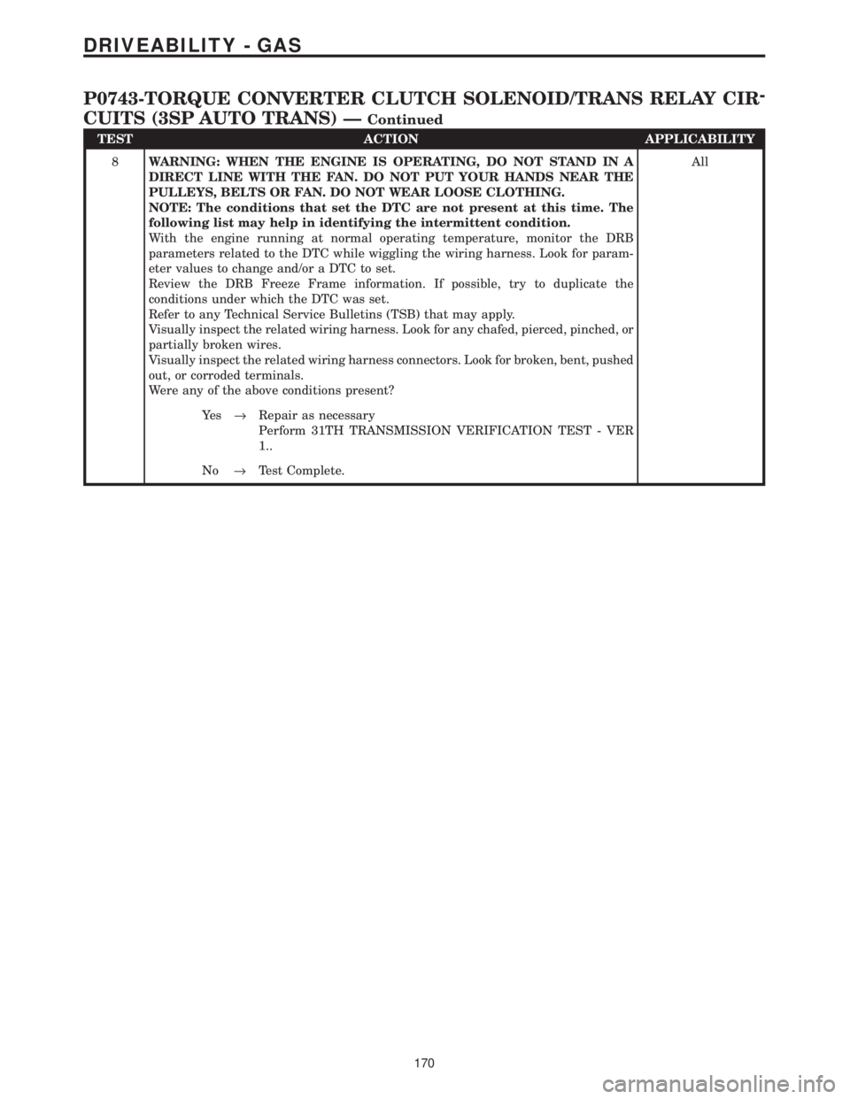
TEST ACTION APPLICABILITY
8WARNING: WHEN THE ENGINE IS OPERATING, DO NOT STAND IN A
DIRECT LINE WITH THE FAN. DO NOT PUT YOUR HANDS NEAR THE
PULLEYS, BELTS OR FAN. DO NOT WEAR LOOSE CLOTHING.
NOTE: The conditions that set the DTC are not present at this time. The
following list may help in identifying the intermittent condition.
With the engine running at normal operating temperature, monitor the DRB
parameters related to the DTC while wiggling the wiring harness. Look for param-
eter values to change and/or a DTC to set.
Review the DRB Freeze Frame information. If possible, try to duplicate the
conditions under which the DTC was set.
Refer to any Technical Service Bulletins (TSB) that may apply.
Visually inspect the related wiring harness. Look for any chafed, pierced, pinched, or
partially broken wires.
Visually inspect the related wiring harness connectors. Look for broken, bent, pushed
out, or corroded terminals.
Were any of the above conditions present?All
Ye s®Repair as necessary
Perform 31TH TRANSMISSION VERIFICATION TEST - VER
1..
No®Test Complete.
170
DRIVEABILITY - GAS
P0743-TORQUE CONVERTER CLUTCH SOLENOID/TRANS RELAY CIR-
CUITS (3SP AUTO TRANS) Ð
Continued
Page 4069 of 4284
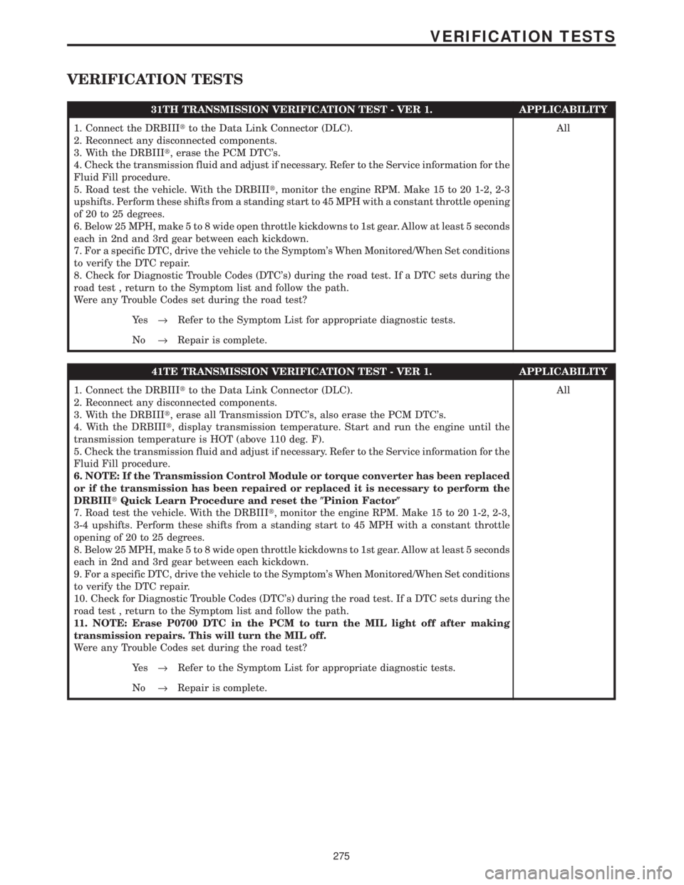
VERIFICATION TESTS
31TH TRANSMISSION VERIFICATION TEST - VER 1. APPLICABILITY
1. Connect the DRBIIItto the Data Link Connector (DLC).
2. Reconnect any disconnected components.
3. With the DRBIIIt, erase the PCM DTC's.
4. Check the transmission fluid and adjust if necessary. Refer to the Service information for the
Fluid Fill procedure.
5. Road test the vehicle. With the DRBIIIt, monitor the engine RPM. Make 15 to 20 1-2, 2-3
upshifts. Perform these shifts from a standing start to 45 MPH with a constant throttle opening
of 20 to 25 degrees.
6. Below 25 MPH, make 5 to 8 wide open throttle kickdowns to 1st gear. Allow at least 5 seconds
each in 2nd and 3rd gear between each kickdown.
7. For a specific DTC, drive the vehicle to the Symptom's When Monitored/When Set conditions
to verify the DTC repair.
8. Check for Diagnostic Trouble Codes (DTC's) during the road test. If a DTC sets during the
road test , return to the Symptom list and follow the path.
Were any Trouble Codes set during the road test?All
Ye s®Refer to the Symptom List for appropriate diagnostic tests.
No®Repair is complete.
41TE TRANSMISSION VERIFICATION TEST - VER 1. APPLICABILITY
1. Connect the DRBIIItto the Data Link Connector (DLC).
2. Reconnect any disconnected components.
3. With the DRBIIIt, erase all Transmission DTC's, also erase the PCM DTC's.
4. With the DRBIIIt, display transmission temperature. Start and run the engine until the
transmission temperature is HOT (above 110 deg. F).
5. Check the transmission fluid and adjust if necessary. Refer to the Service information for the
Fluid Fill procedure.
6. NOTE: If the Transmission Control Module or torque converter has been replaced
or if the transmission has been repaired or replaced it is necessary to perform the
DRBIIItQuick Learn Procedure and reset the(Pinion Factor(
7. Road test the vehicle. With the DRBIIIt, monitor the engine RPM. Make 15 to 20 1-2, 2-3,
3-4 upshifts. Perform these shifts from a standing start to 45 MPH with a constant throttle
opening of 20 to 25 degrees.
8. Below 25 MPH, make 5 to 8 wide open throttle kickdowns to 1st gear. Allow at least 5 seconds
each in 2nd and 3rd gear between each kickdown.
9. For a specific DTC, drive the vehicle to the Symptom's When Monitored/When Set conditions
to verify the DTC repair.
10. Check for Diagnostic Trouble Codes (DTC's) during the road test. If a DTC sets during the
road test , return to the Symptom list and follow the path.
11. NOTE: Erase P0700 DTC in the PCM to turn the MIL light off after making
transmission repairs. This will turn the MIL off.
Were any Trouble Codes set during the road test?All
Ye s®Refer to the Symptom List for appropriate diagnostic tests.
No®Repair is complete.
275
VERIFICATION TESTS
Page 4096 of 4284
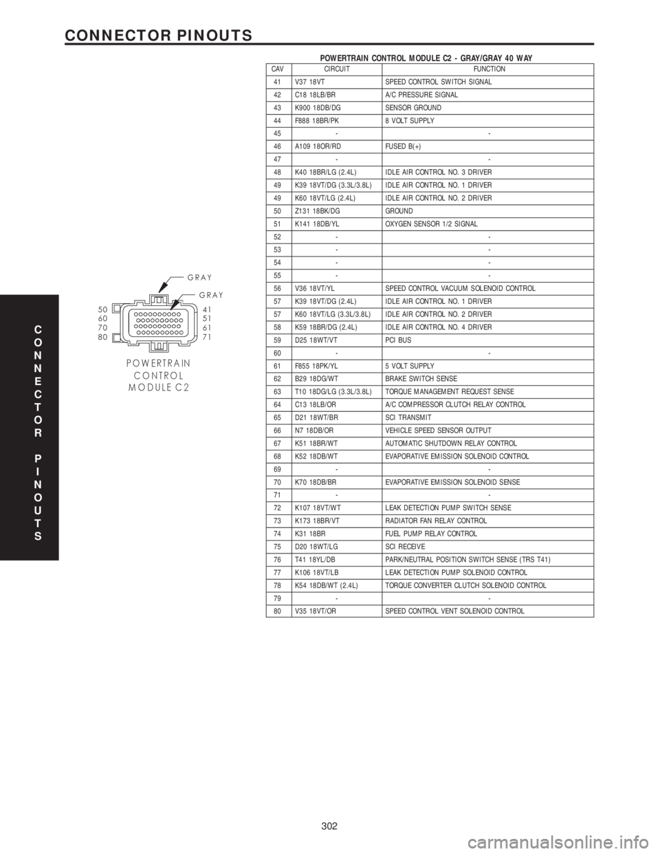
POWERTRAIN CONTROL MODULE C2 - GRAY/GRAY 40 WAYCAV CIRCUIT FUNCTION
41 V37 18VT SPEED CONTROL SWITCH SIGNAL
42 C18 18LB/BR A/C PRESSURE SIGNAL
43 K900 18DB/DG SENSOR GROUND
44 F888 18BR/PK 8 VOLT SUPPLY
45 - -
46 A109 18OR/RD FUSED B(+)
47 - -
48 K40 18BR/LG (2.4L) IDLE AIR CONTROL NO. 3 DRIVER
49 K39 18VT/DG (3.3L/3.8L) IDLE AIR CONTROL NO. 1 DRIVER
49 K60 18VT/LG (2.4L) IDLE AIR CONTROL NO. 2 DRIVER
50 Z131 18BK/DG GROUND
51 K141 18DB/YL OXYGEN SENSOR 1/2 SIGNAL
52 - -
53 - -
54 - -
55 - -
56 V36 18VT/YL SPEED CONTROL VACUUM SOLENOID CONTROL
57 K39 18VT/DG (2.4L) IDLE AIR CONTROL NO. 1 DRIVER
57 K60 18VT/LG (3.3L/3.8L) IDLE AIR CONTROL NO. 2 DRIVER
58 K59 18BR/DG (2.4L) IDLE AIR CONTROL NO. 4 DRIVER
59 D25 18WT/VT PCI BUS
60 - -
61 F855 18PK/YL 5 VOLT SUPPLY
62 B29 18DG/WT BRAKE SWITCH SENSE
63 T10 18DG/LG (3.3L/3.8L) TORQUE MANAGEMENT REQUEST SENSE
64 C13 18LB/OR A/C COMPRESSOR CLUTCH RELAY CONTROL
65 D21 18WT/BR SCI TRANSMIT
66 N7 18DB/OR VEHICLE SPEED SENSOR OUTPUT
67 K51 18BR/WT AUTOMATIC SHUTDOWN RELAY CONTROL
68 K52 18DB/WT EVAPORATIVE EMISSION SOLENOID CONTROL
69 - -
70 K70 18DB/BR EVAPORATIVE EMISSION SOLENOID SENSE
71 - -
72 K107 18VT/WT LEAK DETECTION PUMP SWITCH SENSE
73 K173 18BR/VT RADIATOR FAN RELAY CONTROL
74 K31 18BR FUEL PUMP RELAY CONTROL
75 D20 18WT/LG SCI RECEIVE
76 T41 18YL/DB PARK/NEUTRAL POSITION SWITCH SENSE (TRS T41)
77 K106 18VT/LB LEAK DETECTION PUMP SOLENOID CONTROL
78 K54 18DB/WT (2.4L) TORQUE CONVERTER CLUTCH SOLENOID CONTROL
79 - -
80 V35 18VT/OR SPEED CONTROL VENT SOLENOID CONTROL
C
O
N
N
E
C
T
O
R
P
I
N
O
U
T
S
302
CONNECTOR PINOUTS
Page 4102 of 4284

TABLE OF CONTENTS - Continued
TRANSMISSION
P0120-THROTTLE POSITION SENSOR SIGNAL CIRCUIT.....................24
P0600-SERIAL COMMUNICATION LINK MALFUNCTION.......................26
P0604-INTERNAL TCM..................................................28
P0605-INTERNAL TCM..................................................29
P0700-INTERNAL TCM..................................................30
P0705-CHECK SHIFTER SIGNAL..........................................31
P0715-INPUT SPEED SENSOR ERROR....................................38
P0720-OUTPUT SPEED SENSOR ERROR..................................42
P0725-ENGINE SPEED SENSOR CIRCUIT (3.3L/3.8L)........................46
P0725-ENGINE SPEED SENSOR CIRCUIT (3.5L)............................48
P0731-GEAR RATIO ERROR IN 1ST.......................................51
P0732-GEAR RATIO ERROR IN 2ND.......................................53
P0733-GEAR RATIO ERROR IN 3RD.......................................55
P0734-GEAR RATIO ERROR IN 4TH.......................................57
P0736-GEAR RATIO ERROR IN REVERSE..................................59
P0740-TORQUE CONVERTER CLUTCH CONTROL CIRCUIT...................61
P0750-LR SOLENOID CIRCUIT............................................63
P0755-2-4 SOLENOID CIRCUIT...........................................66
P0760-OD SOLENOID CIRCUIT...........................................69
P0765-UD SOLENOID CIRCUIT...........................................72
P1714-LOW BATTERY VOLTAGE..........................................75
P1716-BUS COMMUNICATION WITH PCM..................................79
P1717-NO COMMUNICATION WITH THE MIC...............................81
P1738-HIGH TEMPERATURE OPERATION ACTIVATED.......................83
P1739-POWER UP AT SPEED............................................85
P1765-SWITCHED BATTERY.............................................86
P1767-TRANSMISSION RELAY ALWAYS ON................................89
P1768-RELAY OUTPUT ALWAYS OFF......................................92
P1775-SOLENOID SWITCH VALVE LATCHED IN TCC POSITION...............96
P1776-SOLENOID SWITCH VALVE LATCHED IN LR POSITION................100
P1781-OD PRESSURE SWITCH SENSE CIRCUIT...........................104
P1782 - 2-4 PRESSURE SWITCH SENSE CIRCUIT..........................107
P1784-LR PRESSURE SWITCH SENSE CIRCUIT...........................110
P1787-OD HYDRAULIC PRESSURE TEST FAILURE.........................114
P1788-2/4 HYDRAULIC PRESSURE TEST FAILURE.........................118
P1789-2-4/OD HYDRAULIC PRESSURE TEST FAILURE......................122
P1790-FAULT IMMEDIATELY AFTER SHIFT................................123
P1791-LOSS OF PRIME.................................................124
P1792-BATTERY WAS DISCONNECTED...................................127
P1793-TRD LINK COMMUNICATION ERROR...............................130
P1794-SPEED SENSOR GROUND ERROR................................133
P1795-INTERNAL TCM.................................................135
P1796-AUTOSTICK SENSOR CIRCUIT....................................136
P1797-MANUAL SHIFT OVERHEAT.......................................139
P1798-WORN OUT/BURNT TRANSAXLE FLUID.............................140
P1799-CALCULATED OIL TEMP IN USE...................................142
*BRAKE SHIFT INTERLOCK OUTPUT OPEN...............................146
*CHECKING PARK/NEUTRAL SWITCH OPERATION.........................148
*INCORRECT TRANSMISSION FLUID LEVEL...............................150
*NO BACK UP LAMP OPERATION........................................151
*NO SPEEDOMETER OPERATION........................................153
*TRANSMISSION NOISY WITH NO DTC'S PRESENT........................154
ii
Page 4103 of 4284
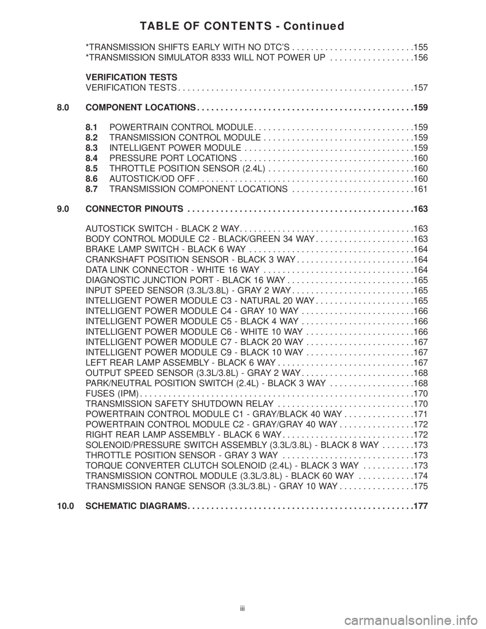
TABLE OF CONTENTS - Continued
*TRANSMISSION SHIFTS EARLY WITH NO DTC'S..........................155
*TRANSMISSION SIMULATOR 8333 WILL NOT POWER UP..................156
VERIFICATION TESTS
VERIFICATION TESTS..................................................157
8.0 COMPONENT LOCATIONS..............................................159
8.1POWERTRAIN CONTROL MODULE..................................159
8.2TRANSMISSION CONTROL MODULE................................159
8.3INTELLIGENT POWER MODULE....................................159
8.4PRESSURE PORT LOCATIONS.....................................160
8.5THROTTLE POSITION SENSOR (2.4L)...............................160
8.6AUTOSTICK/OD OFF..............................................160
8.7TRANSMISSION COMPONENT LOCATIONS..........................161
9.0 CONNECTOR PINOUTS................................................163
AUTOSTICK SWITCH - BLACK 2 WAY.....................................163
BODY CONTROL MODULE C2 - BLACK/GREEN 34 WAY.....................163
BRAKE LAMP SWITCH - BLACK 6 WAY...................................164
CRANKSHAFT POSITION SENSOR - BLACK 3 WAY.........................164
DATA LINK CONNECTOR - WHITE 16 WAY................................164
DIAGNOSTIC JUNCTION PORT - BLACK 16 WAY...........................165
INPUT SPEED SENSOR (3.3L/3.8L) - GRAY 2 WAY..........................165
INTELLIGENT POWER MODULE C3 - NATURAL 20 WAY.....................165
INTELLIGENT POWER MODULE C4 - GRAY 10 WAY........................166
INTELLIGENT POWER MODULE C5 - BLACK 4 WAY........................166
INTELLIGENT POWER MODULE C6 - WHITE 10 WAY.......................166
INTELLIGENT POWER MODULE C7 - BLACK 20 WAY.......................167
INTELLIGENT POWER MODULE C9 - BLACK 10 WAY.......................167
LEFT REAR LAMP ASSEMBLY - BLACK 6 WAY.............................167
OUTPUT SPEED SENSOR (3.3L/3.8L) - GRAY 2 WAY........................168
PARK/NEUTRAL POSITION SWITCH (2.4L) - BLACK 3 WAY..................168
FUSES (IPM)..........................................................170
TRANSMISSION SAFETY SHUTDOWN RELAY.............................170
POWERTRAIN CONTROL MODULE C1 - GRAY/BLACK 40 WAY...............171
POWERTRAIN CONTROL MODULE C2 - GRAY/GRAY 40 WAY................172
RIGHT REAR LAMP ASSEMBLY - BLACK 6 WAY............................172
SOLENOID/PRESSURE SWITCH ASSEMBLY (3.3L/3.8L) - BLACK 8 WAY.......173
THROTTLE POSITION SENSOR - GRAY 3 WAY............................173
TORQUE CONVERTER CLUTCH SOLENOID (2.4L) - BLACK 3 WAY...........173
TRANSMISSION CONTROL MODULE (3.3L/3.8L) - BLACK 60 WAY............174
TRANSMISSION RANGE SENSOR (3.3L/3.8L) - GRAY 10 WAY................175
10.0 SCHEMATIC DIAGRAMS................................................177
iii
Page 4106 of 4284
3.2.2 TRANSMISSION OPERATION AND
SHIFT SCHEDULING AT VARIOUS
OIL TEMPERATURES.
The transmission covered in this manual has
unique shift schedules depending on the tempera-
ture of the transmission oil. The shift schedule is
modified to extend the life of the transmission while
operating under extreme conditions.
The oil temperature is measured with a Temper-
ature Sensor on the 41TE/AE transmission. The
Temperature Sensor is an integral component of the
Transmission Range Sensor (TRS). If the Tempera-
ture Sensor is faulty, (DTC P1799(74)) the trans-
mission will default to a calculated oil temperature.
Oil temperature will then be calculated through a
complex heat transfer equation which uses engine
coolant temperature, battery/ambient temperature,
and engine off time from the Body Control Module
(BCM). These inputs are received from the PCI bus
periodically and used to initialize the oil tempera-
ture at start up. Once the engine is started, the
TCM updates the transmission oil temperature
based on torque converter slip speed, vehicle speed,
gear, and engine coolant temperature to determine
an estimated oil temperature during vehicle opera-
tion. Vehicles using a calculated oil temperature
track oil temperature reasonably accurate during
normal operation. However, if a transmission is
overfilled, a transmission oil cooler becomes re-
stricted, or if a customer drives aggressively in low
gear, the calculated oil temperature will be inaccu-
rate. Consequently the shift schedule selected may
be inappropriate for the current conditions. The key
highlights of the various shift schedules are as
follows:
Extreme Cold:Oil temperature at start up below
-26.6C (-16ÉF)
> Goes to a Cold schedule above -24C (-12ÉF) oil
temperature
> Park, Reverse, Neutral and 2nd gear only (pre-
vents shifting which may fail a clutch with fre-
quent shifts)
Cold:Oil temperature at start up above -24C
(-12ÉF) and below 2.2C (36ÉF)
> Goes to a Warm schedule above 4.4C (40ÉF) oil
temperature
> Delayed 2-3 upshift approximately 35-50 Km/h
(22-31 MPH)
> Delayed 3-4 upshift 72-85 Km/h (45-53 MPH)
> Early 4-3 coastdown shift approximately 48
Km/h (30 MPH)
> Early 3-2 coastdown shift approximately 27
Km/h (17 MPH)> High speed 4-2, 3-2, 2-1 kickdown shifts are
prevented
> No EMCC
Warm:Oil temperature at start up above 2.2C
(36ÉF) and below 27C (80ÉF)
> Goes to a Hot schedule above 27C (80ÉF) oil
temperature
> Normal operation (upshifts, kickdowns, and
coastdowns)
> No EMCC
Hot:Oil temperature at start up above 27C (80ÉF)
> Goes to a Overheat schedule above 115C (240ÉF)
oil temperature
> Normal operation (upshifts, kickdowns, and
coastdowns)
> Full EMCC, No PEMCC except to engage
FEMCC
(Except at closed throttle at speeds above 113-133
Km/h (70 - 83 MPH)
Overheat:Oil temperature above 115C (240ÉF) or
engine coolant temperature above 118C (244ÉF)
> Goes to a Hot below 110C (230ÉF) oil temperature
or a Super Overheat above 115C (240ÉF) oil
temperature
> Delayed 2-3 upshift 40-51 Km/h (25-32 MPH)
> Delayed 3-4 upshift 66-77 Km/h (41-48 MPH)
> 3rd gear FEMCC from 48-77 Km/h (30-48 MPH)
> 3rd gear PEMCC from 43-50 Km/h (27-31 MPH)
Super Overheat:Oil temperature above 127C
(260ÉF)
> Goes back to a Overheat below 115C (240ÉF) oil
temperature
> All a Overheat shift schedules features apply
> 2nd gear PEMCC above 35 Km/h (22 MPH)
> Above 35 Km/h (22 MPH) the torque converter
will not unlock unless the throttle is closed (i.e. at
80 Km/h (50 MPH) a 4th FEMCC to 3rd FEMCC
shift will be made during a part throttle kick-
down or a 4th FEMCC to 2nd PEMCC shift will
be made at wide open throttle) or if a wide open
throttle 2nd PEMCC to 1 kickdown is made.
Causes for operation in the wrong tempera-
ture shift schedule:
Extreme Cold or Cold shift schedule at start up:
> Temperature Sensor circuit.
Overheat or Super Overheat shift schedule after
extended operation:
> Operation in city traffic or stop and go traffic
> Engine idle speed too high
> Aggressive driving in low gear
2
GENERAL INFORMATION