2001 CHRYSLER VOYAGER tire pressure
[x] Cancel search: tire pressurePage 46 of 4284
± Evap Temp Sensor Shorted
± Evap Temp Sensor Open
± A/C Pressure Too Low
± A/C Pressure Too High
± Invalid Conditions for Cooldown Test, Evap
Temperature Too Low
If a message other than Cooldown Test Passed
occurs, refer to the appropriate symptom for diag-
nosis.
3.9.1.7 ACTIVE AND STORED TROUBLE
CODES
The Automatic Temperature Control (ATC) is
capable of storing Active and Stored trouble codes.
Active codes indicate a current fault in the system.
Stored codes indicate that a problem has occurred
in the system, however is not currently present.
Active codes cannot be erased until the problem
causing the code has been repaired. At this time the
Active code is converted to a Stored code, which can
be erased using the DRBIIIt.
3.9.2 MANUAL TEMPERATURE CONTROL
3.9.2.1 SYSTEM AVAILABILITY
Depending on the model, either a Single-Zone Air
Conditioning System or a Dual-Zone Air Condition-
ing System is currently available in these vehicles.
3.9.2.2 CABIN HEATER
For Vehicles equipped with a diesel engine, a
Cabin Heater is used in conjunction with the HVAC
system. The Cabin Heater is designed to supply the
vehicle's occupants with heat prior to the engine
reaching operating temperature. For additional in-
formation on this system, refer to Cabin Heater
under General Information and Diagnostic Proce-
dures in this manual.
3.9.2.3 ZONE CONTROL ± SINGLE-ZONE
The Single-Zone Air Conditioning System main-
tains incoming air temperature, airflow, fan speed,
and fresh air intake for the entire vehicle from the
instrument panel mounted A/C ± Heater Control
Module. The full range of temperature that the
system can produce in any mode for the entire
vehicle is available by positioning the blend control
to the desired range.
3.9.2.4 ZONE CONTROL ± DUAL-ZONE
The Dual-Zone Air Conditioning System main-
tains incoming air temperature, airflow, fan speed,
and fresh air intake for the entire vehicle from the
instrument panel mounted A/C ± Heater ControlModule. In addition, this system provides com-
pletely independent side-to-side control of incoming
air temperature. The full range of temperature that
the system can produce in any mode is available on
either side of the vehicle by positioning the inde-
pendent driver and passenger blend controls to the
desired range.
3.9.2.5 AIR DISTRIBUTION
The HVAC unit has five fully adjustable instru-
ment panel outlets. Side-window demister outlets
in the instrument panel eliminate door ducts and
door-to-instrument panel seals. A single, central
mounted outlet delivers air for defrosting the wind-
shield. Air exhausters allow air entering at the
front of the vehicle to flow out the back to the rear
occupants. Mid-cabin comfort control directs only
cooling air flow to the intermediate seat occupants
through outlets at the rear of each front door trim
panel. Air is supplied to these outlets from the
instrument panel through ducts in the doors that
use molded seals at the instrument panel to prevent
air leakage. Wide outlets under the front seats with
directional dividers distribute heated air across the
floor to the intermediate seat occupants. Ducts in
the center of the vehicle under the carpet deliver air
from the HVAC unit to these outlets. Models
equipped with Dual-Zone A/C systems also include
a dust and odor air filter installed in the HAVC
housing.
3.9.2.6 DOOR ACTUATORS
The electric door actuators are a two-wire design.
Each door actuator uses a similar connector wired
directly to the A/C ± Heater Control Module. Single-
Zone systems have one blend door actuator, one
mode door actuator, and one recirculation door
actuator. Dual-Zone systems have two blend door
actuators, one mode door actuator, and one recircu-
lation door actuator. All of the door actuators are
accessible from the vehicle's interior.
3.9.2.7 DOOR ACTUATOR CONTROL
The A/C ± Heater Control Module knows the
number of operating actuator revolutions required
for full door travel as well as the number of actuator
commutator pulses per revolution. Using these pa-
rameters, the A/C ± Heater Control Module runs
the actuator for the number of commutator pulses
that correspond to the desired door position. To
maintain accuracy, the system recalibrates itself
periodically at known zero and full travel condi-
tions.
17
GENERAL INFORMATION
Page 1158 of 4284
1.0 INTRODUCTION
The procedures contained in this manual include
all the specifications, instructions, and graphics
needed to diagnose Mark 20 Antilock Braking Sys-
tem (ABS) and Mark 20 Antilock Braking System
with Traction Control. The diagnostics in this man-
ual are based on the failure condition or symptom
being present at time of diagnosis.
Please follow the recommendations below when
choosing your diagnostic path.
1. First make sure the DRBIIItis communicating
with the CAB. If the DRBIIItdisplays a ªNo
Responseº condition, you must diagnose that
first.
2. Read DTC's (diagnostic trouble codes) with the
DRBIIIt.
3. If no DTC's are present, identify the customer
complaint.
4. Once the DTC or customer complaint is identi-
fied, locate the matching test in the Table of
Contents and begin to diagnose the symptom.
All component location views are in Section 8.0.
All connector pinouts are in Section 9.0. All sche-
matics are in Section 10.0.
An * placed before the symptom description indi-
cates a concern with no associated DTC.
When repairs are required, refer to the appropri-
ate service manual for the proper removal and
repair procedure.
Diagnostic procedures change every year. New
diagnostic systems may be added; carry over sys-
tems may be enhanced. READ THIS MANUAL
BEFORE TRYING TO DIAGNOSE A VEHICLE
CODE. It is recommended that you review the
entire manual to become familiar with all new and
changed diagnostic procedures.
After using this book, if you have any comments
or recommendations, please fill out the form at the
back of the book and mail it back to us.
1.1 SYSTEM COVERAGE
This diagnostic procedure manual covers the an-
tilock braking system (ABS) and traction control
system found on: 2001 Chrysler Town and Country,
Dodge Caravan and Grand Caravan.
1.2 SIX-STEP TROUBLESHOOTING
PROCEDURE
Diagnosis of the controller antilock brake module
is done in six basic steps:
²verification of complaint
²verification of any related symptoms
²symptom analysis
²problem isolation
²repair of isolated problem
²verification of proper operation
2.0 IDENTIFICATION OF
SYSTEM
Vehicles equipped with the Teves Mark 20 an-
tilock brake system can be identified by the pres-
ence of the controller antilock brake module located
beneath the master cylinder.
3.0 SYSTEM DESCRIPTION AND
FUNCTIONAL OPERATION
3.1 TEVES MARK 20 SYSTEM
DESCRIPTION
The controller antilock brake module is used to
monitor wheel speeds and to modulate (control)
hydraulic pressure in each brake channel. The
modulated hydraulic pressure is used to prevent
wheel lock-up during braking.
The Teves Mark 20 system uses a diagonal split
hydraulic brake system.
In the standard brake mode
the master cylinder primary circuit supplies pressure
to the right front and left rear wheel brakes, and the
secondary master cylinder circuit supplies pressure
to the left front and right rear wheel brakes.
3.2 TRACTION CONTROL SYSTEM (TCS)
DESCRIPTION
The main purpose of traction control is to reduce
wheel slip and maintain traction at the driven
wheels when road surfaces are slippery. The trac-
tion control system reduces wheel slip by braking
the wheel that is losing traction. The system is
designed to operate at speeds below 56 km/h (35
mph).
The Controller Antilock Brake (CAB) monitors
wheel speeds. If, during acceleration, the module
detects front (drive) wheel slip and the brakes are
not applied, the CAB will enter traction control
mode. Traction control works in the following order
when drive wheel slip is detected.
1. Close the (normally open) isolation valves.
2. Start pump/motor and supply volume/pressure
to front hydraulic circuits (pump runs continu-
ously during traction control).
3. Open and close build and decay valves to main-
tain minimum wheel slip and maximum trac-
tion.
1
GENERAL INFORMATION
Page 1160 of 4284
²three power feeds: valves, pump and microproces-
sor
²brake switch
²traction control switch
The CAB outputs include the following:
²ABS warning indicator actuation
²12 volts power to wheel speed sensors
²eight valves
²ten valves with traction control
²diagnostic communication
²PCI bus communication
²traction control lamp illumination
3.3.3 HYDRAULIC CONTROL UNIT
The hydraulic control unit (HCU) contains the
valve block assembly, two accumulators, and pump/
motor assembly. The HCU is attached to the CAB.
Valve Block Assembly:The valve block assem-
bly contains valves with four inlet valves and four
outlet valves. The inlet valves are spring-loaded in
the open position and the outlet valves are spring
loaded in the closed position. During an antilock
stop, these valves are cycled to maintain the proper
slip ratio for each wheel. If a wheel detects slip, the
inlet valve is closed to prevent and further pressure
increase. Then the outlet valve is opened to release
the pressure to the accumulators until the wheel is
no longer slipping. Once the wheel is no longer
slipping, the outlet valve is closed and the inlet
valve is opened to reapply pressure. If the wheel is
decelerating within its predetermined limits (prop-
er slip ratio), the inlet valve will close to hold the
pressure constant. On vehicles which are equipped
with a traction control system, there are two addi-
tional valves that isolate the master cylinder and
rear wheels. During a traction control event the
brakes are applied to reduce wheel slippage.
Pump Motor Assembly:The pump motor as-
sembly provides the extra amount of fluid needed
during antilock braking. The pump is supplied fluid
that is released to the accumulators when the outlet
valve is opened during an antilock stop. The pump
is also used to drain the accumulator circuits after
the antilock stop is complete. The pump is operated
by an integral electric motor. This DC-type motor is
controlled by the CAB. The CAB may turn on the
pump motor when an antilock stop is detected. The
pump continues to run during the antilock stop and
is turned off after the stop is complete. Under some
conditions, the pump motor will run to drain the
accumulators during the next drive off. The CAB
monitors the pump motor operation internally.
Accumulators:The accumulators provide tem-
porary fluid storage during an antilock stop and are
drained by the pump motor.
3.3.4 SWITCHES/SENSORS
Master Cylinder:The master cylinder is a stan-
dard tandem compensating port design for ABS and
non ABS systems. Traction control vehicles use a
dual center port master cylinder. For proper trac-
tion control operation the standard master cylinder
must not be used.
A fluid level switch is located in the master
cylinder fluid reservoir. The switch closes when a
low fluid level is detected. The fluid level switch
turns on the brake warning indicator by grounding
the indicator circuit. This switch does not disable
the ABS system.
Wheel Speed Sensors and Tone Wheels:One
active wheel speed sensor (WSS) is located at each
wheel and sends a small signal to the control
module (CAB). This signal is generated when a
toothed sensor ring (tone wheel) passes by a station-
ary wheel speed sensor. The CAB converts the
signals into digital signals for each wheel.
Because of internal circuitry, correct wheel speed
sensor function cannot be determined by a continu-
ity or resistance check through the sensor.
The front wheel speed sensor is attached to a boss
in the steering knuckle. The tone wheel is an
integral part of the front axle shaft. The rear speed
sensor is mounted though the bearing cover and the
rear tone wheel is an integral part of the rear
bearing hub. The wheel speed sensor air gap is not
adjustable. Refer to the service manual for wheel
speed sensor air gap and resistance specifications.
The four wheel speed sensors are serviced indi-
vidually. The front tone wheels are serviced as an
assembly with the outer constant velocity (C.V.)
joint housing. The rear tone wheels are serviced as
an assembly.
Correct antilock system operation is dependent
on tone wheel speed signals from the wheel speed
sensors. The vehicle's wheels and tires should all be
the same size and type to generate accurate signals.
In addition, the tires should be inflated to the
recommended pressure for optimum system opera-
tion. Variation in wheel and tire size or significant
variations in inflation pressure can produce inaccu-
rate wheel speed signals; however, the system will
continue to function when using the mini-spare.
3.3.5 SYSTEM INITIALIZATION
System initialization starts when the key is
turned to ªrunº. At this point, the CAB performs a
complete self-check of all electrical components in
the antilock systems.
Between 8-17 km/h (5-10 mph), a dynamic test is
performed. This will momentarily cycle the inlet
and outlet valves, check wheel speed sensor cir-
cuitry, and run the pump motor at 25 km/h (15
mph). The CAB will try to test the pump motor. If
3
GENERAL INFORMATION
Page 1375 of 4284
POSSIBLE CAUSES
INJECTOR COMMON DRIVER CIRCUIT OPEN
INTERMITTENT CONDITION
TEST ACTION APPLICABILITY
1WARNING: THE FUEL INJECTION PUMP SUPPLIES HIGH PRESSURE
FUEL TO EACH INDIVIDUAL INJECTOR THROUGH HIGH-PRESSURE
FUEL LINES. FUEL UNDER HIGH PRESSURE CAN PENETRATE SKIN
AND CAUSE PERSONAL INJURY. WEAR SAFETY GOGGLES AND ADE-
QUATE PROTECTIVE CLOTHING.
Turn the ignition on.
With the DRBIIIt, read the ECM DTCs.
Are there any other DTC's present?All
Ye s®Refer to symptom list for problems related to the DTC other than
P1130.
No®Go To 2
2 Turn the ignition on.
With the DRBIIIt, erase the ECM DTCs.
Test drive the vehicle under various load and speed conditions to attempt to duplicate
the fault.
With the DRBIIIt, read the ECM DTCs.
Does the DRBIIItdisplay this DTC?All
Ye s®Go To 3
No®Go To 7
3 Turn the ignition off.
Inspect the entire fuel system for leakage.
Is there any evidence of leakage?All
Ye s®Repair as necessary in accordance with the Service Information.
No®Go To 4
4 Turn the ignition off.
Disconnect the ECM harness connectors.
Disconnect all of the Fuel Injector harness connectors.
Measure the resistance between ground and each of the Fuel Injector Control
circuits.
Is the resistance below 1000 ohms for any of the measurements?All
Ye s®Repair the appropriate Fuel Injector Control circuit for a short to
ground.
No®Go To 5
5 Turn the ignition off.
Disconnect the ECM harness connectors.
Disconnect all of the Fuel Injector harness connectors.
Measure the resistance of the Common Injector Driver circuit between the ECM
harness connector and each Fuel Injector harness connector.
Is the resistance below 10.0 ohms for each measurement?All
Ye s®Go To 6
No®Repair the Injector Common Driver circuit for an open.
156
DRIVEABILITY - DIESEL
P1130-FUEL RAIL PRESSURE MALFUNCTION LEAKAGE DETECTED Ð
Continued
Page 1495 of 4284
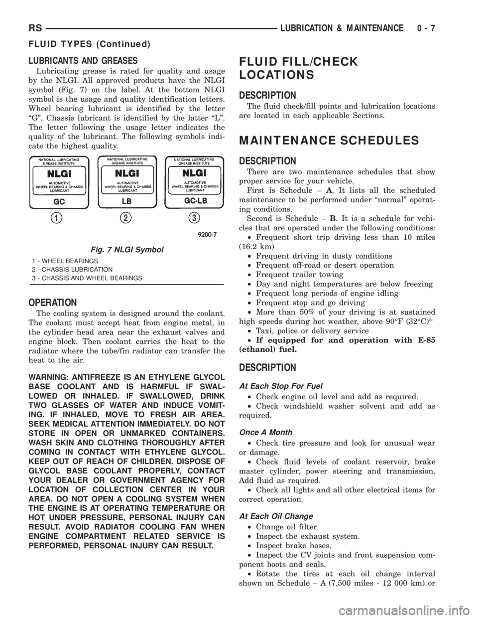
LUBRICANTS AND GREASES
Lubricating grease is rated for quality and usage
by the NLGI. All approved products have the NLGI
symbol (Fig. 7) on the label. At the bottom NLGI
symbol is the usage and quality identification letters.
Wheel bearing lubricant is identified by the letter
ªGº. Chassis lubricant is identified by the latter ªLº.
The letter following the usage letter indicates the
quality of the lubricant. The following symbols indi-
cate the highest quality.
OPERATION
The cooling system is designed around the coolant.
The coolant must accept heat from engine metal, in
the cylinder head area near the exhaust valves and
engine block. Then coolant carries the heat to the
radiator where the tube/fin radiator can transfer the
heat to the air.
WARNING: ANTIFREEZE IS AN ETHYLENE GLYCOL
BASE COOLANT AND IS HARMFUL IF SWAL-
LOWED OR INHALED. IF SWALLOWED, DRINK
TWO GLASSES OF WATER AND INDUCE VOMIT-
ING. IF INHALED, MOVE TO FRESH AIR AREA.
SEEK MEDICAL ATTENTION IMMEDIATELY. DO NOT
STORE IN OPEN OR UNMARKED CONTAINERS.
WASH SKIN AND CLOTHING THOROUGHLY AFTER
COMING IN CONTACT WITH ETHYLENE GLYCOL.
KEEP OUT OF REACH OF CHILDREN. DISPOSE OF
GLYCOL BASE COOLANT PROPERLY, CONTACT
YOUR DEALER OR GOVERNMENT AGENCY FOR
LOCATION OF COLLECTION CENTER IN YOUR
AREA. DO NOT OPEN A COOLING SYSTEM WHEN
THE ENGINE IS AT OPERATING TEMPERATURE OR
HOT UNDER PRESSURE, PERSONAL INJURY CAN
RESULT. AVOID RADIATOR COOLING FAN WHEN
ENGINE COMPARTMENT RELATED SERVICE IS
PERFORMED, PERSONAL INJURY CAN RESULT.
FLUID FILL/CHECK
LOCATIONS
DESCRIPTION
The fluid check/fill points and lubrication locations
are located in each applicable Sections.
MAINTENANCE SCHEDULES
DESCRIPTION
There are two maintenance schedules that show
proper service for your vehicle.
First is Schedule ±A. It lists all the scheduled
maintenance to be performed under ªnormalº operat-
ing conditions.
Second is Schedule ±B. It is a schedule for vehi-
cles that are operated under the following conditions:
²Frequent short trip driving less than 10 miles
(16.2 km)
²Frequent driving in dusty conditions
²Frequent off-road or desert operation
²Frequent trailer towing
²Day and night temperatures are below freezing
²Frequent long periods of engine idling
²Frequent stop and go driving
²More than 50% of your driving is at sustained
high speeds during hot weather, above 90ÉF (32ÉC)*
²Taxi, police or delivery service
²If equipped for and operation with E-85
(ethanol) fuel.
DESCRIPTION
At Each Stop For Fuel
²Check engine oil level and add as required.
²Check windshield washer solvent and add as
required.
Once A Month
²Check tire pressure and look for unusual wear
or damage.
²Check fluid levels of coolant reservoir, brake
master cylinder, power steering and transmission.
Add fluid as required.
²Check all lights and all other electrical items for
correct operation.
At Each Oil Change
²Change oil filter
²Inspect the exhaust system.
²Inspect brake hoses.
²Inspect the CV joints and front suspension com-
ponent boots and seals.
²Rotate the tires at each oil change interval
shown on Schedule ± A (7,500 miles - 12 000 km) or
Fig. 7 NLGI Symbol
1 - WHEEL BEARINGS
2 - CHASSIS LUBRICATION
3 - CHASSIS AND WHEEL BEARINGS
RSLUBRICATION & MAINTENANCE0-7
FLUID TYPES (Continued)
Page 1511 of 4284
FLUID FILL/CHECK
LOCATIONS
DESCRIPTION
The fluid check/fill points and lubrication locations
are located in each applicable service manual section.
MAINTENANCE SCHEDULES
MAINTENANCE SCHEDULES - DIESEL ENGINE
There are two maintenance schedules that show
proper service for the vehicle.
First is ScheduleªAº. It lists all the scheduled
maintenance to be performed under ªnormalº operat-
ing conditions.
Second is ScheduleªBº. It is a schedule for vehi-
cles that are operated under the conditions listed at
the beginning of the schedule.
Use the schedule that best describes the driving
conditions.
Where time and mileage are listed, follow the
interval that occurs first.
At Each Stop for Fuel
²Check the engine oil level, add as required.
²Check the windshield washer solvent and add if
required.
Once a Month
²Check the tire pressure and look for unusual
wear or damage.
²Inspect the battery and clean and tighten termi-
nals as required.
²Check the fluid levels of coolant reservoir, brake
master cylinder, power steering and transaxle and
add as needed.
²Check all lights and all other electrical items for
correct operation.
²Check the rubber seals on each side of the radi-
ator for proper fit.
At Each Oil Change
²Replace the engine oil filter at each oil change.
²Inspect exhaust system.
²Inspect brake hoses
²Inspect the CV joints and front suspension com-
ponents
²Rotate the tires at each oil change interval
shown on schedule ªAº 20 000 km or every other
interval shown on schedule ªBº 20 000 km.
²Check the coolant level, hoses, and clamps.
²Inspect brake linings, hoses and calipers.
²Inspect engine accessory drive belts.
²Inspect for presence of water in fuel filter/water
separator, drain if necessary.
SCHEDULE ªAº
20 000 km (12 000 miles)
²Change engine oil. (1)
²Replace engine oil filter.
²Inspect air filter element. Replace as necessary.
40 000 km (24 000 Miles)
²Change engine oil. (1)
²Replace engine oil filter.
²Replace air filter element.
²Replace fuel filter/water separator element. (2)
²Check alignment.
60 000 km (37 000 Miles)
²Change engine oil. (1)
²Replace engine oil filter.
²Inspect air filter element. Replace as necessary.
80 000 km (49 000 Miles)
²Change engine oil. (1)
²Replace engine oil filter.
²Replace air filter element.
²Replace fuel filter/water separator element. (2)
²Check alignment.
100 000 km (62 000 Miles)
²Change engine oil. (1)
²Replace engine oil filter.
²Inspect air filter element. Replace as necessary.
120 000 km (75 000 Miles)
²Change engine oil. (1)
²Replace engine oil filter.
²Replace air filter element.
²Replace fuel filter/water separator element. (2)
²Check alignment.
140 000 km (86 000 miles)
²Change engine oil. (1)
²Replace engine oil filter.
²Inspect air filter element. Replace as necessary.
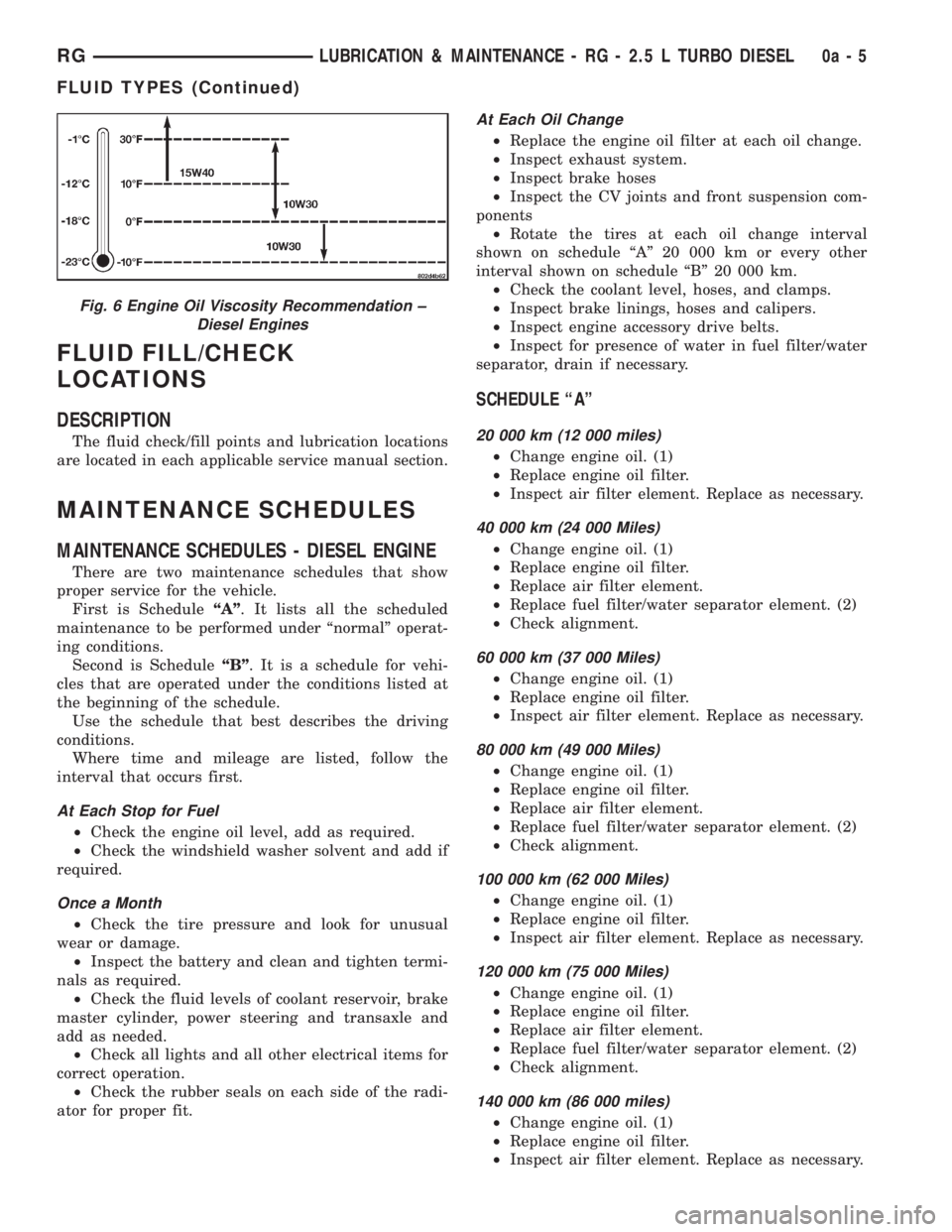
Fig. 6 Engine Oil Viscosity Recommendation ±
Diesel Engines
RGLUBRICATION & MAINTENANCE - RG - 2.5 L TURBO DIESEL0a-5
FLUID TYPES (Continued)
Page 1566 of 4284
CONDITION POSSIBLE CAUSES CORRECTION
7. Loose strut mount to body
attachment7. Tighten strut attachment to specified
torque
8. Loose crossmember bolts 8. Tighten crossmember bolts to
specified torque
Front End Whine With
Vehicle Going Straight At A
Constant Speed1. Defective wheel bearing 1. Replace wheel bearing
2. Incorrect wheel alignment 2. Check and reset wheel alignment
3. Worn tires 3. Replace tires
4. Worn or defective transaxle gears or
bearings4. Replace transaxle gears or bearings
Front End Growl Or
Grinding With Vehicle
Going Straight At A
Constant Speed1. Engine mount grounding 1. Reposition engine as required
2. Worn or broken C/V joint 2. Replace C/V joint
Front End Whine When
Accelerating Or
Decelerating1. Worn or defective transaxle gears or
bearings1. Replace transaxle gears or bearings
Front End Clunk When
Accelerating Or
Decelerating1. Worn or broken engine mount 1. Replace engine mount
2. Worn or defective transaxle gears or
bearings2. Replace transaxle gears or bearings
3. Loose lug nuts 3. Verify wheel lug nut torque
4. Worn or broken C/V joint 4. Replace C/V joint
5. Worn or loose ball joint 5. Tighten or replace ball joint
6. Worn or loose control arm bushing 6. Replace control arm bushing
7. Loose crossmember bolts 7. Tighten crossmember bolts to
specified torque
8. Worn tie rod end 8. Replace tie rod end
Road Wander 1. Incorrect tire pressure 1. Inflate tires to recommended pressure
2. Incorrect front or rear wheel toe 2. Check and reset wheel toe
3. Worn wheel bearings 3. Replace wheel bearing
4. Worn control arm bushings 4. Replace control arm bushing
5. Excessive friction in steering gear 5. Replace steering gear
6. Excessive friction in steering shaft
coupling6. Replace steering coupler
7. Excessive friction in strut upper
bearing7. Replace strut bearing
Lateral Pull 1. Unequal tire pressure 1. Inflate all tires to recommended
pressure
2. Radial tire lead 2. Perform lead correction procedure
3. Incorrect front wheel camber 3. Check and reset front wheel camber
4. Power steering gear imbalance 4. Replace power steering gear
5. Wheel braking 5. Correct braking condition causing
lateral pull
2 - 50 WHEEL ALIGNMENTRS
WHEEL ALIGNMENT (Continued)
Page 1567 of 4284

CONDITION POSSIBLE CAUSES CORRECTION
Excessive Steering Free
Play1. Incorrect Steering Gear Adjustment 1. Adjust Or Replace Steering Gear
2. Worn or loose tie rod ends 2. Replace or tighten tie rod ends
3. Loose steering gear mounting bolts 3. Tighten steering gear bolts to specified
torque
4. Loose or worn steering shaft coupler 4. Replace steering shaft coupler
Excessive Steering Effort 1. Low tire pressure 1. Inflate all tires to recommended
pressure
2. Lack of lubricant in steering gear 2. Replace steering gear
3. Low power steering fluid level 3. Fill power steering fluid reservoir to
correct level
4. Loose power steering pump drive
belt4. Correctly adjust power steering pump
drive belt
5. Lack of lubricant in ball joints 5. Lubricate or replace ball joints
6. Steering gear malfunction 6. Replace steering gear
7. Lack of lubricant in steering coupler 7. Replace steering coupler
STANDARD PROCEDURE - WHEEL ALIGNMENT
PRE-WHEEL ALIGNMENT INSPECTION
Before any attempt is made to change or correct
the wheel alignment, the following inspection and
necessary corrections must be made to ensure proper
alignment.
(1) Verify that the fuel tank is full of fuel. If the
tank is not full, the reduction in weight will affect
the curb height of the vehicle and the alignment
angles.
(2) The passenger and luggage compartments of
the vehicle should be free of any load that is not fac-
tory equipment.
(3) Check the tires on the vehicle. All tires must be
the same size and in good condition with approxi-
mately the same amount of tread wear. Inflate all
the tires to the recommended air pressure.
(4) Check the front wheel and tire assemblies for
excessive radial runout.
(5) Inspect lower ball joints and all steering link-
age for looseness, binding, wear or damage. Repair as
necessary.
(6) Check suspension fasteners for proper torque
and retighten as necessary.
(7) Inspect all suspension component rubber bush-
ings for signs of wear or deterioration. Replace any
faulty bushings or components before aligning the
vehicle.
(8) Check the vehicle's curb height to verify it is
within specifications. Refer to Curb Height Measure-
ment.
WHEEL ALIGNMENT SETUP
(1) Position the vehicle on an alignment rack.
(2) Install all required alignment equipment on
the vehicle per the alignment equipment manufactur-
er's instructions. On this vehicle, a four-wheel align-
ment is recommended.
NOTE: Prior to reading the vehicle's alignment
readouts, the front and rear of vehicle should be
jounced. Induce jounce (rear first, then front) by
grasping the center of the bumper and jouncing
each end of vehicle an equal number of times. The
bumper should always be released when vehicle is
at the bottom of the jounce cycle.
(3) Read the vehicle's current front and rear align-
ment settings. Compare the vehicle's current align-
ment settings to the vehicle specifications for camber,
caster and toe-in. (Refer to 2 - SUSPENSION/
WHEEL ALIGNMENT - SPECIFICATIONS)
(4) If front camber and caster are not within spec-
ifications, proceed to CAMBER AND CASTER below.
If caster and camber are within specifications, pro-
ceed to TOE which can be found following CAMBER
AND CASTER. Rear camber, caster and toe are not
adjustable. If found not to be within specifications,
reinspect for damaged suspension or body compo-
nents and replace as necessary.
CAMBER AND CASTER
Camber and caster settings on this vehicle are
determined at the time the vehicle is designed, by
the location of the vehicle's suspension components.
This is referred to as NET BUILD. The result is no
RSWHEEL ALIGNMENT2-51
WHEEL ALIGNMENT (Continued)