2001 CHRYSLER VOYAGER wheel size
[x] Cancel search: wheel sizePage 31 of 4284
mitted on the bus even though a module may not
require all information to perform its function. It
will only respond to messages ªaddressedº to it
through binary coding process. This method of data
transmission significantly reduces the complexity
of the wiring in the vehicle and the size of wiring
harnesses. All of the information about the func-
tioning of all the systems is organized, controlled,
and communicated by the PCI bus, which is de-
scribed in the Communication Section of this gen-
eral information.
3.1 AIRBAG SYSTEM/OCCUPANT
RESTRAINT CONTROLLER SYSTEM
The 2001 Minivan Airbag System contain the
following components: Occupant Restraint Control-
ler (ORC), Airbag Warning Indicator, Clockspring,
Driver and Passenger Airbags, Seat belt Tensioners
(SBT), Hall-effect Seat Belt Switches (SBS), Left
and Right Side Airbag Control Module (SIACM),
and Seat (mounted side) Airbags.
The Occupant Restraint Controller (ORC) is a
new type of Airbag Control Module (ACM) that
supports staged airbag deployment. Staged deploy-
ment is the ability to trigger airbag system squib
inflators all at once or individually as needed to
provide the appropriate restraint for the severity of
the impact. The ORC has four major functions: PCI
Bus communications, onboard diagnostics, impact
sensing, and component deployment. The ORC also
contains an energy-storage capacitor. This capaci-
tor stores enough electrical energy to deploy the
front airbag components for two seconds following a
battery disconnect or failure during an impact. The
ORC is secured to the floor panel transmission
tunnel below the instrument panel inside the vehi-
cle. The ORC cannot be repaired or adjusted and
must be replaced.
The ORC sends and/or receives PCI Bus mes-
sages with the Instrument Cluster (MIC), Body
Control Module (BCM), and Powertrain Control
Module (PCM). Diagnostic trouble codes will be set
if the communication with these modules is lost or
contains invalid information.
The microprocessor in the ORC monitors the
impact sensor signal and the airbag system electri-
cal circuits to determine the system readiness. The
ORC also monitors bus messages from both SIACM.
If the ORC detects a monitored system fault or
SIACM fault, it sends a message to the instrument
cluster via PCI bus to turn on the airbag warning
indicator. The ORC can set both active and stored
diagnostic trouble codes to aid in the diagnosing
system problems. See ORC/SIACM DIAGNOSTIC
TROUBLE CODES in this section.
The ORC has an internal accelerometer that
senses the rate of vehicle deceleration, which pro-vides verification of the direction and severity of an
impact. A pre-programmed decision algorithm in
the ORC microprocessor determines when the de-
celeration rate is severe enough to require airbag
system protection. The Occupant Restraint Control-
ler (ORC) also uses the driver and front passenger
seat belt switch status (buckled or unbuckled) as
inputs to determine the level of airbag deployment,
low, medium, or high as well as whether or not the
seat belt tensioners should deploy. The ORC also
uses the crash severity to determine the level of
driver and front passenger deployment, low me-
dium or high. When the programmed conditions are
met, the ORC sends an electrical signal to deploy
the appropriate airbag system components.WARNING: THE AIRBAG SYSTEM IS A
SENSITIVE, COMPLEX ELECTRO-
MECHANICAL UNIT. BEFORE ATTEMPTING
TO DIAGNOSE OR SERVICE ANY AIRBAG
SYSTEM OR RELATED STEERING WHEEL,
STEERING COLUMN, OR INSTRUMENT
PANEL COMPONENTS YOU MUST FIRST
DISCONNECT AND ISOLATE THE BATTERY
NEGATIVE (GROUND) CABLE. WAIT TWO
MINUTES FOR THE SYSTEM CAPACITOR TO
DISCHARGE BEFORE FURTHER SYSTEM
SERVICE. THIS IS THE ONLY SURE WAY TO
DISABLE THE AIRBAG SYSTEM. FAILURE
TO DO THIS COULD RESULT IS ACCIDENTAL
AIRBAG DEPLOYMENT AND POSSIBLE
PERSONAL INJURY. NEVER STRIKE OR
KICK THE AIRBAG CONTROL MODULE, AS
IT CAN DAMAGE THE IMPACT SENSOR OR
AFFECT ITS CALIBRATION. IF AN AIRBAG
CONTROL MODULE IS ACCIDENTALLY
DROPPED DURING SERVICE, THE MODULE
MUST BE SCRAPPED AND REPLACED WITH
A NEW UNIT.
The airbag warning lamp is the only point at
which the customer can observe symptoms of a
system malfunction. Whenever the ignition key is
turned to the run or start position, the MIC per-
forms a lamp check by turning the airbag warning
indicator on for 6-8 seconds. After the lamp check, if
the indicator turns on, it means that the ORC has
checked the system and found it to be free of
discernible malfunctions. If the lamp remains on,
there could be an active fault in the system or the
MIC lamp circuit may be internally shorted to
ground. If the lamp comes on and stays on for a
period longer than 6-8 seconds then goes off, there
is usually an intermittent problem in the system.
2
GENERAL INFORMATION
Page 1160 of 4284
²three power feeds: valves, pump and microproces-
sor
²brake switch
²traction control switch
The CAB outputs include the following:
²ABS warning indicator actuation
²12 volts power to wheel speed sensors
²eight valves
²ten valves with traction control
²diagnostic communication
²PCI bus communication
²traction control lamp illumination
3.3.3 HYDRAULIC CONTROL UNIT
The hydraulic control unit (HCU) contains the
valve block assembly, two accumulators, and pump/
motor assembly. The HCU is attached to the CAB.
Valve Block Assembly:The valve block assem-
bly contains valves with four inlet valves and four
outlet valves. The inlet valves are spring-loaded in
the open position and the outlet valves are spring
loaded in the closed position. During an antilock
stop, these valves are cycled to maintain the proper
slip ratio for each wheel. If a wheel detects slip, the
inlet valve is closed to prevent and further pressure
increase. Then the outlet valve is opened to release
the pressure to the accumulators until the wheel is
no longer slipping. Once the wheel is no longer
slipping, the outlet valve is closed and the inlet
valve is opened to reapply pressure. If the wheel is
decelerating within its predetermined limits (prop-
er slip ratio), the inlet valve will close to hold the
pressure constant. On vehicles which are equipped
with a traction control system, there are two addi-
tional valves that isolate the master cylinder and
rear wheels. During a traction control event the
brakes are applied to reduce wheel slippage.
Pump Motor Assembly:The pump motor as-
sembly provides the extra amount of fluid needed
during antilock braking. The pump is supplied fluid
that is released to the accumulators when the outlet
valve is opened during an antilock stop. The pump
is also used to drain the accumulator circuits after
the antilock stop is complete. The pump is operated
by an integral electric motor. This DC-type motor is
controlled by the CAB. The CAB may turn on the
pump motor when an antilock stop is detected. The
pump continues to run during the antilock stop and
is turned off after the stop is complete. Under some
conditions, the pump motor will run to drain the
accumulators during the next drive off. The CAB
monitors the pump motor operation internally.
Accumulators:The accumulators provide tem-
porary fluid storage during an antilock stop and are
drained by the pump motor.
3.3.4 SWITCHES/SENSORS
Master Cylinder:The master cylinder is a stan-
dard tandem compensating port design for ABS and
non ABS systems. Traction control vehicles use a
dual center port master cylinder. For proper trac-
tion control operation the standard master cylinder
must not be used.
A fluid level switch is located in the master
cylinder fluid reservoir. The switch closes when a
low fluid level is detected. The fluid level switch
turns on the brake warning indicator by grounding
the indicator circuit. This switch does not disable
the ABS system.
Wheel Speed Sensors and Tone Wheels:One
active wheel speed sensor (WSS) is located at each
wheel and sends a small signal to the control
module (CAB). This signal is generated when a
toothed sensor ring (tone wheel) passes by a station-
ary wheel speed sensor. The CAB converts the
signals into digital signals for each wheel.
Because of internal circuitry, correct wheel speed
sensor function cannot be determined by a continu-
ity or resistance check through the sensor.
The front wheel speed sensor is attached to a boss
in the steering knuckle. The tone wheel is an
integral part of the front axle shaft. The rear speed
sensor is mounted though the bearing cover and the
rear tone wheel is an integral part of the rear
bearing hub. The wheel speed sensor air gap is not
adjustable. Refer to the service manual for wheel
speed sensor air gap and resistance specifications.
The four wheel speed sensors are serviced indi-
vidually. The front tone wheels are serviced as an
assembly with the outer constant velocity (C.V.)
joint housing. The rear tone wheels are serviced as
an assembly.
Correct antilock system operation is dependent
on tone wheel speed signals from the wheel speed
sensors. The vehicle's wheels and tires should all be
the same size and type to generate accurate signals.
In addition, the tires should be inflated to the
recommended pressure for optimum system opera-
tion. Variation in wheel and tire size or significant
variations in inflation pressure can produce inaccu-
rate wheel speed signals; however, the system will
continue to function when using the mini-spare.
3.3.5 SYSTEM INITIALIZATION
System initialization starts when the key is
turned to ªrunº. At this point, the CAB performs a
complete self-check of all electrical components in
the antilock systems.
Between 8-17 km/h (5-10 mph), a dynamic test is
performed. This will momentarily cycle the inlet
and outlet valves, check wheel speed sensor cir-
cuitry, and run the pump motor at 25 km/h (15
mph). The CAB will try to test the pump motor. If
3
GENERAL INFORMATION
Page 1528 of 4284
The lower control arm is an iron casting with two
rubber bushings and a ball joint. The lower control
arm front bushing is the spool type and is pressed
into the lower control arm. The standard lower con-
trol arm rear bushing is a push-on bushing that is
pushed over a stem on the rear of the lower control
arm. The optional lower control arm rear bushing is
a hydro-bushing that is pressed on. It has liquid
filled voids that provide more effective dampening
than the standard bushing. Vehicles with rear hydro-
bushings utilize a different lower control arm than
vehicles with standard bushings. They have a
straight slightly tapered round stem where the
hydro-bushing is mounted whereas the standard arm
has a straight stem with a squared knob on the end
to retain the bushing.
The lower control arm ball joint is pressed into the
outer end of the arm. The ball joint has a tapered
stud and retainer nut for fastening it to the steering
knuckle.
OPERATION
The lower control arm supports the lower end of
the steering knuckle and allows for the up and down
movement of the suspension during the jounce and
rebound travel. The lower control arm ball joint con-
nects the arm to the steering knuckle.
REMOVAL - LOWER CONTROL ARM
(1) Raise vehicle on jack stands or centered on a
frame contact type hoist. See Hoisting in Lubrication
and Maintenance.
(2) Remove wheel and tire assembly.(3) Remove the steering knuckle. (Refer to 2 -
SUSPENSION/FRONT/KNUCKLE - REMOVAL)
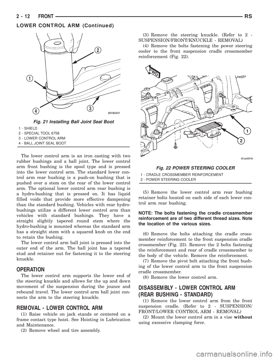
(4) Remove the bolts fastening the power steering
cooler to the front suspension cradle crossmember
reinforcement (Fig. 22).
(5) Remove the lower control arm rear bushing
retainer bolts located on each side of each lower con-
trol arm rear bushing.
NOTE: The bolts fastening the cradle crossmember
reinforcement are of two different thread sizes. Note
the location of the various sizes.
(6) Remove the bolts attaching the cradle cross-
member reinforcement to the front suspension cradle
crossmember (Fig. 23). Remove the 2 bolts fastening
the reinforcement and rear of cradle crossmember to
the body of the vehicle. Remove the reinforcement.
(7) Remove the pivot bolt attaching the front bush-
ing of the lower control arm to the front suspension
cradle crossmember.
(8) Remove the lower control arm.
DISASSEMBLY - LOWER CONTROL ARM
(REAR BUSHING - STANDARD)
(1) Remove the lower control arm from the front
suspension cradle. (Refer to 2 - SUSPENSION/
FRONT/LOWER CONTROL ARM - REMOVAL)
(2) Mount the lower control arm in a visewithout
using excessive clamping force.
Fig. 21 Installing Ball Joint Seal Boot
1 - SHIELD
2 - SPECIAL TOOL 6758
3 - LOWER CONTROL ARM
4 - BALL JOINT SEAL BOOT
Fig. 22 POWER STEERING COOLER
1 - CRADLE CROSSMEMBER REINFORCEMENT
2 - POWER STEERING COOLER
2 - 12 FRONTRS
LOWER CONTROL ARM (Continued)
Page 1532 of 4284
(10) Install the wheel and tire assembly. Install
and tighten the wheel mounting stud nuts in proper
sequence until all nuts are torqued to half specifica-
tion. Then repeat the tightening sequence to the full
specified torque of 135 N´m (100 ft. lbs.).
(11) Raise vehicle, remove jack stands and lower
vehicle to the ground.
(12) Perform front wheel alignment as necessary.
(Refer to 2 - SUSPENSION/WHEEL ALIGNMENT -
STANDARD PROCEDURE)
STABILIZER BAR
DESCRIPTION
The stabilizer bar interconnects both front struts of
the vehicle and is attached to the front crossmember
(Fig. 1) .
Attachment of the stabilizer bar to the front cross-
member is through 2 rubber-isolator cushion bush-
ings and retainers. A double ball jointed stabilizer
bar link is used to attach each end of the stabilizer
bar to the front strut assemblies. All parts of the sta-
bilizer bar are replaceable as individual components.
The stabilizer bar to front crossmember cushion
bushings are split for easy removal and installation.
The split in the bushings should be positioned toward
the rear of the vehicle, with the square corner facing
down, when the stabilizer bar is installed.
OPERATION
Jounce and rebound movements affecting one
wheel are partially transmitted to the opposite wheel
of the vehicle through the stabilizer bar. This helpsto minimize the body roll of the vehicle during sus-
pension movement.
Connecting the stabilizer bar links to the strut
assemblies helps reduce the fore-and-aft rate of the
stabilizer bar from the rest of the front suspension.
REMOVAL - STABILIZER BAR
(1) Raise vehicle on jack stands or centered on a
frame contact type hoist. See Hoisting in Lubrication
and Maintenance.
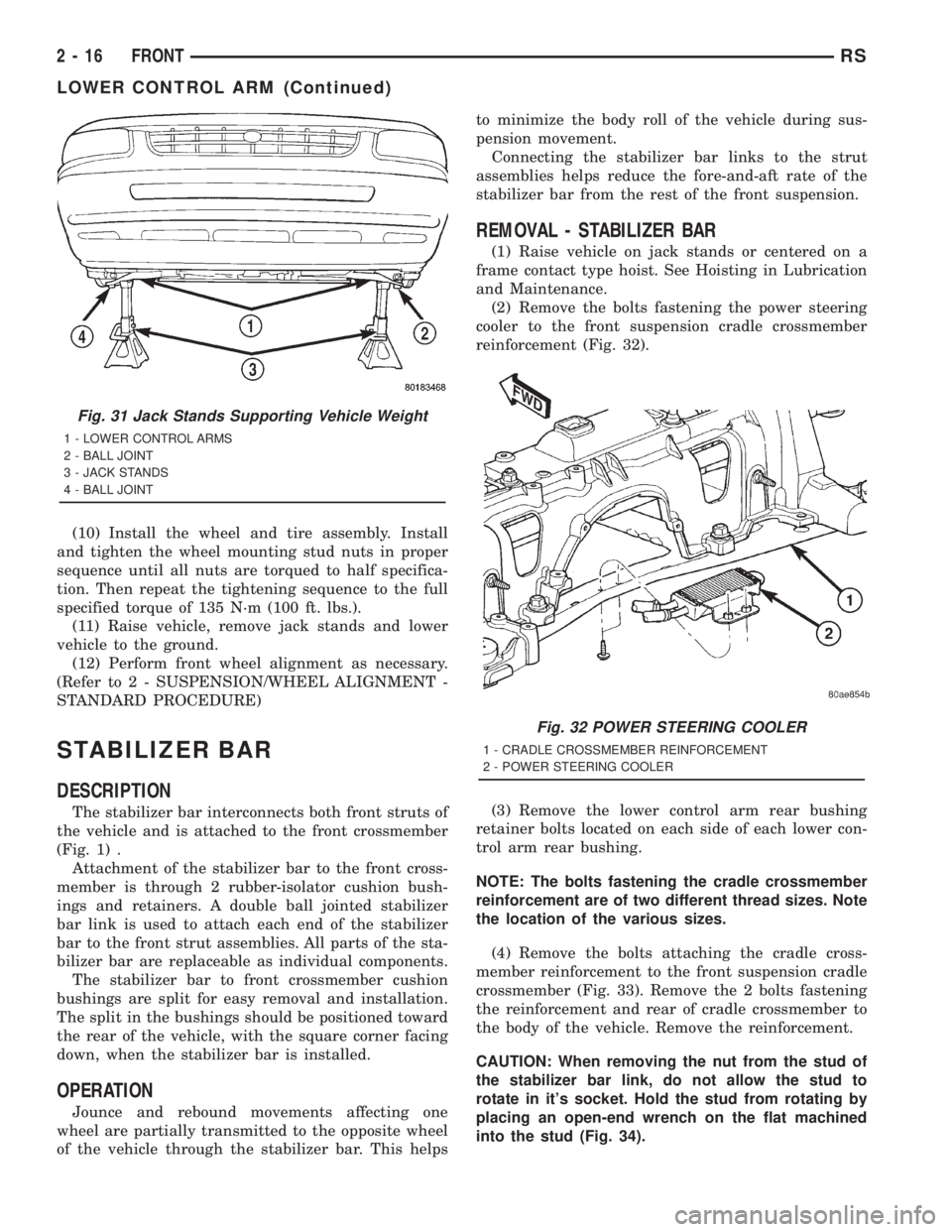
(2) Remove the bolts fastening the power steering
cooler to the front suspension cradle crossmember
reinforcement (Fig. 32).
(3) Remove the lower control arm rear bushing
retainer bolts located on each side of each lower con-
trol arm rear bushing.
NOTE: The bolts fastening the cradle crossmember
reinforcement are of two different thread sizes. Note
the location of the various sizes.
(4) Remove the bolts attaching the cradle cross-
member reinforcement to the front suspension cradle
crossmember (Fig. 33). Remove the 2 bolts fastening
the reinforcement and rear of cradle crossmember to
the body of the vehicle. Remove the reinforcement.
CAUTION: When removing the nut from the stud of
the stabilizer bar link, do not allow the stud to
rotate in it's socket. Hold the stud from rotating by
placing an open-end wrench on the flat machined
into the stud (Fig. 34).
Fig. 31 Jack Stands Supporting Vehicle Weight
1 - LOWER CONTROL ARMS
2 - BALL JOINT
3 - JACK STANDS
4 - BALL JOINT
Fig. 32 POWER STEERING COOLER
1 - CRADLE CROSSMEMBER REINFORCEMENT
2 - POWER STEERING COOLER
2 - 16 FRONTRS
LOWER CONTROL ARM (Continued)
Page 1567 of 4284

CONDITION POSSIBLE CAUSES CORRECTION
Excessive Steering Free
Play1. Incorrect Steering Gear Adjustment 1. Adjust Or Replace Steering Gear
2. Worn or loose tie rod ends 2. Replace or tighten tie rod ends
3. Loose steering gear mounting bolts 3. Tighten steering gear bolts to specified
torque
4. Loose or worn steering shaft coupler 4. Replace steering shaft coupler
Excessive Steering Effort 1. Low tire pressure 1. Inflate all tires to recommended
pressure
2. Lack of lubricant in steering gear 2. Replace steering gear
3. Low power steering fluid level 3. Fill power steering fluid reservoir to
correct level
4. Loose power steering pump drive
belt4. Correctly adjust power steering pump
drive belt
5. Lack of lubricant in ball joints 5. Lubricate or replace ball joints
6. Steering gear malfunction 6. Replace steering gear
7. Lack of lubricant in steering coupler 7. Replace steering coupler
STANDARD PROCEDURE - WHEEL ALIGNMENT
PRE-WHEEL ALIGNMENT INSPECTION
Before any attempt is made to change or correct
the wheel alignment, the following inspection and
necessary corrections must be made to ensure proper
alignment.
(1) Verify that the fuel tank is full of fuel. If the
tank is not full, the reduction in weight will affect
the curb height of the vehicle and the alignment
angles.
(2) The passenger and luggage compartments of
the vehicle should be free of any load that is not fac-
tory equipment.
(3) Check the tires on the vehicle. All tires must be
the same size and in good condition with approxi-
mately the same amount of tread wear. Inflate all
the tires to the recommended air pressure.
(4) Check the front wheel and tire assemblies for
excessive radial runout.
(5) Inspect lower ball joints and all steering link-
age for looseness, binding, wear or damage. Repair as
necessary.
(6) Check suspension fasteners for proper torque
and retighten as necessary.
(7) Inspect all suspension component rubber bush-
ings for signs of wear or deterioration. Replace any
faulty bushings or components before aligning the
vehicle.
(8) Check the vehicle's curb height to verify it is
within specifications. Refer to Curb Height Measure-
ment.
WHEEL ALIGNMENT SETUP
(1) Position the vehicle on an alignment rack.
(2) Install all required alignment equipment on
the vehicle per the alignment equipment manufactur-
er's instructions. On this vehicle, a four-wheel align-
ment is recommended.
NOTE: Prior to reading the vehicle's alignment
readouts, the front and rear of vehicle should be
jounced. Induce jounce (rear first, then front) by
grasping the center of the bumper and jouncing
each end of vehicle an equal number of times. The
bumper should always be released when vehicle is
at the bottom of the jounce cycle.
(3) Read the vehicle's current front and rear align-
ment settings. Compare the vehicle's current align-
ment settings to the vehicle specifications for camber,
caster and toe-in. (Refer to 2 - SUSPENSION/
WHEEL ALIGNMENT - SPECIFICATIONS)
(4) If front camber and caster are not within spec-
ifications, proceed to CAMBER AND CASTER below.
If caster and camber are within specifications, pro-
ceed to TOE which can be found following CAMBER
AND CASTER. Rear camber, caster and toe are not
adjustable. If found not to be within specifications,
reinspect for damaged suspension or body compo-
nents and replace as necessary.
CAMBER AND CASTER
Camber and caster settings on this vehicle are
determined at the time the vehicle is designed, by
the location of the vehicle's suspension components.
This is referred to as NET BUILD. The result is no
RSWHEEL ALIGNMENT2-51
WHEEL ALIGNMENT (Continued)
Page 1570 of 4284
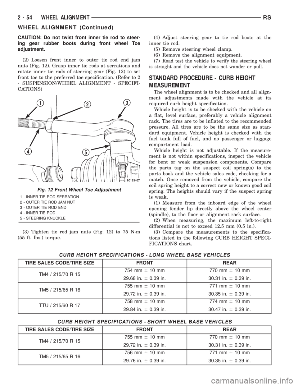
CAUTION: Do not twist front inner tie rod to steer-
ing gear rubber boots during front wheel Toe
adjustment.
(2) Loosen front inner to outer tie rod end jam
nuts (Fig. 12). Grasp inner tie rods at serrations and
rotate inner tie rods of steering gear (Fig. 12) to set
front toe to the preferred toe specification. (Refer to 2
- SUSPENSION/WHEEL ALIGNMENT - SPECIFI-
CATIONS)
(3) Tighten tie rod jam nuts (Fig. 12) to 75 N´m
(55 ft. lbs.) torque.(4) Adjust steering gear to tie rod boots at the
inner tie rod.
(5) Remove steering wheel clamp.
(6) Remove the alignment equipment.
(7)
Road test the vehicle to verify the steering wheel
is straight and the vehicle does not wander or pull.
STANDARD PROCEDURE - CURB HEIGHT
MEASUREMENT
The wheel alignment is to be checked and all align-
ment adjustments made with the vehicle at its
required curb height specification.
Vehicle height is to be checked with the vehicle on
a flat, level surface, preferably a vehicle alignment
rack. The tires are to be inflated to the recommended
pressure. All tires are to be the same size as stan-
dard equipment. Vehicle height is checked with the
fuel tank full of fuel, and no passenger or luggage
compartment load.
Vehicle height is not adjustable. If the measure-
ment is not within specifications, inspect the vehicle
for bent or weak suspension components. Compare
the parts tag on the suspect coil spring(s) to the
parts book and the vehicle sales code, checking for a
match. Once removed from the vehicle, compare the
coil spring height to a correct new or known good coil
spring. The heights should vary if the suspect spring
is weak.
(1) Measure from the inboard edge of the wheel
opening fender lip directly above the wheel center
(spindle), to the floor or alignment rack surface.
(2) When measuring, the maximum left-to-right
differential is not to exceed 12.5 mm (0.5 in.).
(3) Compare the measurements to the specifica-
tions listed in the following CURB HEIGHT SPECI-
FICATIONS chart.
CURB HEIGHT SPECIFICATIONS - LONG WHEEL BASE VEHICLES
TIRE SALES CODE/TIRE SIZE FRONT REAR
TM4 / 215/70 R 15754 mm610 mm 770 mm610 mm
29.68 in.60.39 in. 30.31 in.60.39 in.
TM5 / 215/65 R 16755 mm610 mm 771 mm610 mm
29.72 in.60.39 in. 30.35 in.60.39 in.
TTU / 215/60 R 17758 mm610 mm 774 mm610 mm
29.84 in.60.39 in. 30.47 in.60.39 in.
CURB HEIGHT SPECIFICATIONS - SHORT WHEEL BASE VEHICLES
TIRE SALES CODE/TIRE SIZE FRONT REAR
TM4 / 215/70 R 15755 mm610 mm 770 mm610 mm
29.72 in.60.39 in. 30.31 in.60.39 in.
TM5 / 215/65 R 16756 mm610 mm 771 mm610 mm
29.76 in.60.39 in. 30.35 in.60.39 in.
Fig. 12 Front Wheel Toe Adjustment
1 - INNER TIE ROD SERRATION
2 - OUTER TIE ROD JAM NUT
3 - OUTER TIE ROD END
4 - INNER TIE ROD
5 - STEERING KNUCKLE
2 - 54 WHEEL ALIGNMENTRS
WHEEL ALIGNMENT (Continued)
Page 1575 of 4284
WHEEL ALIGNMENT
TABLE OF CONTENTS
page page
WHEEL ALIGNMENT
STANDARD PROCEDURE...................3CURB HEIGHT MEASUREMENT............3
WHEEL ALIGNMENT
STANDARD PROCEDURE - CURB HEIGHT
MEASUREMENT
The wheel alignment is to be checked and all align-
ment adjustments made with the vehicle at its
required curb height specification.
Vehicle height is to be checked with the vehicle on
a flat, level surface, preferably a vehicle alignment
rack. The tires are to be inflated to the recommended
pressure. All tires are to be the same size as stan-
dard equipment. Vehicle height is checked with the
fuel tank full of fuel, and no passenger or luggage
compartment load.
Vehicle height is not adjustable. If the measure-
ment is not within specifications, inspect the vehiclefor bent or weak suspension components. Compare
the parts tag on the suspect coil spring(s) to the
parts book and the vehicle sales code, checking for a
match. Once removed from the vehicle, compare the
coil spring height to a correct new or known good coil
spring. The heights should vary if the suspect spring
is weak.
(1) Measure from the inboard edge of the wheel
opening fender lip directly above the wheel center
(spindle), to the floor or alignment rack surface.
(2) When measuring, the maximum left-to-right
differential is not to exceed 12.5 mm (0.5 in.).
(3) Compare the measurements to the specifica-
tions listed in the following Curb Height Specifica-
tions charts.
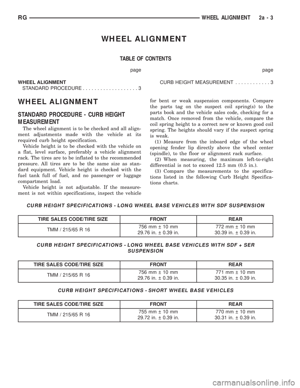
CURB HEIGHT SPECIFICATIONS - LONG WHEEL BASE VEHICLES WITH SDF SUSPENSION
TIRE SALES CODE/TIRE SIZE FRONT REAR
TMM / 215/65 R 16756mm 10mm
29.76 in. 0.39 in.772mm 10mm
30.39 in. 0.39 in.
CURB HEIGHT SPECIFICATIONS - LONG WHEEL BASE VEHICLES WITH SDF + SER
SUSPENSION
TIRE SALES CODE/TIRE SIZE FRONT REAR
TMM / 215/65 R 16756mm 10mm
29.76 in. 0.39 in.771mm 10mm
30.35 in. 0.39 in.
CURB HEIGHT SPECIFICATIONS - SHORT WHEEL BASE VEHICLES
TIRE SALES CODE/TIRE SIZE FRONT REAR
TMM / 215/65 R 16755mm 10mm
29.72 in. 0.39 in.770mm 10mm
30.31 in. 0.39 in.
RGWHEEL ALIGNMENT2a-3
Page 1605 of 4284
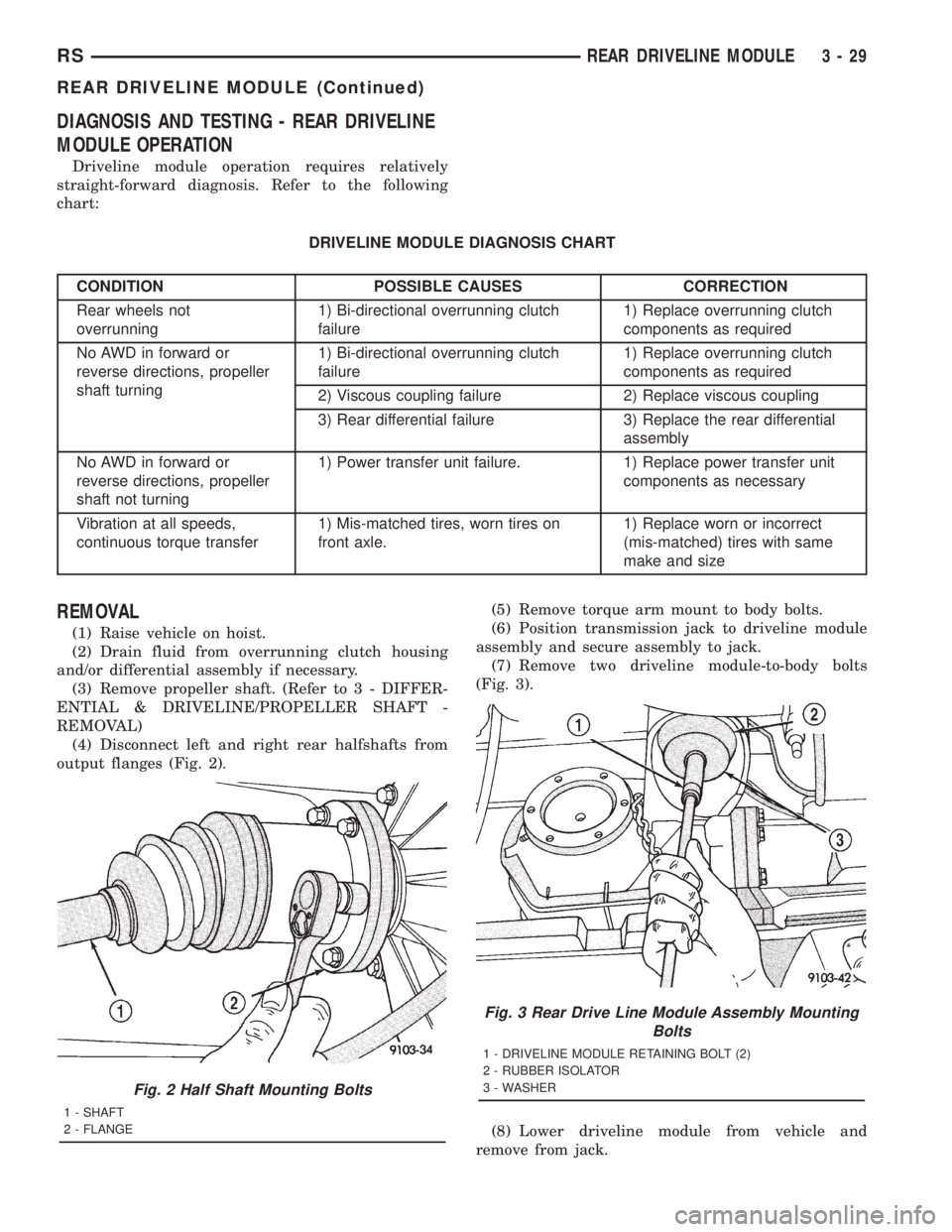
DIAGNOSIS AND TESTING - REAR DRIVELINE
MODULE OPERATION
Driveline module operation requires relatively
straight-forward diagnosis. Refer to the following
chart:
DRIVELINE MODULE DIAGNOSIS CHART
CONDITION POSSIBLE CAUSES CORRECTION
Rear wheels not
overrunning1) Bi-directional overrunning clutch
failure1) Replace overrunning clutch
components as required
No AWD in forward or
reverse directions, propeller
shaft turning1) Bi-directional overrunning clutch
failure1) Replace overrunning clutch
components as required
2) Viscous coupling failure 2) Replace viscous coupling
3) Rear differential failure 3) Replace the rear differential
assembly
No AWD in forward or
reverse directions, propeller
shaft not turning1) Power transfer unit failure. 1) Replace power transfer unit
components as necessary
Vibration at all speeds,
continuous torque transfer1) Mis-matched tires, worn tires on
front axle.1) Replace worn or incorrect
(mis-matched) tires with same
make and size
REMOVAL
(1) Raise vehicle on hoist.
(2) Drain fluid from overrunning clutch housing
and/or differential assembly if necessary.
(3) Remove propeller shaft. (Refer to 3 - DIFFER-
ENTIAL & DRIVELINE/PROPELLER SHAFT -
REMOVAL)
(4) Disconnect left and right rear halfshafts from
output flanges (Fig. 2).(5) Remove torque arm mount to body bolts.
(6) Position transmission jack to driveline module
assembly and secure assembly to jack.
(7) Remove two driveline module-to-body bolts
(Fig. 3).
(8) Lower driveline module from vehicle and
remove from jack.
Fig. 2 Half Shaft Mounting Bolts
1 - SHAFT
2 - FLANGE
Fig. 3 Rear Drive Line Module Assembly Mounting
Bolts
1 - DRIVELINE MODULE RETAINING BOLT (2)
2 - RUBBER ISOLATOR
3 - WASHER
RSREAR DRIVELINE MODULE3-29
REAR DRIVELINE MODULE (Continued)