2001 CHRYSLER VOYAGER wheel size
[x] Cancel search: wheel sizePage 2960 of 4284
INSTALLATION - RHD GEAR
(1) Install the steering gear up in the front sus-
pension cradle crossmember, leaving room to install
intermediate coupler.
(2) Start the roll pin into the intermediate coupler
before installing coupler on steering gear shaft. Start
roll pin into coupler, using a hammer and tapping it
into the coupler. Then install the intermediate cou-
pler on the shaft of the steering gear.
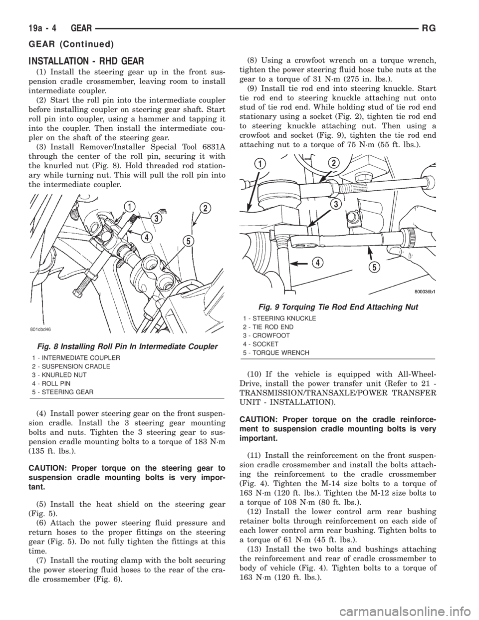
(3) Install Remover/Installer Special Tool 6831A
through the center of the roll pin, securing it with
the knurled nut (Fig. 8). Hold threaded rod station-
ary while turning nut. This will pull the roll pin into
the intermediate coupler.
(4) Install power steering gear on the front suspen-
sion cradle. Install the 3 steering gear mounting
bolts and nuts. Tighten the 3 steering gear to sus-
pension cradle mounting bolts to a torque of 183 N´m
(135 ft. lbs.).
CAUTION: Proper torque on the steering gear to
suspension cradle mounting bolts is very impor-
tant.
(5) Install the heat shield on the steering gear
(Fig. 5).
(6) Attach the power steering fluid pressure and
return hoses to the proper fittings on the steering
gear (Fig. 5). Do not fully tighten the fittings at this
time.
(7) Install the routing clamp with the bolt securing
the power steering fluid hoses to the rear of the cra-
dle crossmember (Fig. 6).(8) Using a crowfoot wrench on a torque wrench,
tighten the power steering fluid hose tube nuts at the
gear to a torque of 31 N´m (275 in. lbs.).
(9) Install tie rod end into steering knuckle. Start
tie rod end to steering knuckle attaching nut onto
stud of tie rod end. While holding stud of tie rod end
stationary using a socket (Fig. 2), tighten tie rod end
to steering knuckle attaching nut. Then using a
crowfoot and socket (Fig. 9), tighten the tie rod end
attaching nut to a torque of 75 N´m (55 ft. lbs.).
(10) If the vehicle is equipped with All-Wheel-
Drive, install the power transfer unit (Refer to 21 -
TRANSMISSION/TRANSAXLE/POWER TRANSFER
UNIT - INSTALLATION).
CAUTION: Proper torque on the cradle reinforce-
ment to suspension cradle mounting bolts is very
important.
(11) Install the reinforcement on the front suspen-
sion cradle crossmember and install the bolts attach-
ing the reinforcement to the cradle crossmember
(Fig. 4). Tighten the M-14 size bolts to a torque of
163 N´m (120 ft. lbs.). Tighten the M-12 size bolts to
a torque of 108 N´m (80 ft. lbs.).
(12) Install the lower control arm rear bushing
retainer bolts through reinforcement on each side of
each lower control arm rear bushing. Tighten bolts to
a torque of 61 N´m (45 ft. lbs.).
(13) Install the two bolts and bushings attaching
the reinforcement and rear of cradle crossmember to
body of vehicle (Fig. 4). Tighten bolts to a torque of
163 N´m (120 ft. lbs.).
Fig. 8 Installing Roll Pin In Intermediate Coupler
1 - INTERMEDIATE COUPLER
2 - SUSPENSION CRADLE
3 - KNURLED NUT
4 - ROLL PIN
5 - STEERING GEAR
Fig. 9 Torquing Tie Rod End Attaching Nut
1 - STEERING KNUCKLE
2 - TIE ROD END
3 - CROWFOOT
4 - SOCKET
5 - TORQUE WRENCH
19a - 4 GEARRG
GEAR (Continued)
Page 3298 of 4284
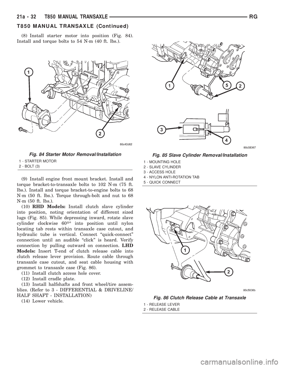
(8) Install starter motor into position (Fig. 84).
Install and torque bolts to 54 N´m (40 ft. lbs.).
(9) Install engine front mount bracket. Install and
torque bracket-to-transaxle bolts to 102 N´m (75 ft.
lbs.). Install and torque bracket-to-engine bolts to 68
N´m (50 ft. lbs.). Torque through-bolt and nut to 68
N´m (50 ft. lbs.).
(10)RHD Models:Install clutch slave cylinder
into position, noting orientation of different sized
lugs (Fig. 85). While depressing inward, rotate slave
cylinder clockwise 60tÉ into position until nylon
locating tab rests within transaxle case cutout, and
hydraulic tube is vertical. Connect ªquick-connectº
connection until an audible ªclickº is heard. Verify
connection by pulling outward on connection.LHD
Models:Insert T-end of clutch release cable into
clutch release lever provision. Route cable through
transaxle case cutout, and seat cable housing with
grommet to transaxle case (Fig. 86).
(11) Install clutch access hole cover.
(12) Install cradle plate.
(13) Install halfshafts and front wheel/tire assem-
blies. (Refer to 3 - DIFFERENTIAL & DRIVELINE/
HALF SHAFT - INSTALLATION)
(14) Lower vehicle.
Fig. 84 Starter Motor Removal/Installation
1 - STARTER MOTOR
2 - BOLT (3)
Fig. 85 Slave Cylinder Removal/Installation
1 - MOUNTING HOLE
2 - SLAVE CYLINDER
3 - ACCESS HOLE
4 - NYLON ANTI-ROTATION TAB
5 - QUICK CONNECT
Fig. 86 Clutch Release Cable at Transaxle
1 - RELEASE LEVER
2 - RELEASE CABLE
21a - 32 T850 MANUAL TRANSAXLERG
T850 MANUAL TRANSAXLE (Continued)
Page 3301 of 4284
(8) Install engine front mount bracket. Install and
torque bracket-to-transaxle bolts to 102 N´m (75 ft.
lbs.). Install and torque bracket-to-engine bolts to 68
N´m (50 ft. lbs.). Torque through-bolt and nut to 68
N´m (50 ft. lbs.).
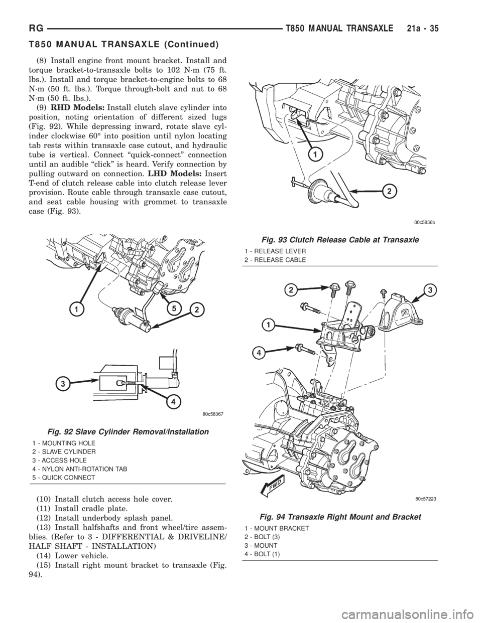
(9)RHD Models:Install clutch slave cylinder into
position, noting orientation of different sized lugs
(Fig. 92). While depressing inward, rotate slave cyl-
inder clockwise 60É into position until nylon locating
tab rests within transaxle case cutout, and hydraulic
tube is vertical. Connect ªquick-connectº connection
until an audible ªclickº is heard. Verify connection by
pulling outward on connection.LHD Models:Insert
T-end of clutch release cable into clutch release lever
provision. Route cable through transaxle case cutout,
and seat cable housing with grommet to transaxle
case (Fig. 93).
(10) Install clutch access hole cover.
(11) Install cradle plate.
(12) Install underbody splash panel.
(13) Install halfshafts and front wheel/tire assem-
blies. (Refer to 3 - DIFFERENTIAL & DRIVELINE/
HALF SHAFT - INSTALLATION)
(14) Lower vehicle.
(15) Install right mount bracket to transaxle (Fig.
94).
Fig. 92 Slave Cylinder Removal/Installation
1 - MOUNTING HOLE
2 - SLAVE CYLINDER
3 - ACCESS HOLE
4 - NYLON ANTI-ROTATION TAB
5 - QUICK CONNECT
Fig. 93 Clutch Release Cable at Transaxle
1 - RELEASE LEVER
2 - RELEASE CABLE
Fig. 94 Transaxle Right Mount and Bracket
1 - MOUNT BRACKET
2 - BOLT (3)
3 - MOUNT
4 - BOLT (1)
RGT850 MANUAL TRANSAXLE21a-35
T850 MANUAL TRANSAXLE (Continued)
Page 3370 of 4284
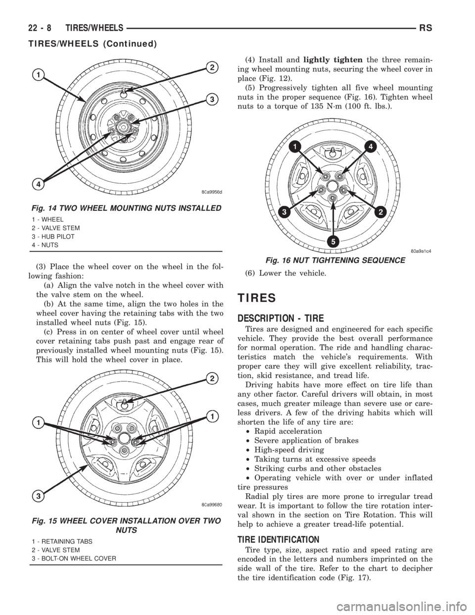
(3) Place the wheel cover on the wheel in the fol-
lowing fashion:
(a) Align the valve notch in the wheel cover with
the valve stem on the wheel.
(b) At the same time, align the two holes in the
wheel cover having the retaining tabs with the two
installed wheel nuts (Fig. 15).
(c) Press in on center of wheel cover until wheel
cover retaining tabs push past and engage rear of
previously installed wheel mounting nuts (Fig. 15).
This will hold the wheel cover in place.(4) Install andlightly tightenthe three remain-
ing wheel mounting nuts, securing the wheel cover in
place (Fig. 12).
(5) Progressively tighten all five wheel mounting
nuts in the proper sequence (Fig. 16). Tighten wheel
nuts to a torque of 135 N´m (100 ft. lbs.).
(6) Lower the vehicle.
TIRES
DESCRIPTION - TIRE
Tires are designed and engineered for each specific
vehicle. They provide the best overall performance
for normal operation. The ride and handling charac-
teristics match the vehicle's requirements. With
proper care they will give excellent reliability, trac-
tion, skid resistance, and tread life.
Driving habits have more effect on tire life than
any other factor. Careful drivers will obtain, in most
cases, much greater mileage than severe use or care-
less drivers. A few of the driving habits which will
shorten the life of any tire are:
²Rapid acceleration
²Severe application of brakes
²High-speed driving
²Taking turns at excessive speeds
²Striking curbs and other obstacles
²Operating vehicle with over or under inflated
tire pressures
Radial ply tires are more prone to irregular tread
wear. It is important to follow the tire rotation inter-
val shown in the section on Tire Rotation. This will
help to achieve a greater tread-life potential.
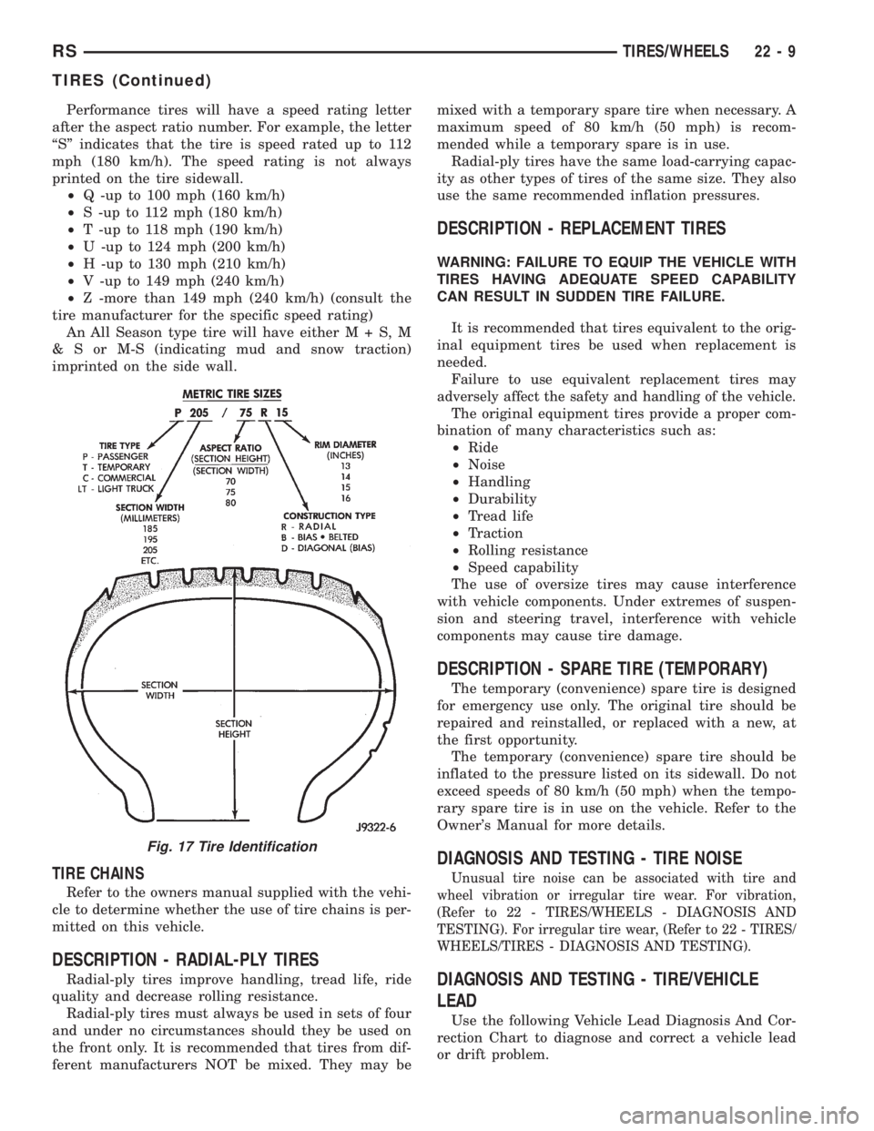
TIRE IDENTIFICATION
Tire type, size, aspect ratio and speed rating are
encoded in the letters and numbers imprinted on the
side wall of the tire. Refer to the chart to decipher
the tire identification code (Fig. 17).
Fig. 14 TWO WHEEL MOUNTING NUTS INSTALLED
1 - WHEEL
2 - VALVE STEM
3 - HUB PILOT
4 - NUTS
Fig. 15 WHEEL COVER INSTALLATION OVER TWO
NUTS
1 - RETAINING TABS
2 - VALVE STEM
3 - BOLT-ON WHEEL COVER
Fig. 16 NUT TIGHTENING SEQUENCE
22 - 8 TIRES/WHEELSRS
TIRES/WHEELS (Continued)
Page 3371 of 4284
Performance tires will have a speed rating letter
after the aspect ratio number. For example, the letter
ªSº indicates that the tire is speed rated up to 112
mph (180 km/h). The speed rating is not always
printed on the tire sidewall.
²Q -up to 100 mph (160 km/h)
²S -up to 112 mph (180 km/h)
²T -up to 118 mph (190 km/h)
²U -up to 124 mph (200 km/h)
²H -up to 130 mph (210 km/h)
²V -up to 149 mph (240 km/h)
²Z -more than 149 mph (240 km/h) (consult the
tire manufacturer for the specific speed rating)
An All Season type tire will have eitherM+S,M
& S or M-S (indicating mud and snow traction)
imprinted on the side wall.
TIRE CHAINS
Refer to the owners manual supplied with the vehi-
cle to determine whether the use of tire chains is per-
mitted on this vehicle.
DESCRIPTION - RADIAL-PLY TIRES
Radial-ply tires improve handling, tread life, ride
quality and decrease rolling resistance.
Radial-ply tires must always be used in sets of four
and under no circumstances should they be used on
the front only. It is recommended that tires from dif-
ferent manufacturers NOT be mixed. They may bemixed with a temporary spare tire when necessary. A
maximum speed of 80 km/h (50 mph) is recom-
mended while a temporary spare is in use.
Radial-ply tires have the same load-carrying capac-
ity as other types of tires of the same size. They also
use the same recommended inflation pressures.
DESCRIPTION - REPLACEMENT TIRES
WARNING: FAILURE TO EQUIP THE VEHICLE WITH
TIRES HAVING ADEQUATE SPEED CAPABILITY
CAN RESULT IN SUDDEN TIRE FAILURE.
It is recommended that tires equivalent to the orig-
inal equipment tires be used when replacement is
needed.
Failure to use equivalent replacement tires may
adversely affect the safety and handling of the vehicle.
The original equipment tires provide a proper com-
bination of many characteristics such as:
²Ride
²Noise
²Handling
²Durability
²Tread life
²Traction
²Rolling resistance
²Speed capability
The use of oversize tires may cause interference
with vehicle components. Under extremes of suspen-
sion and steering travel, interference with vehicle
components may cause tire damage.
DESCRIPTION - SPARE TIRE (TEMPORARY)
The temporary (convenience) spare tire is designed
for emergency use only. The original tire should be
repaired and reinstalled, or replaced with a new, at
the first opportunity.
The temporary (convenience) spare tire should be
inflated to the pressure listed on its sidewall. Do not
exceed speeds of 80 km/h (50 mph) when the tempo-
rary spare tire is in use on the vehicle. Refer to the
Owner's Manual for more details.
DIAGNOSIS AND TESTING - TIRE NOISE
Unusual tire noise can be associated with tire and
wheel vibration or irregular tire wear. For vibration,
(Refer to 22 - TIRES/WHEELS - DIAGNOSIS AND
TESTING). For irregular tire wear, (Refer to 22 - TIRES/
WHEELS/TIRES - DIAGNOSIS AND TESTING).
DIAGNOSIS AND TESTING - TIRE/VEHICLE
LEAD
Use the following Vehicle Lead Diagnosis And Cor-
rection Chart to diagnose and correct a vehicle lead
or drift problem.
Fig. 17 Tire Identification
RSTIRES/WHEELS22-9
TIRES (Continued)
Page 3376 of 4284
CLEANING - ALUMINUM WHEEL CARE
Chrome plated and painted aluminum wheels
should be cleaned regularly using mild soap and
water to maintain their luster and to prevent corro-
sion.
Care must be taken in the selection of tire and
wheel cleaning chemicals and equipment to prevent
damage to the wheels. Any of the ªDO NOT USEº
items listed below WILL damage chrome plated and
painted aluminum wheels.
DO NOT USE:
²any abrasive metal cleaner
²any abrasive cleaning pad or brush
²any cleaner that contains an acid (this will
immediately react with and discolor the chromium
surface)
²chrome polish (unless it is buffed off immedi-
ately after application)
²oven cleaner
²a car wash that uses carbide-tipped wheel clean-
ing brushes
SPECIFICATIONS
WHEEL
SPECIFICATIONS
DESCRIPTION SPECIFICATION
Wheel Mounting (Lug)
Nut Hex Size19 mm
Wheel Mounting Stud
SizeM12 x 1.5 mm
TORQUE SPECIFICATIONS
DESCRIPTION N´mFt.
Lbs.In.
Lbs.
Wheel Mounting (Lug ) Nut 135 100 Ð
WHEEL COVER
DESCRIPTION
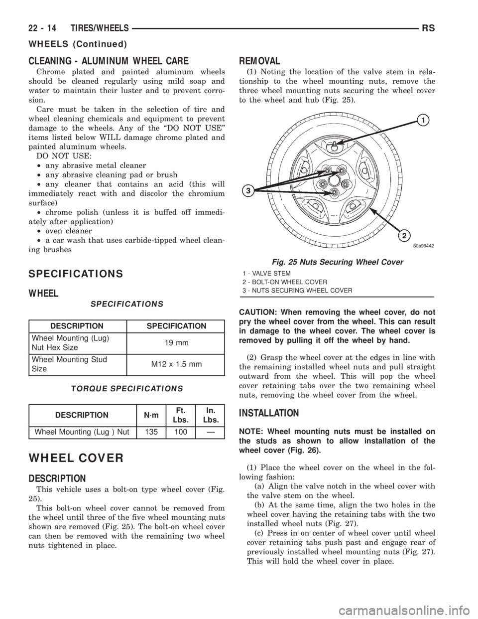
This vehicle uses a bolt-on type wheel cover (Fig.
25).
This bolt-on wheel cover cannot be removed from
the wheel until three of the five wheel mounting nuts
shown are removed (Fig. 25). The bolt-on wheel cover
can then be removed with the remaining two wheel
nuts tightened in place.
REMOVAL
(1) Noting the location of the valve stem in rela-
tionship to the wheel mounting nuts, remove the
three wheel mounting nuts securing the wheel cover
to the wheel and hub (Fig. 25).
CAUTION: When removing the wheel cover, do not
pry the wheel cover from the wheel. This can result
in damage to the wheel cover. The wheel cover is
removed by pulling it off the wheel by hand.
(2) Grasp the wheel cover at the edges in line with
the remaining installed wheel nuts and pull straight
outward from the wheel. This will pop the wheel
cover retaining tabs over the two remaining wheel
nuts, removing the wheel cover from the wheel.
INSTALLATION
NOTE: Wheel mounting nuts must be installed on
the studs as shown to allow installation of the
wheel cover (Fig. 26).
(1) Place the wheel cover on the wheel in the fol-
lowing fashion:
(a) Align the valve notch in the wheel cover with
the valve stem on the wheel.
(b) At the same time, align the two holes in the
wheel cover having the retaining tabs with the two
installed wheel nuts (Fig. 27).
(c) Press in on center of wheel cover until wheel
cover retaining tabs push past and engage rear of
previously installed wheel mounting nuts (Fig. 27).
This will hold the wheel cover in place.
Fig. 25 Nuts Securing Wheel Cover
1 - VALVE STEM
2 - BOLT-ON WHEEL COVER
3 - NUTS SECURING WHEEL COVER
22 - 14 TIRES/WHEELSRS
WHEELS (Continued)
Page 3386 of 4284
VISUAL INSPECTION
Sheet Molded Compound (SMC) and Resin Trans-
fer Molded (RTM), because they are composites, react
differently to impact that sheet metal does. Compos-
ite materials can mask the severity of an accident.
Adhesive bond lines, interior structure of the doors,
and steel structure need to be inspected carefully to
get a true damage assessment. Close inspection may
require partial removal of interior trim or inner pan-
els.
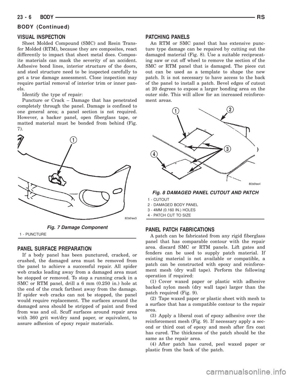
Identify the type of repair:
Puncture or Crack ± Damage that has penetrated
completely through the panel. Damage is confined to
one general area; a panel section is not required.
However, a backer panel, open fiberglass tape, or
matted material must be bonded from behind (Fig.
7).
PANEL SURFACE PREPARATION
If a body panel has been punctured, cracked, or
crushed, the damaged area must be removed from
the panel to achieve a successful repair. All spider
web cracks leading away from a damaged area must
be stopped or removed. To stop a running crack in a
SMC or RTM panel, drilla6mm(0.250 in.) hole at
the end of the crack farthest away from the damage.
If spider web cracks can not be stopped, the panel
would require replacement. The surfaces around the
damaged area should be stripped of paint and freed
from was and oil. Scuff surfaces around repair area
with 360 grit wet/dry sand paper, or equivalent, to
assure adhesion of epoxy repair materials.
PATCHING PANELS
An RTM or SMC panel that has extensive punc-
ture type damage can be repaired by cutting out the
damaged material (Fig. 8). Use a suitable reciprocat-
ing saw or cut off wheel to remove the section of the
SMC or RTM panel that is damaged. The piece cut
out can be used as a template to shape the new
patch. It is not necessary to have access to the back
of the panel to install a patch. Bevel edges of cutout
at 20 degrees to expose a larger bonding area on the
outer side. This will allow for an increased reinforce-
ment areas.
PANEL PATCH FABRICATIONS
A patch can be fabricated from any rigid fiberglass
panel that has comparable contour with the repair
area. discard SMC or RTM panels. Lift gates and
fenders can be used to supply patch material. If
existing material is not available or compatible, a
patch can be constructed with epoxy and reinforce-
ment mesh (dry wall tape). Perform the following
operation if required:
(1) Cover waxed paper or plastic with adhesive
backed nylon mesh (dry wall tape) larger than the
patch required (Fig. 9).
(2) Tape waxed paper or plastic sheet with mesh to
a surface that has a compatible contour to the repair
area.
(3) Apply a liberal coat of epoxy adhesive over the
reinforcement mesh (Fig. 9). If necessary apply a sec-
ond or third coat of epoxy and mesh after firs coat
has cured. The thickness of the patch should be the
same as the repair area.
(4) After patch has cured, peel waxed paper or
plastic from the back of the patch.
Fig. 7 Damage Component
1 - PUNCTURE
Fig. 8 DAMAGED PANEL CUTOUT AND PATCH
1 - CUTOUT
2 - DAMAGED BODY PANEL
3 - 4MM (0.160 IN.) HOLES
4 - PATCH CUT TO SIZE
23 - 6 BODYRS
BODY (Continued)
Page 3710 of 4284
INSTALLATION - HEATER CORE
WARNING: REFER TO THE APPLICABLE WARN-
INGS AND CAUTIONS FOR THIS SYSTEM BEFORE
PERFORMING THE FOLLOWING OPERATION.
(Refer to 24 - HEATING & AIR CONDITIONING/
PLUMBING FRONT - WARNING - HEATER PLUMB-
ING).
WARNING: ON VEHICLES EQUIPPED WITH AIR-
BAGS, DISABLE THE AIRBAG SYSTEM BEFORE
ATTEMPTING ANY STEERING WHEEL, STEERING
COLUMN, OR INSTRUMENT PANEL COMPONENT
DIAGNOSIS OR SERVICE. DISCONNECT AND ISO-
LATE THE BATTERY NEGATIVE (GROUND) CABLE,
THEN WAIT TWO MINUTES FOR THE AIRBAG SYS-
TEM CAPACITOR TO DISCHARGE BEFORE PER-
FORMING FURTHER DIAGNOSIS OR SERVICE. THIS
IS THE ONLY SURE WAY TO DISABLE THE AIRBAG
SYSTEM. FAILURE TO TAKE THE PROPER PRE-
CAUTIONS COULD RESULT IN ACCIDENTAL AIR-
BAG DEPLOYMENT AND POSSIBLE PERSONAL
INJURY.
(1) While pushing the brake pedal downward (Fig.
20) and pulling the accelerator pedal upward (Fig.
19) far enough for clearance, slide the heater core
into the distribution housing.
(2) Install and tighten the two screws that secure
the heater core mounting plate to the distribution
housing (Fig. 18). Tighten the screws to 2 N´m (17 in.
lbs.).
(3) Remove the plugs or tape from the heater core
tube fittings and both heater core ports.
(4) Position both heater core tubes and the sealing
plate simultaneously to the heater core supply and
return ports.
(5) The heater core tubes each have a slot that
must be indexed to a location tab within each of the
heater core ports. Adjust the position of the tubes as
required so that the sealing plate fits flush against
the heater core supply and return ports, which indi-
cates that the tubes are properly indexed.
(6) Install and tighten the screw that secures the
heater core tube sealing plate to the heater core sup-
ply and return ports. Tighten the screw to 3 N´m (27
in. lbs.).
(7) Position the heater core shield onto the distri-
bution housing. Be certain that the two location tabs
on the front of the shield are engaged in the recepta-
cles in the two lower finger formations of the evapo-
rator housing near the dash panel (Fig. 17).
(8) Install and tighten the three screws that secure
the heater core shield to the left end of the HVAC
distribution housing. Tighten the screws to 2 N´m (17
in. lbs.).(9) Reconnect the power brake booster input rod
(push rod) to the pin on the brake pedal arm. (Refer
to 5 - BRAKES - ABS/HYDRAULIC/MECHANICAL/
POWER BRAKE BOOSTER - INSTALLATION).
(10) Reinstall the brake lamp switch into its
mounting bracket. (Refer to 8 - ELECTRICAL/
LAMPS/LIGHTING - EXTERIOR/BRAKE LAMP
SWITCH - INSTALLATION).
(11) Reinstall the silencer boot around the base of
the lower steering shaft on the dash panel.
(12) Reconnect the battery negative cable.
(13) Refill the engine cooling system. (Refer to 7 -
COOLING - STANDARD PROCEDURE - COOLING
SYSTEM REFILL).
(14) Operate sustem for two thermostat cycles to
assure elimination of air in the system.
HEATER HOSE
REMOVAL
There are several heater core plumbing configura-
tions used on this model, depending upon the engine
size and other optional equipment. One plumbing
configuration is used for all 2.4L engines (Fig. 21),
while the 3.3L and 3.8L engines have unique heater
return plumbing on the engine for models with or
without an optional engine oil cooler (Fig. 24) or (Fig.
25). There are also unique plumbing configurations
at the heater core for models with or without the
optional rear heater and air conditioner (Fig. 22) or
(Fig. 23). All models use a combination of formed
steel tubing and rubber hoses. In most cases, the
rubber hose is secured to the steel tubing with a
spring tension clamp.
WARNING: REFER TO THE APPLICABLE WARN-
INGS AND CAUTIONS FOR THIS SYSTEM BEFORE
PERFORMING THE FOLLOWING OPERATION.
(Refer to 24 - HEATING & AIR CONDITIONING/
PLUMBING FRONT - WARNING - HEATER PLUMB-
ING).
(1) Drain the engine cooling system. (Refer to 7 -
COOLING - STANDARD PROCEDURE - COOLING
SYSTEM DRAIN).
(2) Using spring tension clamp pliers, compress
and slide the clamps that secure each end of the
heater hose to the tube or nipple toward the center of
the hose to be removed. Release the clamp when it is
off of the tube or nipple.
24 - 80 PLUMBING - FRONTRS
HEATER CORE (Continued)