2001 CHRYSLER VOYAGER parking sensors
[x] Cancel search: parking sensorsPage 1159 of 4284
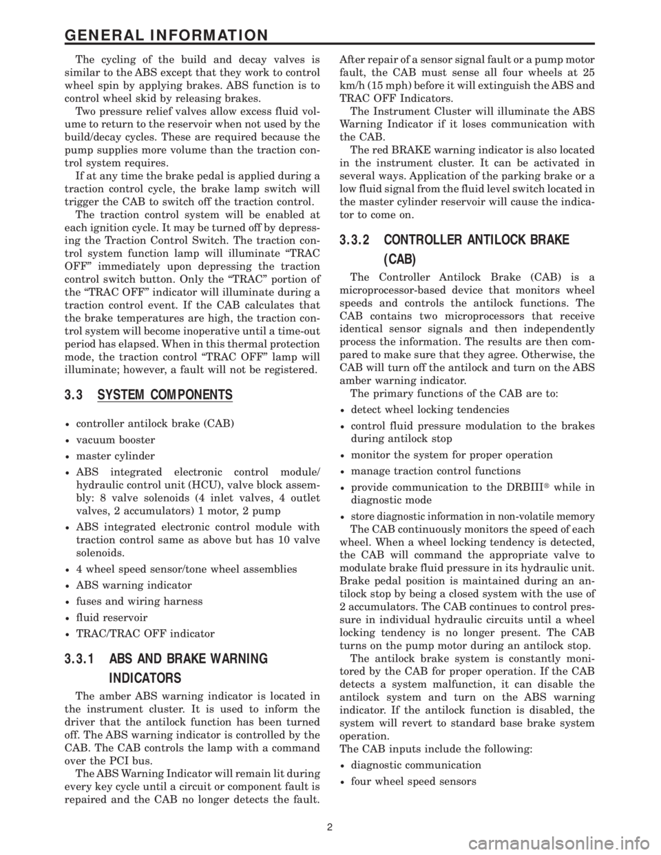
The cycling of the build and decay valves is
similar to the ABS except that they work to control
wheel spin by applying brakes. ABS function is to
control wheel skid by releasing brakes.
Two pressure relief valves allow excess fluid vol-
ume to return to the reservoir when not used by the
build/decay cycles. These are required because the
pump supplies more volume than the traction con-
trol system requires.
If at any time the brake pedal is applied during a
traction control cycle, the brake lamp switch will
trigger the CAB to switch off the traction control.
The traction control system will be enabled at
each ignition cycle. It may be turned off by depress-
ing the Traction Control Switch. The traction con-
trol system function lamp will illuminate ªTRAC
OFFº immediately upon depressing the traction
control switch button. Only the ªTRACº portion of
the ªTRAC OFFº indicator will illuminate during a
traction control event. If the CAB calculates that
the brake temperatures are high, the traction con-
trol system will become inoperative until a time-out
period has elapsed. When in this thermal protection
mode, the traction control ªTRAC OFFº lamp will
illuminate; however, a fault will not be registered.
3.3 SYSTEM COMPONENTS
²controller antilock brake (CAB)
²vacuum booster
²master cylinder
²ABS integrated electronic control module/
hydraulic control unit (HCU), valve block assem-
bly: 8 valve solenoids (4 inlet valves, 4 outlet
valves, 2 accumulators) 1 motor, 2 pump
²ABS integrated electronic control module with
traction control same as above but has 10 valve
solenoids.
²4 wheel speed sensor/tone wheel assemblies
²ABS warning indicator
²fuses and wiring harness
²fluid reservoir
²TRAC/TRAC OFF indicator
3.3.1 ABS AND BRAKE WARNING
INDICATORS
The amber ABS warning indicator is located in
the instrument cluster. It is used to inform the
driver that the antilock function has been turned
off. The ABS warning indicator is controlled by the
CAB. The CAB controls the lamp with a command
over the PCI bus.
The ABS Warning Indicator will remain lit during
every key cycle until a circuit or component fault is
repaired and the CAB no longer detects the fault.After repair of a sensor signal fault or a pump motor
fault, the CAB must sense all four wheels at 25
km/h (15 mph) before it will extinguish the ABS and
TRAC OFF Indicators.
The Instrument Cluster will illuminate the ABS
Warning Indicator if it loses communication with
the CAB.
The red BRAKE warning indicator is also located
in the instrument cluster. It can be activated in
several ways. Application of the parking brake or a
low fluid signal from the fluid level switch located in
the master cylinder reservoir will cause the indica-
tor to come on.
3.3.2 CONTROLLER ANTILOCK BRAKE
(CAB)
The Controller Antilock Brake (CAB) is a
microprocessor-based device that monitors wheel
speeds and controls the antilock functions. The
CAB contains two microprocessors that receive
identical sensor signals and then independently
process the information. The results are then com-
pared to make sure that they agree. Otherwise, the
CAB will turn off the antilock and turn on the ABS
amber warning indicator.
The primary functions of the CAB are to:
²detect wheel locking tendencies
²control fluid pressure modulation to the brakes
during antilock stop
²monitor the system for proper operation
²manage traction control functions
²provide communication to the DRBIIItwhile in
diagnostic mode
²store diagnostic information in non-volatile memory
The CAB continuously monitors the speed of each
wheel. When a wheel locking tendency is detected,
the CAB will command the appropriate valve to
modulate brake fluid pressure in its hydraulic unit.
Brake pedal position is maintained during an an-
tilock stop by being a closed system with the use of
2 accumulators. The CAB continues to control pres-
sure in individual hydraulic circuits until a wheel
locking tendency is no longer present. The CAB
turns on the pump motor during an antilock stop.
The antilock brake system is constantly moni-
tored by the CAB for proper operation. If the CAB
detects a system malfunction, it can disable the
antilock system and turn on the ABS warning
indicator. If the antilock function is disabled, the
system will revert to standard base brake system
operation.
The CAB inputs include the following:
²diagnostic communication
²four wheel speed sensors
2
GENERAL INFORMATION
Page 1419 of 4284
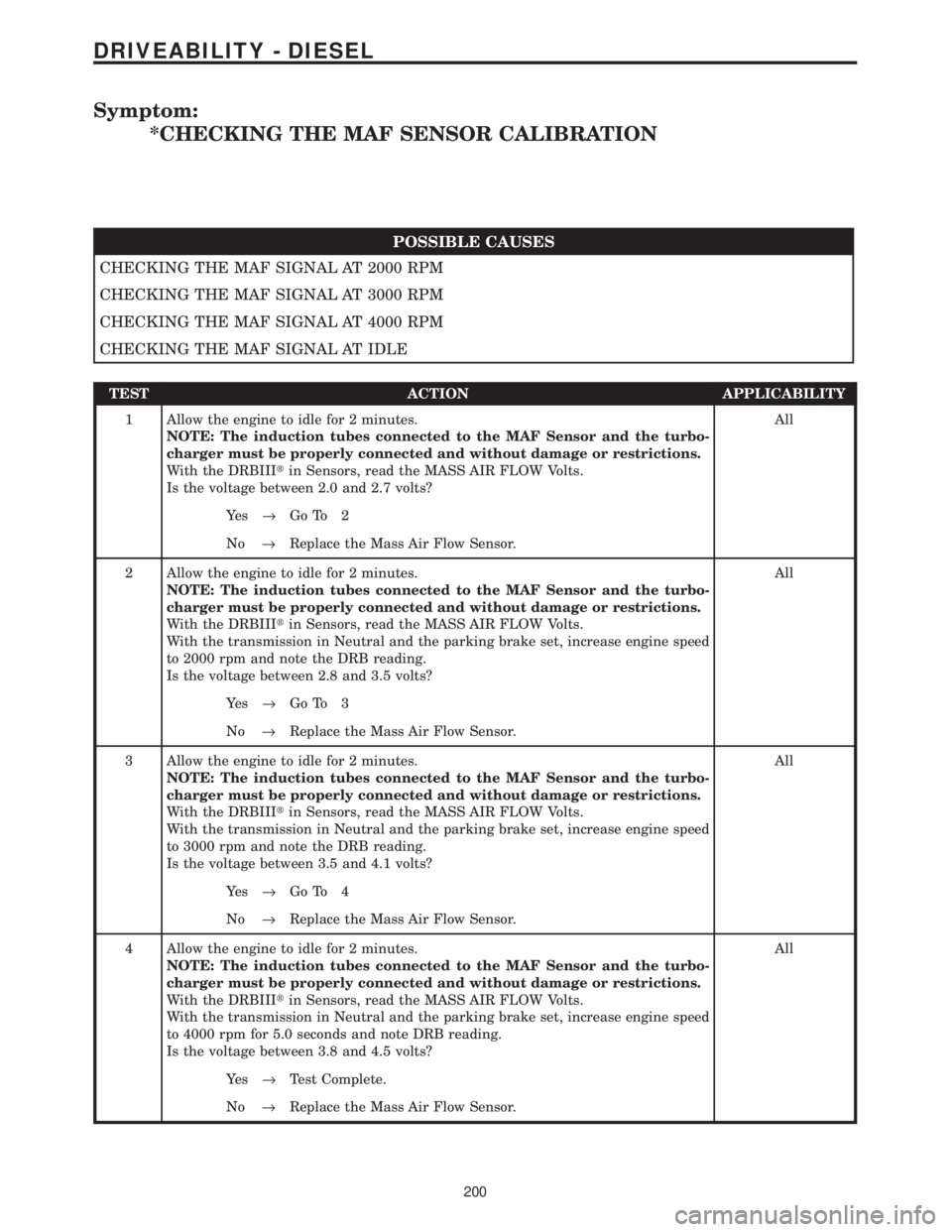
Symptom:
*CHECKING THE MAF SENSOR CALIBRATION
POSSIBLE CAUSES
CHECKING THE MAF SIGNAL AT 2000 RPM
CHECKING THE MAF SIGNAL AT 3000 RPM
CHECKING THE MAF SIGNAL AT 4000 RPM
CHECKING THE MAF SIGNAL AT IDLE
TEST ACTION APPLICABILITY
1 Allow the engine to idle for 2 minutes.
NOTE: The induction tubes connected to the MAF Sensor and the turbo-
charger must be properly connected and without damage or restrictions.
With the DRBIIItin Sensors, read the MASS AIR FLOW Volts.
Is the voltage between 2.0 and 2.7 volts?All
Ye s®Go To 2
No®Replace the Mass Air Flow Sensor.
2 Allow the engine to idle for 2 minutes.
NOTE: The induction tubes connected to the MAF Sensor and the turbo-
charger must be properly connected and without damage or restrictions.
With the DRBIIItin Sensors, read the MASS AIR FLOW Volts.
With the transmission in Neutral and the parking brake set, increase engine speed
to 2000 rpm and note the DRB reading.
Is the voltage between 2.8 and 3.5 volts?All
Ye s®Go To 3
No®Replace the Mass Air Flow Sensor.
3 Allow the engine to idle for 2 minutes.
NOTE: The induction tubes connected to the MAF Sensor and the turbo-
charger must be properly connected and without damage or restrictions.
With the DRBIIItin Sensors, read the MASS AIR FLOW Volts.
With the transmission in Neutral and the parking brake set, increase engine speed
to 3000 rpm and note the DRB reading.
Is the voltage between 3.5 and 4.1 volts?All
Ye s®Go To 4
No®Replace the Mass Air Flow Sensor.
4 Allow the engine to idle for 2 minutes.
NOTE: The induction tubes connected to the MAF Sensor and the turbo-
charger must be properly connected and without damage or restrictions.
With the DRBIIItin Sensors, read the MASS AIR FLOW Volts.
With the transmission in Neutral and the parking brake set, increase engine speed
to 4000 rpm for 5.0 seconds and note DRB reading.
Is the voltage between 3.8 and 4.5 volts?All
Ye s®Test Complete.
No®Replace the Mass Air Flow Sensor.
200
DRIVEABILITY - DIESEL
Page 1820 of 4284
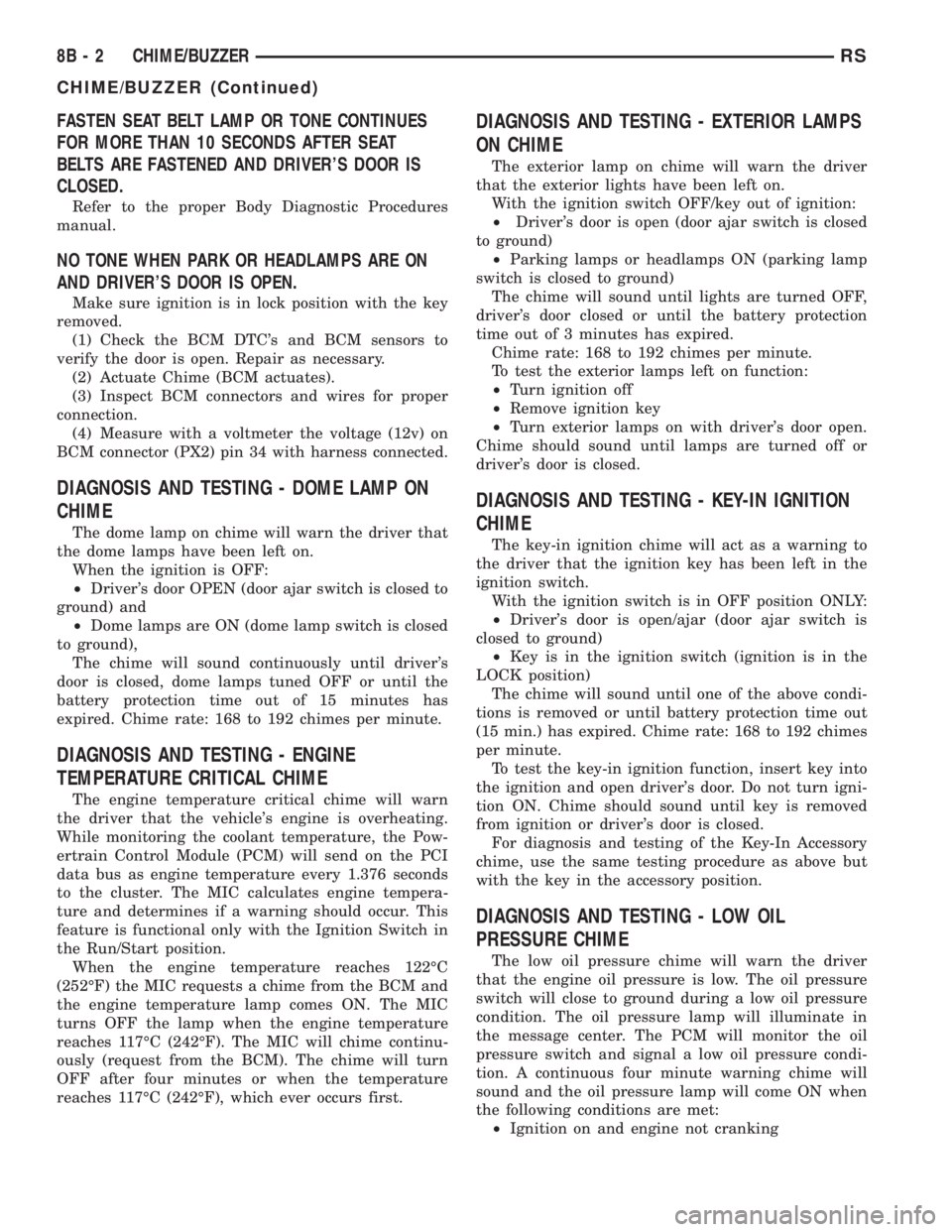
FASTEN SEAT BELT LAMP OR TONE CONTINUES
FOR MORE THAN 10 SECONDS AFTER SEAT
BELTS ARE FASTENED AND DRIVER'S DOOR IS
CLOSED.
Refer to the proper Body Diagnostic Procedures
manual.
NO TONE WHEN PARK OR HEADLAMPS ARE ON
AND DRIVER'S DOOR IS OPEN.
Make sure ignition is in lock position with the key
removed.
(1) Check the BCM DTC's and BCM sensors to
verify the door is open. Repair as necessary.
(2) Actuate Chime (BCM actuates).
(3) Inspect BCM connectors and wires for proper
connection.
(4) Measure with a voltmeter the voltage (12v) on
BCM connector (PX2) pin 34 with harness connected.
DIAGNOSIS AND TESTING - DOME LAMP ON
CHIME
The dome lamp on chime will warn the driver that
the dome lamps have been left on.
When the ignition is OFF:
²Driver's door OPEN (door ajar switch is closed to
ground) and
²Dome lamps are ON (dome lamp switch is closed
to ground),
The chime will sound continuously until driver's
door is closed, dome lamps tuned OFF or until the
battery protection time out of 15 minutes has
expired. Chime rate: 168 to 192 chimes per minute.
DIAGNOSIS AND TESTING - ENGINE
TEMPERATURE CRITICAL CHIME
The engine temperature critical chime will warn
the driver that the vehicle's engine is overheating.
While monitoring the coolant temperature, the Pow-
ertrain Control Module (PCM) will send on the PCI
data bus as engine temperature every 1.376 seconds
to the cluster. The MIC calculates engine tempera-
ture and determines if a warning should occur. This
feature is functional only with the Ignition Switch in
the Run/Start position.
When the engine temperature reaches 122ÉC
(252ÉF) the MIC requests a chime from the BCM and
the engine temperature lamp comes ON. The MIC
turns OFF the lamp when the engine temperature
reaches 117ÉC (242ÉF). The MIC will chime continu-
ously (request from the BCM). The chime will turn
OFF after four minutes or when the temperature
reaches 117ÉC (242ÉF), which ever occurs first.
DIAGNOSIS AND TESTING - EXTERIOR LAMPS
ON CHIME
The exterior lamp on chime will warn the driver
that the exterior lights have been left on.
With the ignition switch OFF/key out of ignition:
²Driver's door is open (door ajar switch is closed
to ground)
²Parking lamps or headlamps ON (parking lamp
switch is closed to ground)
The chime will sound until lights are turned OFF,
driver's door closed or until the battery protection
time out of 3 minutes has expired.
Chime rate: 168 to 192 chimes per minute.
To test the exterior lamps left on function:
²Turn ignition off
²Remove ignition key
²Turn exterior lamps on with driver's door open.
Chime should sound until lamps are turned off or
driver's door is closed.
DIAGNOSIS AND TESTING - KEY-IN IGNITION
CHIME
The key-in ignition chime will act as a warning to
the driver that the ignition key has been left in the
ignition switch.
With the ignition switch is in OFF position ONLY:
²Driver's door is open/ajar (door ajar switch is
closed to ground)
²Key is in the ignition switch (ignition is in the
LOCK position)
The chime will sound until one of the above condi-
tions is removed or until battery protection time out
(15 min.) has expired. Chime rate: 168 to 192 chimes
per minute.
To test the key-in ignition function, insert key into
the ignition and open driver's door. Do not turn igni-
tion ON. Chime should sound until key is removed
from ignition or driver's door is closed.
For diagnosis and testing of the Key-In Accessory
chime, use the same testing procedure as above but
with the key in the accessory position.
DIAGNOSIS AND TESTING - LOW OIL
PRESSURE CHIME
The low oil pressure chime will warn the driver
that the engine oil pressure is low. The oil pressure
switch will close to ground during a low oil pressure
condition. The oil pressure lamp will illuminate in
the message center. The PCM will monitor the oil
pressure switch and signal a low oil pressure condi-
tion. A continuous four minute warning chime will
sound and the oil pressure lamp will come ON when
the following conditions are met:
²Ignition on and engine not cranking
8B - 2 CHIME/BUZZERRS
CHIME/BUZZER (Continued)
Page 2100 of 4284
Component Page
Ignition Switch....................... 8Wa-10
Inlet Air Temperature Sensor............ 8Wa-30
Instrument Cluster................... 8Wa-40
Instrument Panel Switch Bank . . 8Wa-44, 52, 53, 63
Intelligent Power Module............... 8Wa-10
Knock Sensor........................ 8Wa-30
Leak Detection Pump.................. 8Wa-30
License Lamp........................ 8Wa-51
Lift Pump Motor..................... 8Wa-30
Lift Pump Relay...................... 8Wa-30
Liftgate Ajar Switch................... 8Wa-61
Liftgate Cinch/Release Motor............ 8Wa-61
Liftgate Cylinder Lock Switch........... 8Wa-39
Liftgate Flood Lamps.................. 8Wa-44
Liftgate Left Pinch Sensor.............. 8Wa-61
Low Beam Lamps.................... 8Wa-50
Manifold Absolute Pressure Sensor....... 8Wa-30
Mass Air Flow Sensor................. 8Wa-30
Memory Power Seat Switch............. 8Wa-63
Memory Seat Front Vertical Motor........ 8Wa-63
Memory Seat Front Vertical Position
Sensor........................... 8Wa-63
Memory Seat Horizontal Motor.......... 8Wa-63
Memory Seat Horizontal Position Sensor . . . 8Wa-63
Memory Seat Rear Vertical Motor........ 8Wa-63
Memory Seat Rear Vertical Position
Sensor........................... 8Wa-63
Memory Seat Recliner Motor............ 8Wa-63
Memory Seat Recliner Position Sensor..... 8Wa-63
Memory Seat Switch.................. 8Wa-63
Memory Seat/Mirror Module............ 8Wa-62
Message Center...................... 8Wa-46
Mode Door Actuator................... 8Wa-42
Multi- Function Switch................ 8Wa-50
Name Brand Speaker Relay............. 8Wa-47
Occupant Restraint Controller........... 8Wa-43
Overhead Console.................... 8Wa-49
Oxygen Sensors...................... 8Wa-30
Park Lamp Relay..................... 8Wa-10
Park Lamps......................... 8Wa-50
Park/Neutral Position Switch............ 8Wa-31
Park/Turn Signal Lamps............... 8Wa-50
Parking Brake Switch................. 8Wa-40
Passenger Folding Mirror Relay.......... 8Wa-62
Power Folding Mirror Switch............ 8Wa-62
Power Liftgate Motor.................. 8Wa-61
Power Mirror Switch.................. 8Wa-62
Power Mirrors....................... 8Wa-62
Power Outlets....................... 8Wa-41
Power Seat Circuit Breaker............. 8Wa-10
Power Seat Front Riser Motors.......... 8Wa-63
Power Seat Horizontal Motors........... 8Wa-63
Power Seat Rear Riser Motors........... 8Wa-63
Power Seat Recliner Motors............. 8Wa-63Component Page
Power Seat Switches.................. 8Wa-63
Power Window Circuit Breaker.......... 8Wa-10
Power Window Motors................. 8Wa-60
Power Window Switches................ 8Wa-60
Powertrain Control Module............. 8Wa-30
PTC ............................... 8Wa-10
Radiator Fan Relays.................. 8Wa-42
Radiator Fans....................... 8Wa-42
Radio Choke......................... 8Wa-47
Radio.............................. 8Wa-47
Reading Lamps...................... 8Wa-44
Rear A/C-Heater Unit................. 8Wa-42
Rear Auto Temp Control Switch.......... 8Wa-42
Rear Blower Front Control Switch........ 8Wa-42
Rear Blower Motor Power Module........ 8Wa-42
Rear Blower Motor Relay............... 8Wa-42
Rear Blower Motor.................... 8Wa-42
Rear Blower Rear Control Switch........ 8Wa-42
Rear Intrusion Sensor................. 8Wa-39
Rear Lamp Assemblies................. 8Wa-51
Rear Mode Motor..................... 8Wa-42
Rear Temperature Motor............... 8Wa-42
Rear Washer Pump Motor.............. 8Wa-53
Rear Window Defogger Grid............. 8Wa-48
Rear Wiper Motor.................... 8Wa-53
Recirculation Door Actuator............. 8Wa-42
Remote Keyless Entry Antenna.......... 8Wa-61
Remote Keyless Entry Module........... 8Wa-61
Remote Radio Switches................ 8Wa-47
Repeater Lamps...................... 8Wa-52
Seat Airbags......................... 8Wa-43
Seat Belt Switches.................... 8Wa-43
Seat Belt Tensioners.................. 8Wa-43
Sentry Key Immobilizer Module.......... 8Wa-39
Side Impact Airbag Control Module....... 8Wa-43
Siren.............................. 8Wa-39
Sliding Door Control Modules........... 8Wa-61
Sliding Door Latch Sensing Switches...... 8Wa-61
Sliding Door Lock Motor/Ajar Switches.... 8Wa-61
Sliding Door Lock Motors............... 8Wa-61
Sliding Door Motors................... 8Wa-61
Solenoid/Pressure Switch Assy........... 8Wa-31
Speakers........................... 8Wa-47
Speed Control Servo................... 8Wa-33
Speed Control Switches................ 8Wa-33
Speed Sensor- Input................... 8Wa-31
Speed Sensor- Output................. 8Wa-31
Splice Information.................... 8Wa-70
Starter Motor Relay................... 8Wa-21
Starter Motor........................ 8Wa-21
Stop/Turn Signal Relays................ 8Wa-54
Thatcham Alarm Indicator.............. 8Wa-39
Thatcham Alarm Module............... 8Wa-39
Throttle Position Sensor................ 8Wa-30
8Wa - 02 - 2 8W-02 COMPONENT INDEXRG
Page 3210 of 4284
FLUID
STANDARD PROCEDURE - FLUID LEVEL AND
CONDITION CHECK
NOTE: Only transmission fluid of the type labeled
Mopar ATF+4 (Automatic Transmission Fluid±Type
9602) should be used in this transaxle.
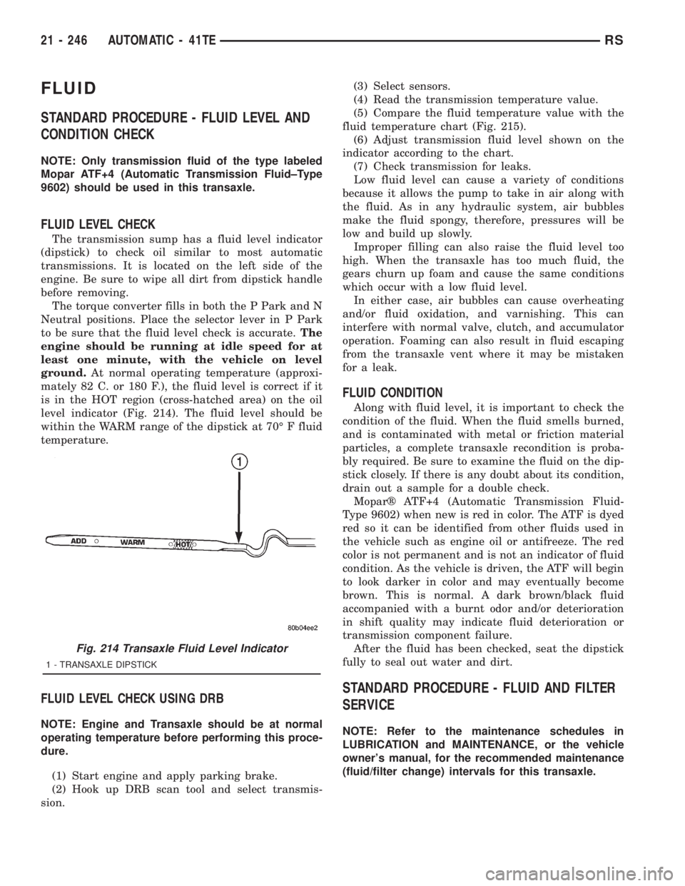
FLUID LEVEL CHECK
The transmission sump has a fluid level indicator
(dipstick) to check oil similar to most automatic
transmissions. It is located on the left side of the
engine. Be sure to wipe all dirt from dipstick handle
before removing.
The torque converter fills in both the P Park and N
Neutral positions. Place the selector lever in P Park
to be sure that the fluid level check is accurate.The
engine should be running at idle speed for at
least one minute, with the vehicle on level
ground.At normal operating temperature (approxi-
mately 82 C. or 180 F.), the fluid level is correct if it
is in the HOT region (cross-hatched area) on the oil
level indicator (Fig. 214). The fluid level should be
within the WARM range of the dipstick at 70É F fluid
temperature.
FLUID LEVEL CHECK USING DRB
NOTE: Engine and Transaxle should be at normal
operating temperature before performing this proce-
dure.
(1) Start engine and apply parking brake.
(2) Hook up DRB scan tool and select transmis-
sion.(3) Select sensors.
(4) Read the transmission temperature value.
(5) Compare the fluid temperature value with the
fluid temperature chart (Fig. 215).
(6) Adjust transmission fluid level shown on the
indicator according to the chart.
(7) Check transmission for leaks.
Low fluid level can cause a variety of conditions
because it allows the pump to take in air along with
the fluid. As in any hydraulic system, air bubbles
make the fluid spongy, therefore, pressures will be
low and build up slowly.
Improper filling can also raise the fluid level too
high. When the transaxle has too much fluid, the
gears churn up foam and cause the same conditions
which occur with a low fluid level.
In either case, air bubbles can cause overheating
and/or fluid oxidation, and varnishing. This can
interfere with normal valve, clutch, and accumulator
operation. Foaming can also result in fluid escaping
from the transaxle vent where it may be mistaken
for a leak.
FLUID CONDITION
Along with fluid level, it is important to check the
condition of the fluid. When the fluid smells burned,
and is contaminated with metal or friction material
particles, a complete transaxle recondition is proba-
bly required. Be sure to examine the fluid on the dip-
stick closely. If there is any doubt about its condition,
drain out a sample for a double check.
Moparž ATF+4 (Automatic Transmission Fluid-
Type 9602) when new is red in color. The ATF is dyed
red so it can be identified from other fluids used in
the vehicle such as engine oil or antifreeze. The red
color is not permanent and is not an indicator of fluid
condition. As the vehicle is driven, the ATF will begin
to look darker in color and may eventually become
brown. This is normal. A dark brown/black fluid
accompanied with a burnt odor and/or deterioration
in shift quality may indicate fluid deterioration or
transmission component failure.
After the fluid has been checked, seat the dipstick
fully to seal out water and dirt.
STANDARD PROCEDURE - FLUID AND FILTER
SERVICE
NOTE: Refer to the maintenance schedules in
LUBRICATION and MAINTENANCE, or the vehicle
owner's manual, for the recommended maintenance
(fluid/filter change) intervals for this transaxle.
Fig. 214 Transaxle Fluid Level Indicator
1 - TRANSAXLE DIPSTICK
21 - 246 AUTOMATIC - 41TERS