2001 CHRYSLER VOYAGER alternator
[x] Cancel search: alternatorPage 3806 of 4284

When testing voltage or continuity at any control
module, use the terminal side (not the wire end) of
the connector. Do not probe a wire through the
insulation; this will damage it and eventually cause
it to fail because of corrosion.
Be careful when performing electrical tests so as
to prevent accidental shorting of terminals. Such
mistakes can damage fuses or components. Also, a
second DTC could be set, making diagnosis of the
original problem more difficult.
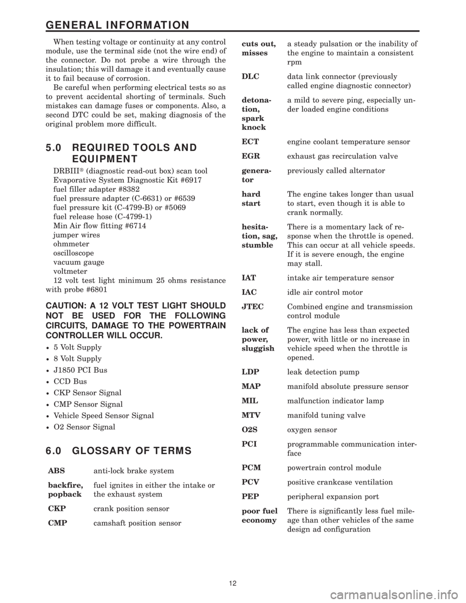
5.0 REQUIRED TOOLS AND
EQUIPMENT
DRBIIIt(diagnostic read-out box) scan tool
Evaporative System Diagnostic Kit #6917
fuel filler adapter #8382
fuel pressure adapter (C-6631) or #6539
fuel pressure kit (C-4799-B) or #5069
fuel release hose (C-4799-1)
Min Air flow fitting #6714
jumper wires
ohmmeter
oscilloscope
vacuum gauge
voltmeter
12 volt test light minimum 25 ohms resistance
with probe #6801
CAUTION: A 12 VOLT TEST LIGHT SHOULD
NOT BE USED FOR THE FOLLOWING
CIRCUITS, DAMAGE TO THE POWERTRAIN
CONTROLLER WILL OCCUR.
²5 Volt Supply
²8 Volt Supply
²J1850 PCI Bus
²CCD Bus
²CKP Sensor Signal
²CMP Sensor Signal
²Vehicle Speed Sensor Signal
²O2 Sensor Signal
6.0 GLOSSARY OF TERMS
ABSanti-lock brake system
backfire,
popbackfuel ignites in either the intake or
the exhaust system
CKPcrank position sensor
CMPcamshaft position sensorcuts out,
missesa steady pulsation or the inability of
the engine to maintain a consistent
rpm
DLCdata link connector (previously
called engine diagnostic connector)
detona-
tion,
spark
knocka mild to severe ping, especially un-
der loaded engine conditions
ECTengine coolant temperature sensor
EGRexhaust gas recirculation valve
genera-
torpreviously called alternator
hard
startThe engine takes longer than usual
to start, even though it is able to
crank normally.
hesita-
tion, sag,
stumbleThere is a momentary lack of re-
sponse when the throttle is opened.
This can occur at all vehicle speeds.
If it is severe enough, the engine
may stall.
IATintake air temperature sensor
IACidle air control motor
JTECCombined engine and transmission
control module
lack of
power,
sluggishThe engine has less than expected
power, with little or no increase in
vehicle speed when the throttle is
opened.
LDPleak detection pump
MAPmanifold absolute pressure sensor
MILmalfunction indicator lamp
MTVmanifold tuning valve
O2Soxygen sensor
PCIprogrammable communication inter-
face
PCMpowertrain control module
PCVpositive crankcase ventilation
PEPperipheral expansion port
poor fuel
economyThere is significantly less fuel mile-
age than other vehicles of the same
design ad configuration
12
GENERAL INFORMATION
Page 4120 of 4284

since there is no power available to control the
transmission solenoids. However if power is re-
stored, the TCM will power-up and normal opera-
tion will be restored. This DTC identifies that
power to the TCM was restored when the gear
selector was in a9Drive9position while the vehicle
was moving at speeds above 32 Km/h (20 MPH). If
a person shifts to Neutral and cycles the ignition
key and quickly shifts to9Drive9while moving
before the TCM comes out of its START ROUTINE,
the DTC can be set. Therefore it is critical that this
DTC diagnosis repair procedure should only be used
if the vehicle is experiencing intermittent 2nd gear
operation and subsequently a return to normal
operation during normal driving.
Transmission Effects:No limp-in condition. The
DTC is for information only when trying to diagno-
sis intermittent 2nd gear operation and subse-
quently a return to normal operation.
Possible Causes:
± No Problem if vehicle is started in9neutral9at
speeds above 32 Km/h (20 MPH) and shifted
quickly to9Drive9before TCM comes out of the
START ROUTINE.
FOR INTERMITTENT 2ND GEAR OPER-
ATION AND THEN A SUBSEQUENT RE-
TURN TO NORMAL OPERATION WITH-
OUT CYCLING THE IGNITION KEY
± Intermittent Direct Battery connection be-
tween TCM (60-way pin 56) and battery.
± Intermittent Fused Ignition Switch Output
between TCM (60-way pin 11) and ignition
switch.
± Intermittent Ground to TCM (60 way pins 53
and 57).
Name of code:P1717(77) - No Communication
with Mechanical Instrument Cluster (MIC)
When monitored:Continuously with key on.
Set condition:If no PCI bus messages are received
from the Mechanical Instrument Cluster (MIC) for
25 seconds.
Theory of operation:The TCM communicates
with the MIC using the PCI bus. It relies on certain
information to function properly. The TCM contin-
uously monitors the PCI bus to check for messages
broadcast from the PCM.
Transmission Effects:Possible improper TCM
AutoStick configuration.
Possible causes:
> Open or shorted PCI bus circuit from MIC
> MIC
> TCM (If other communications codes are stored
in the TCM only)
Name of code:P0600(78) - Serial Communication
Link Malfunction
When monitored:Continuously with key on.
Set condition:If no PCI bus messages are received
by the Transmission Control Module (TCM) for 10
seconds.
Theory of operation:The TCM communicates
with the other modules in the vehicle using the PCI
bus. It relies on certain information to function
properly. The TCM continuously monitors the PCI
bus to check for messages broadcast from the cer-
tain modules.
Transmission Effects:Possible improper TCM
AutoStick configuration and delayed 3-4 shifts. No
EMCC and early 3-4 shifts for a few minutes after
engine is started.
Possible causes:
> Open or shorted PCI bus circuit from BCM
> TCM
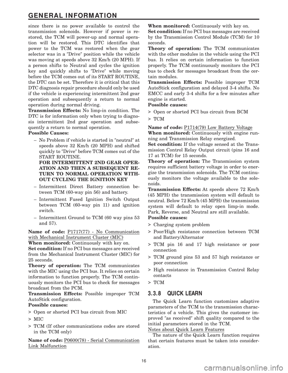
Name of code:P1714(79) Low Battery Voltage
When monitored:Continuously with engine run-
ning and Transmission Relay energized.
Set condition:If the voltage sensed at the Trans-
mission Control Relay Output circuit (pins 16 and
17 at TCM) for 15 seconds.
Theory of operation:The Transmission system
requires sufficient battery voltage in order to ener-
gize the transmission solenoids. The TCM continu-
ously monitors the voltage available to the sole-
noids.
Transmission Effects:At speeds above 72 Km/h
(45 MPH) the transmission system will default to
neutral. Below 72 Km/h (45 MPH) the transmission
system will default to relay open limp-in mode.
Park, Reverse, and Neutral are still available.
Possible causes:
> Charging system problem
> Poor/High resistance connection between TCM
and Battery/Alternator
> TCM pin 16 and 17 high resistance or poor
connection
> TCM ground pins 53 and 57 high resistance or
poor connection
> High resistance in Transmission Control Relay
contacts
> TCM
3.3.8 QUICK LEARN
The Quick Learn function customizes adaptive
parameters of the TCM to the transmission charac-
teristics of a vehicle. This gives the customer im-
proved9as received9shift quality compared to the
initial parameters stored in the TCM.
Notes about Quick Learn Features
The nature of the Quick Learn function requires
that certain features must be taken into consider-
ation.
16
GENERAL INFORMATION
Page 4258 of 4284

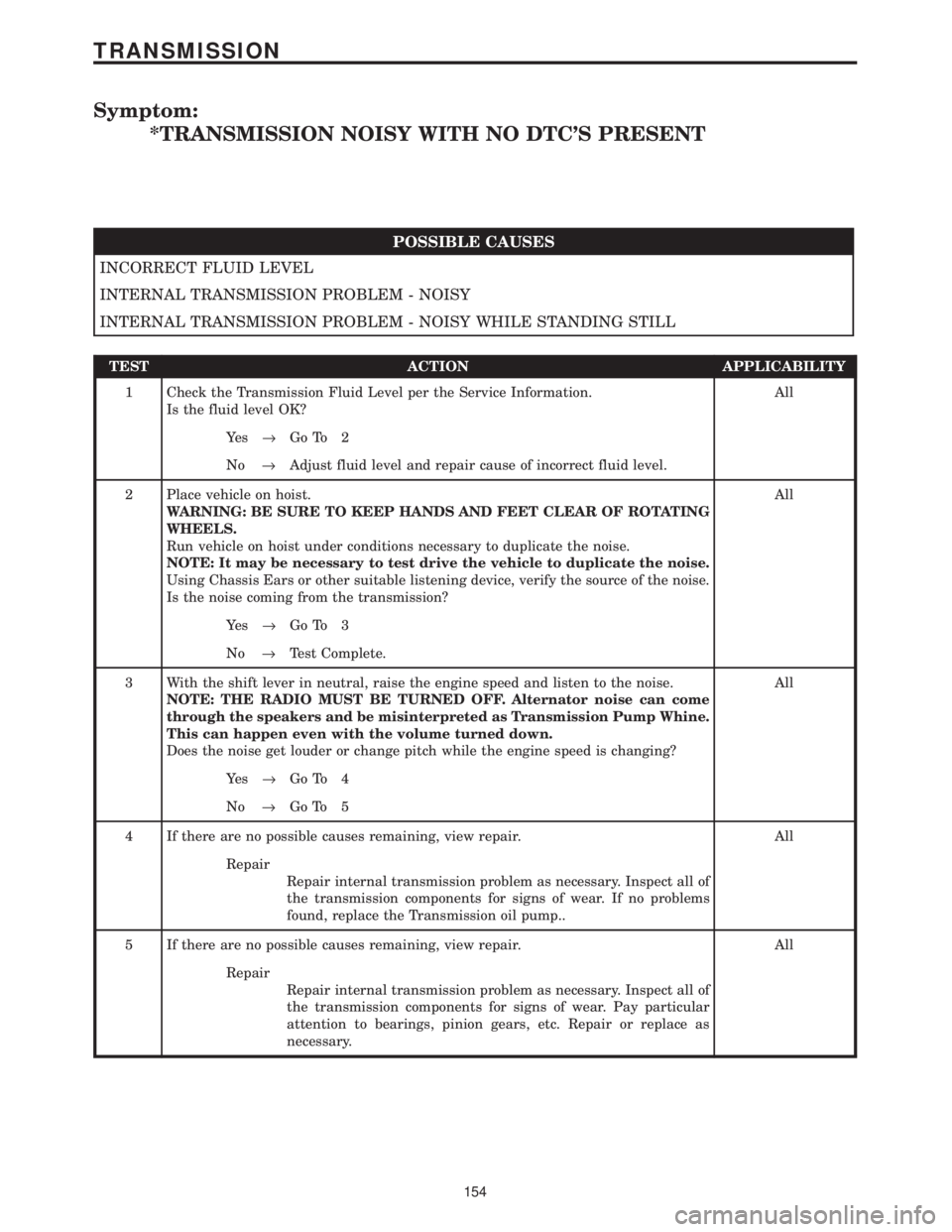
Symptom:
*TRANSMISSION NOISY WITH NO DTC'S PRESENT
POSSIBLE CAUSES
INCORRECT FLUID LEVEL
INTERNAL TRANSMISSION PROBLEM - NOISY
INTERNAL TRANSMISSION PROBLEM - NOISY WHILE STANDING STILL
TEST ACTION APPLICABILITY
1 Check the Transmission Fluid Level per the Service Information.
Is the fluid level OK?All
Ye s®Go To 2
No®Adjust fluid level and repair cause of incorrect fluid level.
2 Place vehicle on hoist.
WARNING: BE SURE TO KEEP HANDS AND FEET CLEAR OF ROTATING
WHEELS.
Run vehicle on hoist under conditions necessary to duplicate the noise.
NOTE: It may be necessary to test drive the vehicle to duplicate the noise.
Using Chassis Ears or other suitable listening device, verify the source of the noise.
Is the noise coming from the transmission?All
Ye s®Go To 3
No®Test Complete.
3 With the shift lever in neutral, raise the engine speed and listen to the noise.
NOTE: THE RADIO MUST BE TURNED OFF. Alternator noise can come
through the speakers and be misinterpreted as Transmission Pump Whine.
This can happen even with the volume turned down.
Does the noise get louder or change pitch while the engine speed is changing?All
Ye s®Go To 4
No®Go To 5
4 If there are no possible causes remaining, view repair. All
Repair
Repair internal transmission problem as necessary. Inspect all of
the transmission components for signs of wear. If no problems
found, replace the Transmission oil pump..
5 If there are no possible causes remaining, view repair. All
Repair
Repair internal transmission problem as necessary. Inspect all of
the transmission components for signs of wear. Pay particular
attention to bearings, pinion gears, etc. Repair or replace as
necessary.
154
TRANSMISSION