2001 CHRYSLER VOYAGER adding oil
[x] Cancel search: adding oilPage 1735 of 4284

COOLING
TABLE OF CONTENTS
page page
COOLING
DESCRIPTION............................1
OPERATION.............................1
DIAGNOSIS AND TESTING..................3
COOLING SYSTEM LEAK TEST.............3
COOLING SYSTEM FLOW CHECK..........3
COOLING SYSTEM AERATION.............3
COOLING SYSTEM DEAERATION...........3
STANDARD PROCEDURE...................4COOLING SYSTEM - DRAINING............4
COOLING SYSTEM - REFILLING............4
COOLANT - ADDING ADDITIONAL...........4
COOLANT LEVEL CHECK - ROUTINE........5
SPECIFICATIONS.........................6
SPECIAL TOOLS..........................6
ACCESSORY DRIVE.......................7
ENGINE................................13
TRANSMISSION.........................36
COOLING
DESCRIPTION - COOLING SYSTEM
The cooling system components consist of a radia-
tor, electric fan motors, shroud, pressure cap, thermo-
stat, transmission oil cooler, water pump, hoses,
clamps, coolant, and a coolant reserve system to com-
plete the circuit.
DESCRIPTION - HOSE CLAMPS
The cooling system uses spring type hose clamps.
If a spring type clamp replacement is necessary,
replace with the original Mopartequipment spring
type clamp.
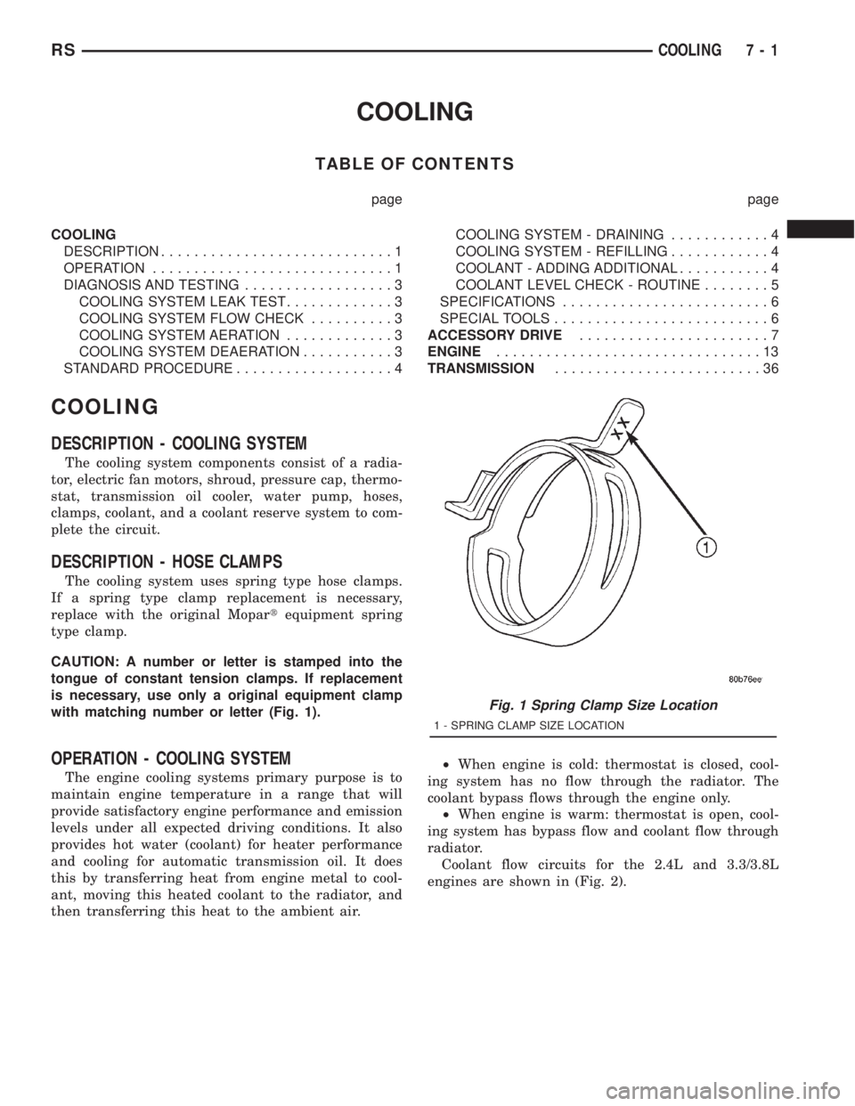
CAUTION: A number or letter is stamped into the
tongue of constant tension clamps. If replacement
is necessary, use only a original equipment clamp
with matching number or letter (Fig. 1).
OPERATION - COOLING SYSTEM
The engine cooling systems primary purpose is to
maintain engine temperature in a range that will
provide satisfactory engine performance and emission
levels under all expected driving conditions. It also
provides hot water (coolant) for heater performance
and cooling for automatic transmission oil. It does
this by transferring heat from engine metal to cool-
ant, moving this heated coolant to the radiator, and
then transferring this heat to the ambient air.²When engine is cold: thermostat is closed, cool-
ing system has no flow through the radiator. The
coolant bypass flows through the engine only.
²When engine is warm: thermostat is open, cool-
ing system has bypass flow and coolant flow through
radiator.
Coolant flow circuits for the 2.4L and 3.3/3.8L
engines are shown in (Fig. 2).
Fig. 1 Spring Clamp Size Location
1 - SPRING CLAMP SIZE LOCATION
RSCOOLING7-1
Page 1789 of 4284

100 Percent Ethylene-GlycolÐShould Not Be Used in
Chrysler Vehicles
Use of 100 percent ethylene-glycol will cause for-
mation of additive deposits in the system, as the cor-
rosion inhibitive additives in ethylene-glycol require
the presence of water to dissolve. The deposits act as
insulation, causing temperatures to rise to as high as
149 deg. C (300 deg. F). This temperature is hot
enough to melt plastic and soften solder. The
increased temperature can result in engine detona-
tion. In addition, 100 percent ethylene-glycol freezes
at -22 deg. C (-8 deg. F ).
Propylene-glycol FormulationsÐShould Not Be Used in
Chrysler Vehicles
Propylene-glycol formulations do not meet
Chrysler coolant specifications.It's overall effec-
tive temperature range is smaller than that of ethyl-
ene-glycol. The freeze point of 50/50 propylene-glycol
and water is -32 deg. C (-26 deg. F). 5 deg. C higher
than ethylene-glycol's freeze point. The boiling point
(protection against summer boil-over) of propylene-
glycol is 125 deg. C (257 deg.F)at96.5 kPa (14 psi),
compared to 128 deg. C (263 deg. F) for ethylene-gly-
col. Use of propylene-glycol can result in boil-over or
freeze-up in Chrysler vehicles, which are designed for
ethylene-glycol. Propylene glycol also has poorer heat
transfer characteristics than ethylene glycol. This
can increase cylinder head temperatures under cer-
tain conditions.
Propylene-glycol/Ethylene-glycol MixturesÐShould Not Be
Used in Chrysler Vehicles
Propylene-glycol/ethylene-glycol Mixtures can
cause the destabilization of various corrosion inhibi-
tors, causing damage to the various cooling system
components. Also, once ethylene-glycol and propy-
lene-glycol based coolants are mixed in the vehicle,
conventional methods of determining freeze point will
not be accurate. Both the refractive index and spe-
cific gravity differ between ethylene glycol and propy-
lene glycol.
CAUTION: Richer antifreeze mixtures cannot be
measured with normal field equipment and can
cause problems associated with 100 percent ethyl-
ene-glycol.DIAGNOSIS AND TESTING - COOLANT
CONCENTRATION TESTING
Coolant concentration should be checked when any
additional coolant was added to system or after a
coolant drain, flush and refill. The coolant mixture
offers optimum engine cooling and protection against
corrosion when mixed to a freeze point of -37ÉC
(-34ÉF) to -59ÉC (-50ÉF). The use of a hydrometer or a
refractometer can be used to test coolant concentra-
tion.
A hydrometer will test the amount of glycol in a
mixture by measuring the specific gravity of the mix-
ture. The higher the concentration of ethylene glycol,
the larger the number of balls that will float, and
higher the freeze protection (up to a maximum of
60% by volume glycol).
A refractometer will test the amount of glycol in a
coolant mixture by measuring the amount a beam of
light bends as it passes through the fluid.
Some coolant manufactures use other types of gly-
cols into their coolant formulations. Propylene glycol
is the most common new coolant. However, propylene
glycol based coolants do not provide the same freez-
ing protection and corrosion protection and is not rec-
ommended.
CAUTION: Do not mix types of coolantÐcorrosion
protection will be severely reduced.
STANDARD PROCEDURE - COOLANT SERVICE
For engine coolant recommended service schedule,
(Refer to LUBRICATION & MAINTENANCE/MAIN-
TENANCE SCHEDULES - DESCRIPTION).
STANDARD PROCEDURE - ADDING
ADDITIONAL COOLANT
The pressure/vent cap should not be removed
from the coolant recovery pressure container.
When additional coolant is needed to maintain this
level, it should be added to the coolant recovery pres-
sure container (Fig. 1). Use only 50/50 mix of ethyl-
ene glycol type antifreeze and distilled water. For the
recommeded antifreeze/coolant type (Refer to LUBRI-
CATION & MAINTENANCE/FLUID TYPES -
DESCRIPTION).
CAUTION: Do not use well water, or suspect water
supply in cooling system. A 50/50 ethylene glycol
and distilled water mix is recommended. For the
recommeded antifreeze/coolant type (Refer to
LUBRICATION & MAINTENANCE/FLUID TYPES -
DESCRIPTION).
RGENGINE7a-15
COOLANT (Continued)
Page 2969 of 4284

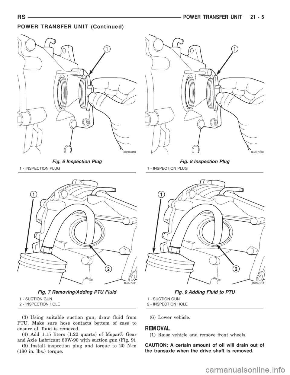
(3) Using suitable suction gun, draw fluid from
PTU. Make sure hose contacts bottom of case to
ensure all fluid is removed.
(4) Add 1.15 liters (1.22 quarts) of Moparž Gear
and Axle Lubricant 80W-90 with suction gun (Fig. 9).
(5) Install inspection plug and torque to 20 N´m
(180 in. lbs.) torque.(6) Lower vehicle.
REMOVAL
(1) Raise vehicle and remove front wheels.
CAUTION: A certain amount of oil will drain out of
the transaxle when the drive shaft is removed.
Fig. 6 Inspection Plug
1 - INSPECTION PLUG
Fig. 7 Removing/Adding PTU Fluid
1 - SUCTION GUN
2 - INSPECTION HOLE
Fig. 8 Inspection Plug
1 - INSPECTION PLUG
Fig. 9 Adding Fluid to PTU
1 - SUCTION GUN
2 - INSPECTION HOLE
RSPOWER TRANSFER UNIT21-5
POWER TRANSFER UNIT (Continued)
Page 3233 of 4284

OIL PUMP
DESCRIPTION
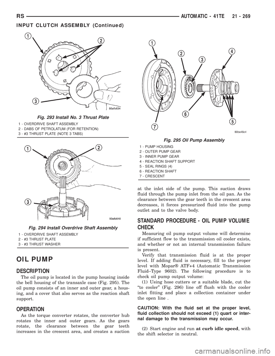
The oil pump is located in the pump housing inside
the bell housing of the transaxle case (Fig. 295). The
oil pump consists of an inner and outer gear, a hous-
ing, and a cover that also serves as the reaction shaft
support.
OPERATION
As the torque converter rotates, the converter hub
rotates the inner and outer gears. As the gears
rotate, the clearance between the gear teeth
increases in the crescent area, and creates a suctionat the inlet side of the pump. This suction draws
fluid through the pump inlet from the oil pan. As the
clearance between the gear teeth in the crescent area
decreases, it forces pressurized fluid into the pump
outlet and to the valve body.
STANDARD PROCEDURE - OIL PUMP VOLUME
CHECK
Measuring oil pump output volume will determine
if sufficient flow to the transmission oil cooler exists,
and whether or not an internal transmission failure
is present.
Verify that transmission fluid is at the proper
level. If adding fluid is necessary, fill to the proper
level with Moparž ATF+4 (Automatic Transmission
Fluid±Type 9602). The following procedure is to
check oil pump output volume:
(1) Using hose cutters or a suitable blade, cut the
ªto coolerº (Fig. 296) line off flush with the cooler
inlet fitting and place a collection container under
the open line .
CAUTION: With the fluid set at the proper level,
fluid collection should not exceed (1) quart or inter-
nal damage to the transmission may occur.
(2) Start engine and runat curb idle speed, with
the shift selector in neutral.
Fig. 293 Install No. 3 Thrust Plate
1 - OVERDRIVE SHAFT ASSEMBLY
2 - DABS OF PETROLATUM (FOR RETENTION)
3 - #3 THRUST PLATE (NOTE 3 TABS)
Fig. 294 Install Overdrive Shaft Assembly
1 - OVERDRIVE SHAFT ASSEMBLY
2 - #3 THRUST PLATE
3 - #3 THRUST WASHER
Fig. 295 Oil Pump Assembly
1 - PUMP HOUSING
2 - OUTER PUMP GEAR
3 - INNER PUMP GEAR
4 - REACTION SHAFT SUPPORT
5 - SEAL RINGS (4)
6 - REACTION SHAFT
7 - CRESCENT
RSAUTOMATIC - 41TE21 - 269
INPUT CLUTCH ASSEMBLY (Continued)