2001 CHRYSLER VOYAGER catalytic converter
[x] Cancel search: catalytic converterPage 1493 of 4284
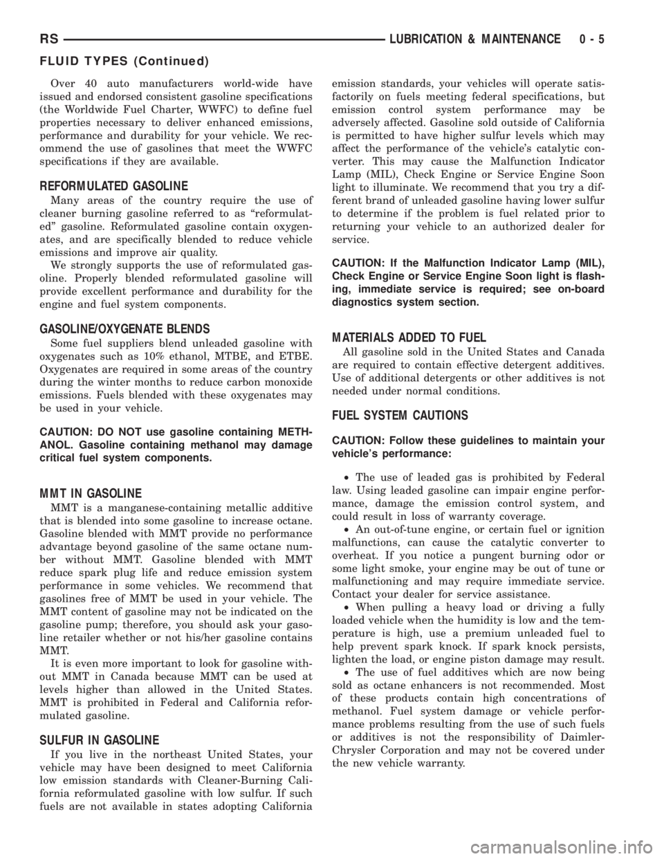
Over 40 auto manufacturers world-wide have
issued and endorsed consistent gasoline specifications
(the Worldwide Fuel Charter, WWFC) to define fuel
properties necessary to deliver enhanced emissions,
performance and durability for your vehicle. We rec-
ommend the use of gasolines that meet the WWFC
specifications if they are available.
REFORMULATED GASOLINE
Many areas of the country require the use of
cleaner burning gasoline referred to as ªreformulat-
edº gasoline. Reformulated gasoline contain oxygen-
ates, and are specifically blended to reduce vehicle
emissions and improve air quality.
We strongly supports the use of reformulated gas-
oline. Properly blended reformulated gasoline will
provide excellent performance and durability for the
engine and fuel system components.
GASOLINE/OXYGENATE BLENDS
Some fuel suppliers blend unleaded gasoline with
oxygenates such as 10% ethanol, MTBE, and ETBE.
Oxygenates are required in some areas of the country
during the winter months to reduce carbon monoxide
emissions. Fuels blended with these oxygenates may
be used in your vehicle.
CAUTION: DO NOT use gasoline containing METH-
ANOL. Gasoline containing methanol may damage
critical fuel system components.
MMT IN GASOLINE
MMT is a manganese-containing metallic additive
that is blended into some gasoline to increase octane.
Gasoline blended with MMT provide no performance
advantage beyond gasoline of the same octane num-
ber without MMT. Gasoline blended with MMT
reduce spark plug life and reduce emission system
performance in some vehicles. We recommend that
gasolines free of MMT be used in your vehicle. The
MMT content of gasoline may not be indicated on the
gasoline pump; therefore, you should ask your gaso-
line retailer whether or not his/her gasoline contains
MMT.
It is even more important to look for gasoline with-
out MMT in Canada because MMT can be used at
levels higher than allowed in the United States.
MMT is prohibited in Federal and California refor-
mulated gasoline.
SULFUR IN GASOLINE
If you live in the northeast United States, your
vehicle may have been designed to meet California
low emission standards with Cleaner-Burning Cali-
fornia reformulated gasoline with low sulfur. If such
fuels are not available in states adopting Californiaemission standards, your vehicles will operate satis-
factorily on fuels meeting federal specifications, but
emission control system performance may be
adversely affected. Gasoline sold outside of California
is permitted to have higher sulfur levels which may
affect the performance of the vehicle's catalytic con-
verter. This may cause the Malfunction Indicator
Lamp (MIL), Check Engine or Service Engine Soon
light to illuminate. We recommend that you try a dif-
ferent brand of unleaded gasoline having lower sulfur
to determine if the problem is fuel related prior to
returning your vehicle to an authorized dealer for
service.
CAUTION: If the Malfunction Indicator Lamp (MIL),
Check Engine or Service Engine Soon light is flash-
ing, immediate service is required; see on-board
diagnostics system section.
MATERIALS ADDED TO FUEL
All gasoline sold in the United States and Canada
are required to contain effective detergent additives.
Use of additional detergents or other additives is not
needed under normal conditions.
FUEL SYSTEM CAUTIONS
CAUTION: Follow these guidelines to maintain your
vehicle's performance:
²The use of leaded gas is prohibited by Federal
law. Using leaded gasoline can impair engine perfor-
mance, damage the emission control system, and
could result in loss of warranty coverage.
²An out-of-tune engine, or certain fuel or ignition
malfunctions, can cause the catalytic converter to
overheat. If you notice a pungent burning odor or
some light smoke, your engine may be out of tune or
malfunctioning and may require immediate service.
Contact your dealer for service assistance.
²When pulling a heavy load or driving a fully
loaded vehicle when the humidity is low and the tem-
perature is high, use a premium unleaded fuel to
help prevent spark knock. If spark knock persists,
lighten the load, or engine piston damage may result.
²The use of fuel additives which are now being
sold as octane enhancers is not recommended. Most
of these products contain high concentrations of
methanol. Fuel system damage or vehicle perfor-
mance problems resulting from the use of such fuels
or additives is not the responsibility of Daimler-
Chrysler Corporation and may not be covered under
the new vehicle warranty.
RSLUBRICATION & MAINTENANCE0-5
FLUID TYPES (Continued)
Page 1750 of 4284
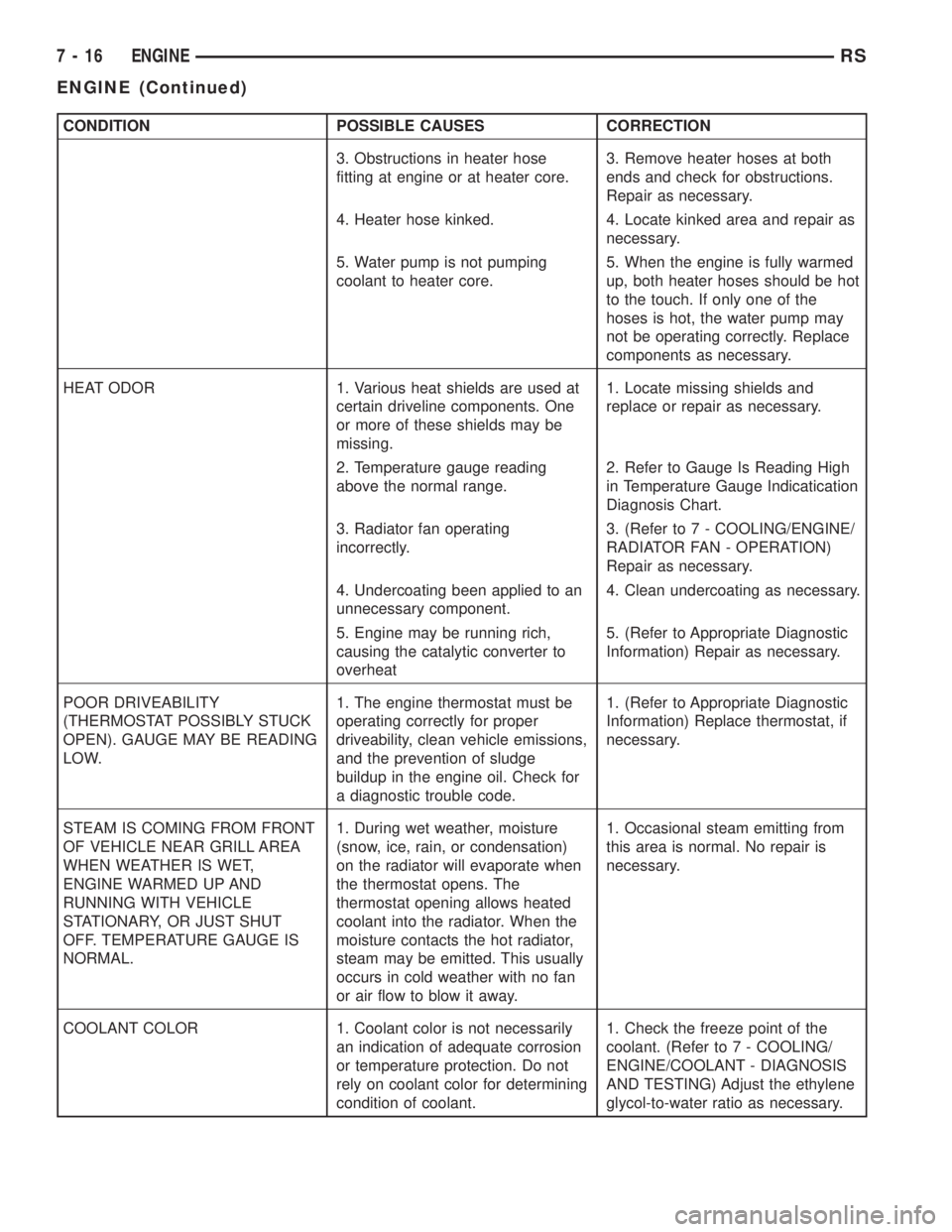
CONDITION POSSIBLE CAUSES CORRECTION
3. Obstructions in heater hose
fitting at engine or at heater core.3. Remove heater hoses at both
ends and check for obstructions.
Repair as necessary.
4. Heater hose kinked. 4. Locate kinked area and repair as
necessary.
5. Water pump is not pumping
coolant to heater core.5. When the engine is fully warmed
up, both heater hoses should be hot
to the touch. If only one of the
hoses is hot, the water pump may
not be operating correctly. Replace
components as necessary.
HEAT ODOR 1. Various heat shields are used at
certain driveline components. One
or more of these shields may be
missing.1. Locate missing shields and
replace or repair as necessary.
2. Temperature gauge reading
above the normal range.2. Refer to Gauge Is Reading High
in Temperature Gauge Indicatication
Diagnosis Chart.
3. Radiator fan operating
incorrectly.3. (Refer to 7 - COOLING/ENGINE/
RADIATOR FAN - OPERATION)
Repair as necessary.
4. Undercoating been applied to an
unnecessary component.4. Clean undercoating as necessary.
5. Engine may be running rich,
causing the catalytic converter to
overheat5. (Refer to Appropriate Diagnostic
Information) Repair as necessary.
POOR DRIVEABILITY
(THERMOSTAT POSSIBLY STUCK
OPEN). GAUGE MAY BE READING
LOW.1. The engine thermostat must be
operating correctly for proper
driveability, clean vehicle emissions,
and the prevention of sludge
buildup in the engine oil. Check for
a diagnostic trouble code.1. (Refer to Appropriate Diagnostic
Information) Replace thermostat, if
necessary.
STEAM IS COMING FROM FRONT
OF VEHICLE NEAR GRILL AREA
WHEN WEATHER IS WET,
ENGINE WARMED UP AND
RUNNING WITH VEHICLE
STATIONARY, OR JUST SHUT
OFF. TEMPERATURE GAUGE IS
NORMAL.1. During wet weather, moisture
(snow, ice, rain, or condensation)
on the radiator will evaporate when
the thermostat opens. The
thermostat opening allows heated
coolant into the radiator. When the
moisture contacts the hot radiator,
steam may be emitted. This usually
occurs in cold weather with no fan
or air flow to blow it away.1. Occasional steam emitting from
this area is normal. No repair is
necessary.
COOLANT COLOR 1. Coolant color is not necessarily
an indication of adequate corrosion
or temperature protection. Do not
rely on coolant color for determining
condition of coolant.1. Check the freeze point of the
coolant. (Refer to 7 - COOLING/
ENGINE/COOLANT - DIAGNOSIS
AND TESTING) Adjust the ethylene
glycol-to-water ratio as necessary.
7 - 16 ENGINERS
ENGINE (Continued)
Page 1837 of 4284
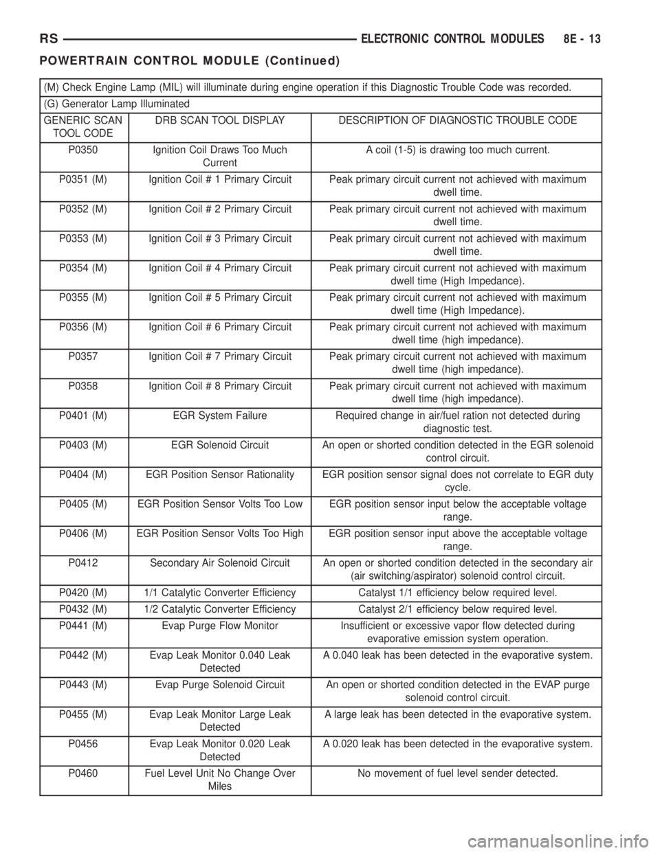
(M) Check Engine Lamp (MIL) will illuminate during engine operation if this Diagnostic Trouble Code was recorded.
(G) Generator Lamp Illuminated
GENERIC SCAN
TOOL CODEDRB SCAN TOOL DISPLAY DESCRIPTION OF DIAGNOSTIC TROUBLE CODE
P0350 Ignition Coil Draws Too Much
CurrentA coil (1-5) is drawing too much current.
P0351 (M) Ignition Coil # 1 Primary Circuit Peak primary circuit current not achieved with maximum
dwell time.
P0352 (M) Ignition Coil # 2 Primary Circuit Peak primary circuit current not achieved with maximum
dwell time.
P0353 (M) Ignition Coil # 3 Primary Circuit Peak primary circuit current not achieved with maximum
dwell time.
P0354 (M) Ignition Coil # 4 Primary Circuit Peak primary circuit current not achieved with maximum
dwell time (High Impedance).
P0355 (M) Ignition Coil # 5 Primary Circuit Peak primary circuit current not achieved with maximum
dwell time (High Impedance).
P0356 (M) Ignition Coil # 6 Primary Circuit Peak primary circuit current not achieved with maximum
dwell time (high impedance).
P0357 Ignition Coil # 7 Primary Circuit Peak primary circuit current not achieved with maximum
dwell time (high impedance).
P0358 Ignition Coil # 8 Primary Circuit Peak primary circuit current not achieved with maximum
dwell time (high impedance).
P0401 (M) EGR System Failure Required change in air/fuel ration not detected during
diagnostic test.
P0403 (M) EGR Solenoid Circuit An open or shorted condition detected in the EGR solenoid
control circuit.
P0404 (M) EGR Position Sensor Rationality EGR position sensor signal does not correlate to EGR duty
cycle.
P0405 (M) EGR Position Sensor Volts Too Low EGR position sensor input below the acceptable voltage
range.
P0406 (M) EGR Position Sensor Volts Too High EGR position sensor input above the acceptable voltage
range.
P0412 Secondary Air Solenoid Circuit An open or shorted condition detected in the secondary air
(air switching/aspirator) solenoid control circuit.
P0420 (M) 1/1 Catalytic Converter Efficiency Catalyst 1/1 efficiency below required level.
P0432 (M) 1/2 Catalytic Converter Efficiency Catalyst 2/1 efficiency below required level.
P0441 (M) Evap Purge Flow Monitor Insufficient or excessive vapor flow detected during
evaporative emission system operation.
P0442 (M) Evap Leak Monitor 0.040 Leak
DetectedA 0.040 leak has been detected in the evaporative system.
P0443 (M) Evap Purge Solenoid Circuit An open or shorted condition detected in the EVAP purge
solenoid control circuit.
P0455 (M) Evap Leak Monitor Large Leak
DetectedA large leak has been detected in the evaporative system.
P0456 Evap Leak Monitor 0.020 Leak
DetectedA 0.020 leak has been detected in the evaporative system.
P0460 Fuel Level Unit No Change Over
MilesNo movement of fuel level sender detected.
RSELECTRONIC CONTROL MODULES8E-13
POWERTRAIN CONTROL MODULE (Continued)
Page 1840 of 4284
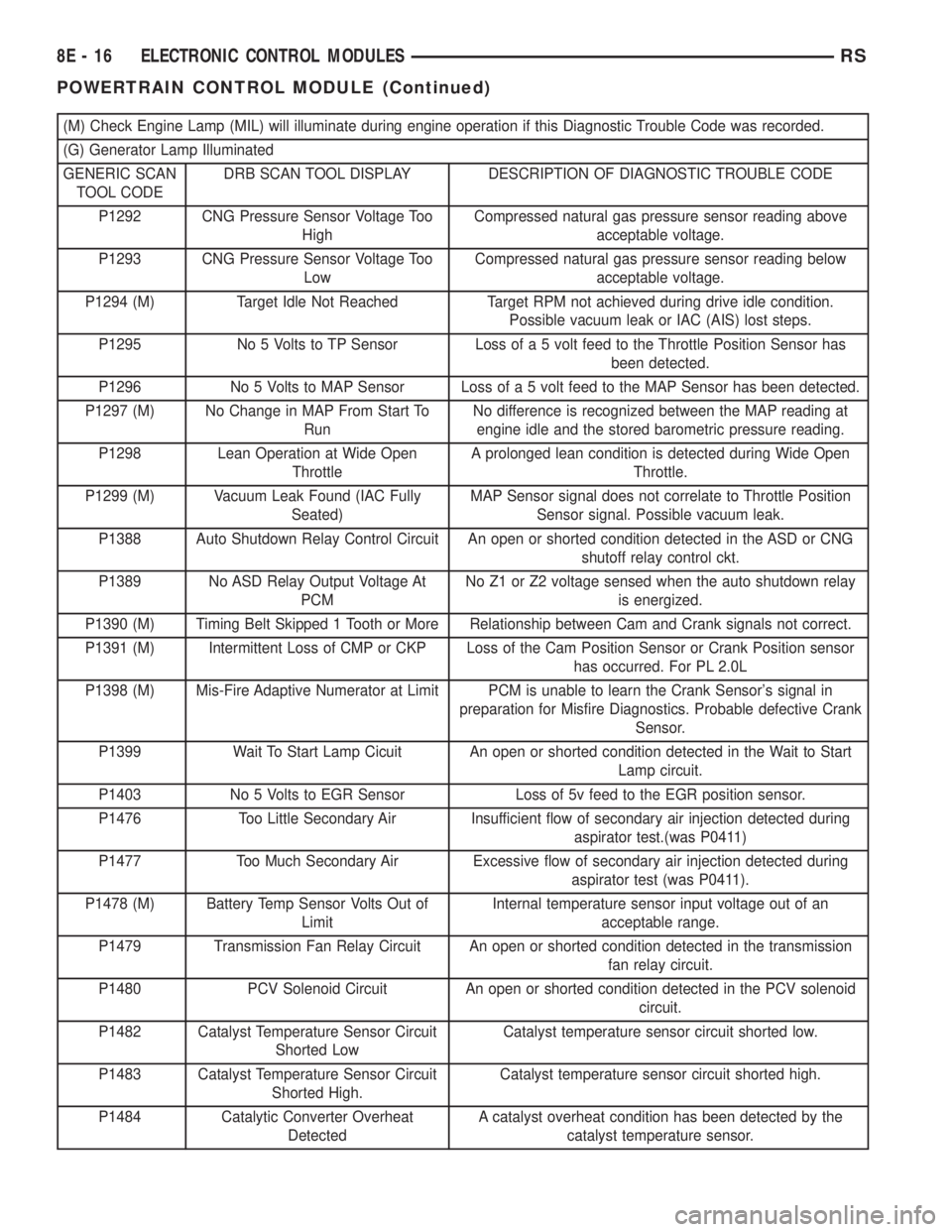
(M) Check Engine Lamp (MIL) will illuminate during engine operation if this Diagnostic Trouble Code was recorded.
(G) Generator Lamp Illuminated
GENERIC SCAN
TOOL CODEDRB SCAN TOOL DISPLAY DESCRIPTION OF DIAGNOSTIC TROUBLE CODE
P1292 CNG Pressure Sensor Voltage Too
HighCompressed natural gas pressure sensor reading above
acceptable voltage.
P1293 CNG Pressure Sensor Voltage Too
LowCompressed natural gas pressure sensor reading below
acceptable voltage.
P1294 (M) Target Idle Not Reached Target RPM not achieved during drive idle condition.
Possible vacuum leak or IAC (AIS) lost steps.
P1295 No 5 Volts to TP Sensor Loss of a 5 volt feed to the Throttle Position Sensor has
been detected.
P1296 No 5 Volts to MAP Sensor Loss of a 5 volt feed to the MAP Sensor has been detected.
P1297 (M) No Change in MAP From Start To
RunNo difference is recognized between the MAP reading at
engine idle and the stored barometric pressure reading.
P1298 Lean Operation at Wide Open
ThrottleA prolonged lean condition is detected during Wide Open
Throttle.
P1299 (M) Vacuum Leak Found (IAC Fully
Seated)MAP Sensor signal does not correlate to Throttle Position
Sensor signal. Possible vacuum leak.
P1388 Auto Shutdown Relay Control Circuit An open or shorted condition detected in the ASD or CNG
shutoff relay control ckt.
P1389 No ASD Relay Output Voltage At
PCMNo Z1 or Z2 voltage sensed when the auto shutdown relay
is energized.
P1390 (M) Timing Belt Skipped 1 Tooth or More Relationship between Cam and Crank signals not correct.
P1391 (M) Intermittent Loss of CMP or CKP Loss of the Cam Position Sensor or Crank Position sensor
has occurred. For PL 2.0L
P1398 (M) Mis-Fire Adaptive Numerator at Limit PCM is unable to learn the Crank Sensor's signal in
preparation for Misfire Diagnostics. Probable defective Crank
Sensor.
P1399 Wait To Start Lamp Cicuit An open or shorted condition detected in the Wait to Start
Lamp circuit.
P1403 No 5 Volts to EGR Sensor Loss of 5v feed to the EGR position sensor.
P1476 Too Little Secondary Air Insufficient flow of secondary air injection detected during
aspirator test.(was P0411)
P1477 Too Much Secondary Air Excessive flow of secondary air injection detected during
aspirator test (was P0411).
P1478 (M) Battery Temp Sensor Volts Out of
LimitInternal temperature sensor input voltage out of an
acceptable range.
P1479 Transmission Fan Relay Circuit An open or shorted condition detected in the transmission
fan relay circuit.
P1480 PCV Solenoid Circuit An open or shorted condition detected in the PCV solenoid
circuit.
P1482 Catalyst Temperature Sensor Circuit
Shorted LowCatalyst temperature sensor circuit shorted low.
P1483 Catalyst Temperature Sensor Circuit
Shorted High.Catalyst temperature sensor circuit shorted high.
P1484 Catalytic Converter Overheat
DetectedA catalyst overheat condition has been detected by the
catalyst temperature sensor.
8E - 16 ELECTRONIC CONTROL MODULESRS
POWERTRAIN CONTROL MODULE (Continued)
Page 2637 of 4284
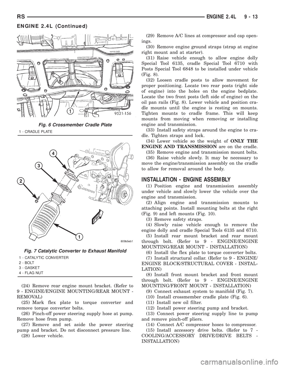
(24) Remove rear engine mount bracket. (Refer to
9 - ENGINE/ENGINE MOUNTING/REAR MOUNT -
REMOVAL)
(25) Mark flex plate to torque converter and
remove torque converter bolts.
(26) Pinch-off power steering supply hose at pump.
Remove hose from pump.
(27) Remove and set aside the power steering
pump and bracket. Do not disconnect pressure line.
(28) Lower vehicle.(29) Remove A/C lines at compressor and cap open-
ings.
(30) Remove engine ground straps (strap at engine
right mount and at starter).
(31) Raise vehicle enough to allow engine dolly
Special Tool 6135, cradle Special Tool 6710 with
Posts Special Tool 6848 to be installed under vehicle
(Fig. 8).
(32) Loosen cradle posts to allow movement for
proper positioning. Locate two rear posts (right side
of engine) into the holes on the engine bedplate.
Locate the two front posts (left side of engine) on the
oil pan rails (Fig. 8). Lower vehicle and position cra-
dle mounts until the engine is resting on mounts.
Tighten mounts to cradle frame. This will keep
mounts from moving when removing or installing
engine and transmission.
(33) Install safety straps around the engine to cra-
dle. Tighten straps and lock.
(34) Lower vehicle so the weight ofONLY THE
ENGINE AND TRANSMISSIONare on the cradle.
(35) Remove engine and transmission mount bolts.
(36) Raise vehicle slowly. It may be necessary to
move the engine/transmission assembly on the cradle
to allow for removal around the body.
INSTALLATION - ENGINE ASSEMBLY
(1) Position engine and transmission assembly
under vehicle and slowly lower the vehicle over the
engine and transmission.
(2) Align engine and transmission mounts to
attaching points. Install mounting bolts at the right
(Fig. 9) and left mounts (Fig. 10).
(3) Remove safety straps.
(4) Slowly raise vehicle enough to remove the
engine dolly and cradle Special Tools 6135 and 6710.
(5) Install rear mount bracket and rear mount
through bolt. (Refer to 9 - ENGINE/ENGINE
MOUNTING/REAR MOUNT - INSTALLATION)
(6) Install the flex plate to torque converter bolts.
(7) Install structural collar. (Refer to 9 - ENGINE/
ENGINE BLOCK/STRUCTURAL COVER - INSTAL-
LATION)
(8) Install front mount bracket and front mount
through bolt. (Refer to 9 - ENGINE/ENGINE
MOUNTING/FRONT MOUNT - INSTALLATION)
(9) Connect exhaust system to manifold (Fig. 7).
(10) Install crossmember cradle plate (Fig. 6).
(11) Install new oil filter.
(12) Install power steering pump and bracket.
(13) Connect power steering supply line to pump
and remove pinch-off pliers.
(14) Connect A/C compressor hoses to compressor.
(15) Install accessory drive belts. (Refer to 7 -
COOLING/ACCESSORY DRIVE/DRIVE BELTS -
INSTALLATION)
Fig. 6 Crossmember Cradle Plate
1 - CRADLE PLATE
Fig. 7 Catalytic Converter to Exhaust Manifold
1 - CATALYTIC CONVERTER
2 - BOLT
3 - GASKET
4 - FLAG NUT
RSENGINE 2.4L9-13
ENGINE 2.4L (Continued)
Page 2707 of 4284
(36) Remove front engine mount and bracket as an
assembly.
(37) Remove the engine rear mount bracket.
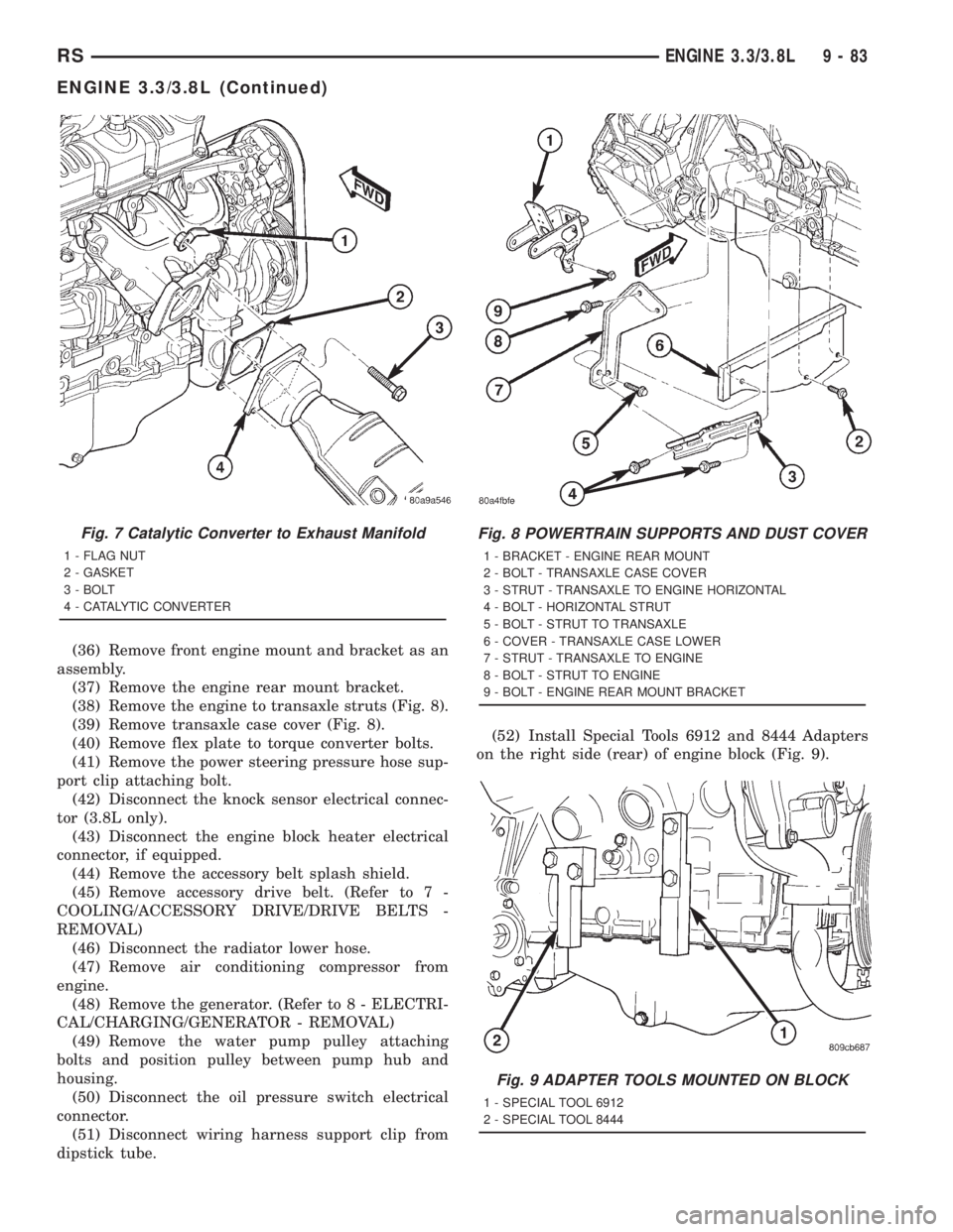
(38) Remove the engine to transaxle struts (Fig. 8).
(39) Remove transaxle case cover (Fig. 8).
(40) Remove flex plate to torque converter bolts.
(41) Remove the power steering pressure hose sup-
port clip attaching bolt.
(42) Disconnect the knock sensor electrical connec-
tor (3.8L only).
(43) Disconnect the engine block heater electrical
connector, if equipped.
(44) Remove the accessory belt splash shield.
(45) Remove accessory drive belt. (Refer to 7 -
COOLING/ACCESSORY DRIVE/DRIVE BELTS -
REMOVAL)
(46) Disconnect the radiator lower hose.
(47) Remove air conditioning compressor from
engine.
(48) Remove the generator. (Refer to 8 - ELECTRI-
CAL/CHARGING/GENERATOR - REMOVAL)
(49) Remove the water pump pulley attaching
bolts and position pulley between pump hub and
housing.
(50) Disconnect the oil pressure switch electrical
connector.
(51) Disconnect wiring harness support clip from
dipstick tube.(52) Install Special Tools 6912 and 8444 Adapters
on the right side (rear) of engine block (Fig. 9).
Fig. 7 Catalytic Converter to Exhaust Manifold
1 - FLAG NUT
2 - GASKET
3 - BOLT
4 - CATALYTIC CONVERTER
Fig. 8 POWERTRAIN SUPPORTS AND DUST COVER
1 - BRACKET - ENGINE REAR MOUNT
2 - BOLT - TRANSAXLE CASE COVER
3 - STRUT - TRANSAXLE TO ENGINE HORIZONTAL
4 - BOLT - HORIZONTAL STRUT
5 - BOLT - STRUT TO TRANSAXLE
6 - COVER - TRANSAXLE CASE LOWER
7 - STRUT - TRANSAXLE TO ENGINE
8 - BOLT - STRUT TO ENGINE
9 - BOLT - ENGINE REAR MOUNT BRACKET
Fig. 9 ADAPTER TOOLS MOUNTED ON BLOCK
1 - SPECIAL TOOL 6912
2 - SPECIAL TOOL 8444
RSENGINE 3.3/3.8L9-83
ENGINE 3.3/3.8L (Continued)
Page 2775 of 4284
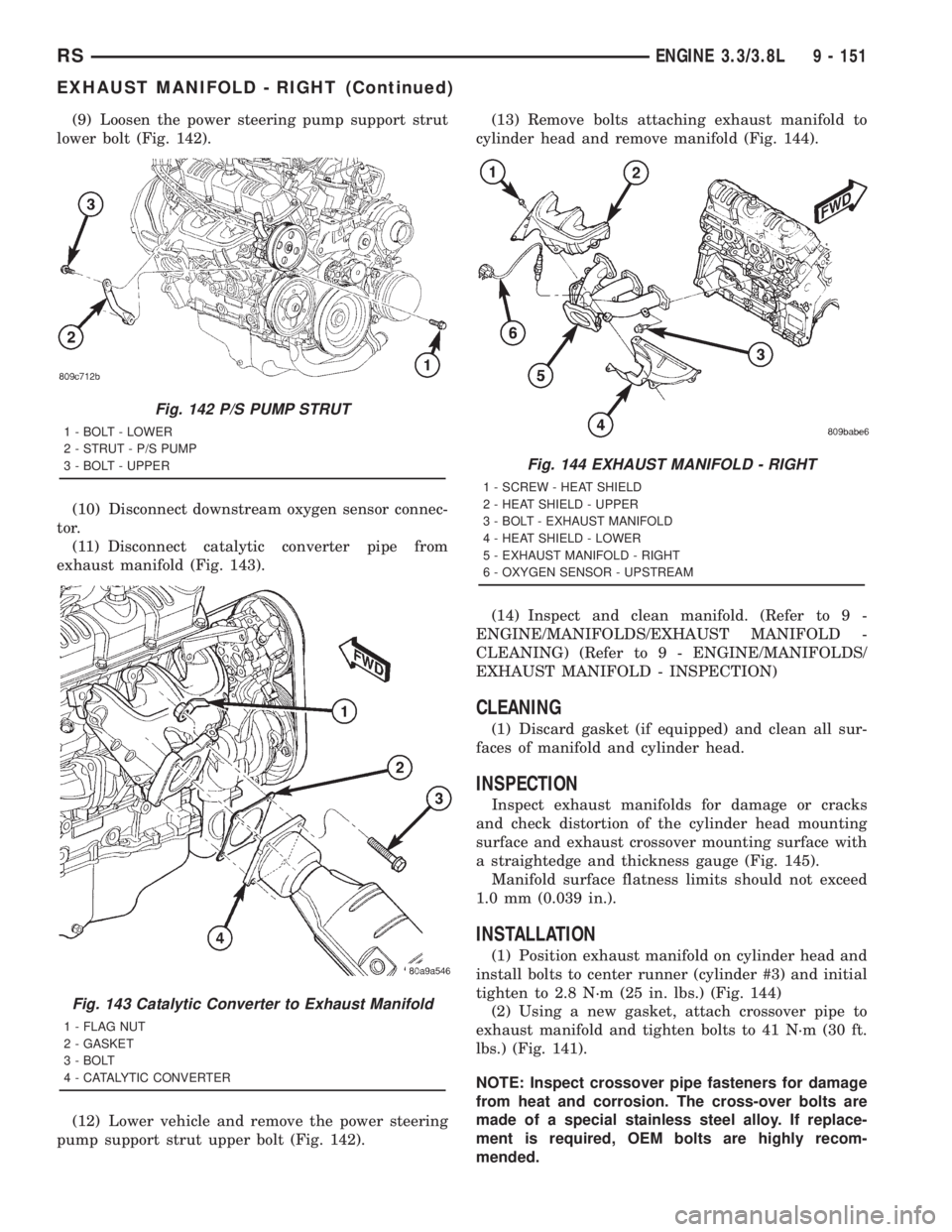
(9) Loosen the power steering pump support strut
lower bolt (Fig. 142).
(10) Disconnect downstream oxygen sensor connec-
tor.
(11) Disconnect catalytic converter pipe from
exhaust manifold (Fig. 143).
(12) Lower vehicle and remove the power steering
pump support strut upper bolt (Fig. 142).(13) Remove bolts attaching exhaust manifold to
cylinder head and remove manifold (Fig. 144).
(14) Inspect and clean manifold. (Refer to 9 -
ENGINE/MANIFOLDS/EXHAUST MANIFOLD -
CLEANING) (Refer to 9 - ENGINE/MANIFOLDS/
EXHAUST MANIFOLD - INSPECTION)
CLEANING
(1) Discard gasket (if equipped) and clean all sur-
faces of manifold and cylinder head.
INSPECTION
Inspect exhaust manifolds for damage or cracks
and check distortion of the cylinder head mounting
surface and exhaust crossover mounting surface with
a straightedge and thickness gauge (Fig. 145).
Manifold surface flatness limits should not exceed
1.0 mm (0.039 in.).
INSTALLATION
(1) Position exhaust manifold on cylinder head and
install bolts to center runner (cylinder #3) and initial
tighten to 2.8 N´m (25 in. lbs.) (Fig. 144)
(2) Using a new gasket, attach crossover pipe to
exhaust manifold and tighten bolts to 41 N´m (30 ft.
lbs.) (Fig. 141).
NOTE: Inspect crossover pipe fasteners for damage
from heat and corrosion. The cross-over bolts are
made of a special stainless steel alloy. If replace-
ment is required, OEM bolts are highly recom-
mended.
Fig. 142 P/S PUMP STRUT
1 - BOLT - LOWER
2 - STRUT - P/S PUMP
3 - BOLT - UPPER
Fig. 143 Catalytic Converter to Exhaust Manifold
1 - FLAG NUT
2 - GASKET
3 - BOLT
4 - CATALYTIC CONVERTER
Fig. 144 EXHAUST MANIFOLD - RIGHT
1 - SCREW - HEAT SHIELD
2 - HEAT SHIELD - UPPER
3 - BOLT - EXHAUST MANIFOLD
4 - HEAT SHIELD - LOWER
5 - EXHAUST MANIFOLD - RIGHT
6 - OXYGEN SENSOR - UPSTREAM
RSENGINE 3.3/3.8L9 - 151
EXHAUST MANIFOLD - RIGHT (Continued)
Page 2776 of 4284
(3) Install the remaining manifold attaching bolts.
Tighten all bolts to 23 N´m (200 in. lbs.).
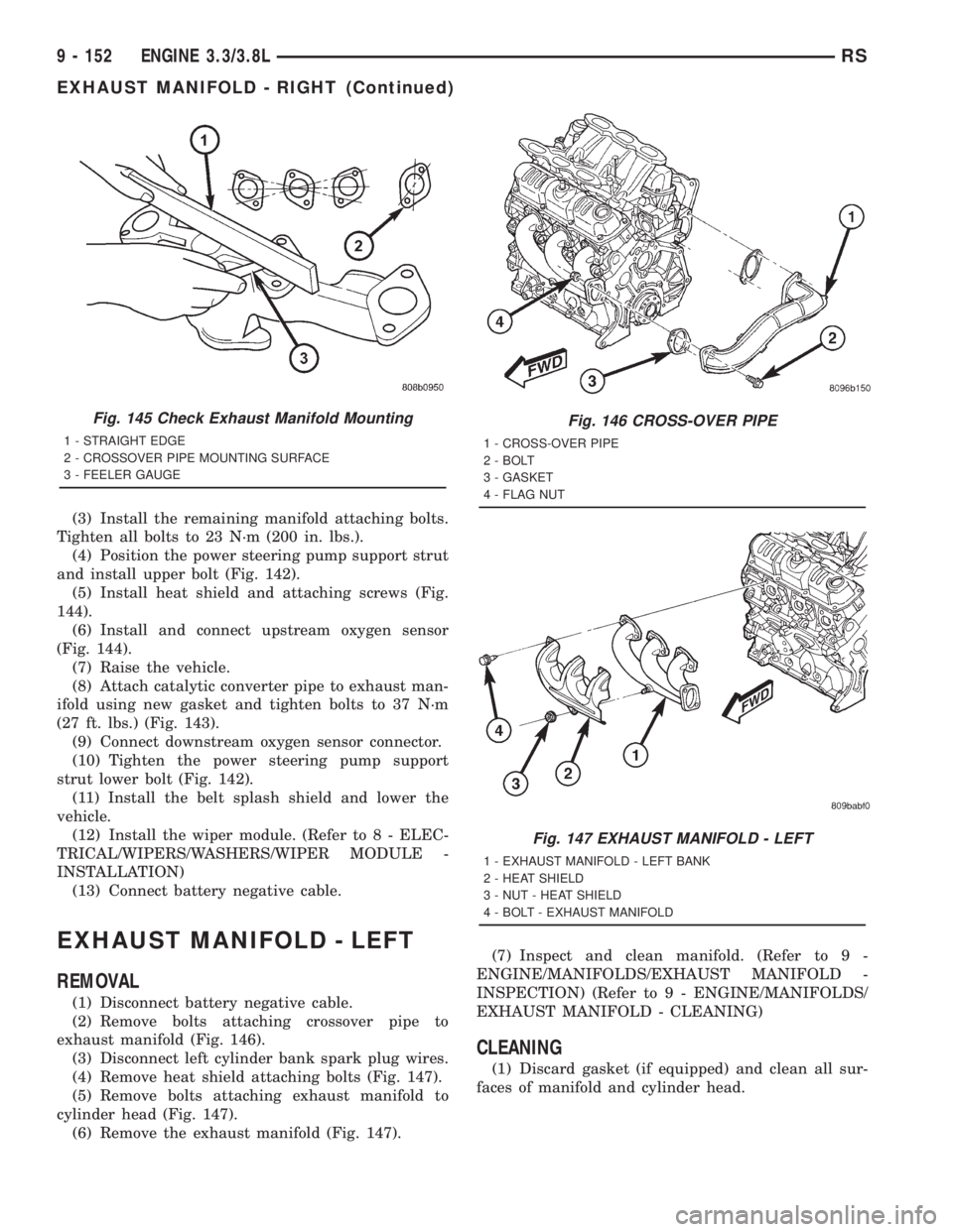
(4) Position the power steering pump support strut
and install upper bolt (Fig. 142).
(5) Install heat shield and attaching screws (Fig.
144).
(6) Install and connect upstream oxygen sensor
(Fig. 144).
(7) Raise the vehicle.
(8) Attach catalytic converter pipe to exhaust man-
ifold using new gasket and tighten bolts to 37 N´m
(27 ft. lbs.) (Fig. 143).
(9) Connect downstream oxygen sensor connector.
(10) Tighten the power steering pump support
strut lower bolt (Fig. 142).
(11) Install the belt splash shield and lower the
vehicle.
(12) Install the wiper module. (Refer to 8 - ELEC-
TRICAL/WIPERS/WASHERS/WIPER MODULE -
INSTALLATION)
(13) Connect battery negative cable.
EXHAUST MANIFOLD - LEFT
REMOVAL
(1) Disconnect battery negative cable.
(2) Remove bolts attaching crossover pipe to
exhaust manifold (Fig. 146).
(3) Disconnect left cylinder bank spark plug wires.
(4) Remove heat shield attaching bolts (Fig. 147).
(5) Remove bolts attaching exhaust manifold to
cylinder head (Fig. 147).
(6) Remove the exhaust manifold (Fig. 147).(7) Inspect and clean manifold. (Refer to 9 -
ENGINE/MANIFOLDS/EXHAUST MANIFOLD -
INSPECTION) (Refer to 9 - ENGINE/MANIFOLDS/
EXHAUST MANIFOLD - CLEANING)
CLEANING
(1) Discard gasket (if equipped) and clean all sur-
faces of manifold and cylinder head.
Fig. 145 Check Exhaust Manifold Mounting
1 - STRAIGHT EDGE
2 - CROSSOVER PIPE MOUNTING SURFACE
3 - FEELER GAUGE
Fig. 146 CROSS-OVER PIPE
1 - CROSS-OVER PIPE
2 - BOLT
3 - GASKET
4 - FLAG NUT
Fig. 147 EXHAUST MANIFOLD - LEFT
1 - EXHAUST MANIFOLD - LEFT BANK
2 - HEAT SHIELD
3 - NUT - HEAT SHIELD
4 - BOLT - EXHAUST MANIFOLD
9 - 152 ENGINE 3.3/3.8LRS
EXHAUST MANIFOLD - RIGHT (Continued)